
Document Title: Function Group: Information Type: Date:
Description 600 Service Information 2015/10/22
Profile:
GRD, G730B [GB]
Description
Overview – G710B to G746B
The front axle of a motor grader performs several functions: steering, axle pivot, and wheel lean. It must also be capable of carrying heavy front mounted attachments.
Tandem drive and AWD (All Wheel Drive) grader front axles share a group of common parts. What differentiates the two axles is the “wheel group” that attaches to the knuckle. A tandem drive grader uses a spindle to mount a wheel hub. An AWD grader uses a cradle to mount a hydraulic motor.
Steering
Two hydraulic cylinders pivot the spindles or cradles on king pins in the knuckle. Bushings support the king pins in the knuckle frame. The drag link makes both sides turn together. On tandem drive graders, the king pins are retained by square head setscrews. On AWD graders, however, socket head setscrews are used to provide clearance for hoses. Thrust loads are transmitted between the knuckle and spindle or cradle by a special thrust washer.
Pivoting axle
The pivot of the front axle allows the front wheels to travel over uneven ground with minimal main frame movement. The axle frame mounts onto a pivot pin welded to the main frame. Angular contact bushings, which are pre-loaded and shim adjustable, support the axle frame on the pivot pin. With the front axle raised off the ground, a person weighing 68 – 82 kg (150 – 180 lb) should be able to move the axle on the pivot pin. Stop blocks restrict axle pivot to 16º on each side of the grader's center line.
Wheel lean
Leaning the wheels reduces the turning radius, braces against moldboard imposed side loads, and gives better stability while grading on slopes. Setscrews retain the pivot pins in the knuckles. The pivot pins are supported in the axle frame by spherical bushings. End float is 0,000 – 0,102 mm (0.000 – 0.004 in.) and is shim adjustable. One or two hydraulic cylinders pivot the knuckles and pins to a maximum of 18º each side of center. A lock valve prevents cylinder drift under load. The tie bar keeps both wheels parallel so that they lean together. The pivot block, like a universal joint, allows movement in two directions during wheel lean and steering. Slightly pre-loaded bushings and thrust washers are used in the pivot block.
Wheel hub – Tandem drive wheel group
Two tapered roller bearings support the wheel hub. The spindle locknut tightness determines preload. A V-ring seal prevents bearing cavity pressurization and dirt ingress.
Wheel hub – AWD Wheel group
A hydraulic motor is mounted directly onto the AWD hub. The hub mounts into the knuckle the same as the tandem drive axle. A hose guard is mounted to the back of the hub to protect the hydraulic hoses.
Toe-in
The term “toe-in” means that the distance between the front (toe) of the tires is less than the distance between the rear of the tires. On tandem drive models, toe-in is 3 – 6,5 mm (1/8 – 1/4 in.). On AWD models there is no toe-in as front wheels are also driving wheels. Toe-in is altered by adjusting the drag link length.
Thanks very much for your reading, Want to get more information, Please click here, Then get the complete manual

NOTE: please download the PDF document first, and then click on it.

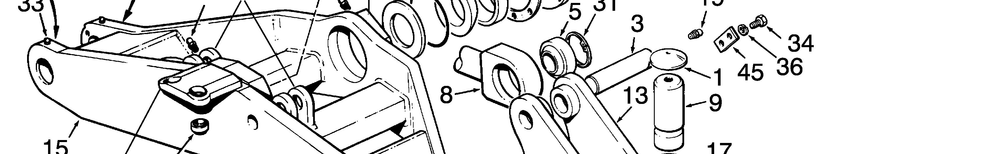


Back-up washer
Bearing pin
Bearing
Bearing
Bearing cap
Pivot pin
Tie bar
King pin
Shim
Spacer
Bearing
Knuckle - R.H and L.H.
Gasket - hub cap
Front axle
Hub cap
Bushing
Roll pin
Grease fitting
Thrust washer
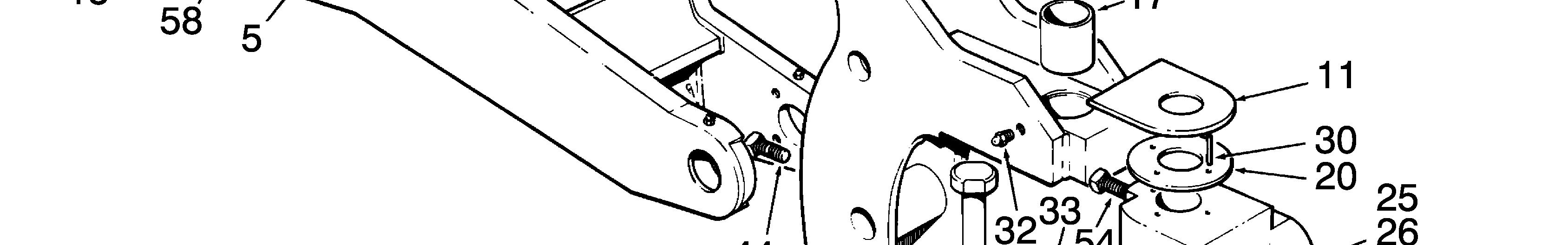
Cap
Shim - 0.010 in.
Shim - 0.005 in.
Pin
Hub and spindle - L.H.
Hub and spindle - R.H.
Shim - 0.007 in.
O-ring
Cotter pin
Roll pin
Snap ring - internal
Grease fitting
Grease fitting
Bolt
Bolt
Lock washer
Bolt
Lock washer
Locknut
Tabwasher
Washer - wheel bearing
Flat washer
Slotted nut
Setscrew
Lock plate
V-ring seal
Back-up ring
Cup - inner bearing
Cone - inner bearing
Cup - outer bearing
Cone - outer bearing
Bolt
Lock washer
Setscrew
Grease fitting
Front bearing mount
Lug - wheel lean cylinder
Anchor lug - steering cylinder
Pin and lug assembly
Pin
Lug
Hub - wheel
AWD models
AWD hub - RH and LH
AWD wheel motor
Hose guard
2
Drag link – G710B to G746B
Cap
Bearing pin
Bearing pin
Bearing
Lock plate
Bushing
Thrust washer
Anchor pin
Grease fitting
Jam nut - L.H.
Yoke - L.H.
Yoke - R.H.
Pivot block
Pivot pin
Drag link
Bushing
Cotter pin
Roll pin
Lock washer
Snap ring - internal
Snap ring - external
Grease fitting
Bolt
Document Title: Function Group: Information Type: Date: Steering axle – Disassembly 622 Service Information 2015/10/22
Profile: GRD, G730B [GB]
Steering axle – Disassembly
The following pages describe how to overhaul the front axle for Models G710B to G746B. Overhaul instructions for the heavy-duty front axle (installed on the Model G780B) are described later in this section. Before starting the overhaul procedure, make sure work area is clean and safe. Make sure proper tools, including a safe lifting device, are available and in good working order. Read all warnings and act accordingly.
NOTE!
Place the grader in the Service Position before starting this overhaul procedure. Refer to 191 Service positions
Document Title: Function Group: Information Type: Date: Preparation and Wheel Removal 622 Service Information 2015/10/22
Profile: GRD, G730B [GB]
Preparation and Wheel Removal
Op nbr 622-051
1. Start the engine when it is safe to do so. Position the moldboard centrally on the circle and 90º to the frame. Lower the moldboard onto wooden blocks. Shut down the engine.

WARNING
Never work under/on machines without using recommended support equipment.
2. Loosen the wheel rim bolts with the tires on the ground. Start the engine and operate the blade lift cylinders to raise the front end of the grader. Place a safe stand under the nose of the grader. Operate the blade lift cylinders and lower the front end of the grader onto the stand. Shut down the engine. Remove and retain the ignition key.
3. Remove the wheel rim bolts and lock washers and roll the rims and tires away from the front axle.


Document Title: Function Group: Information Type: Date: Wheel Hub - Removal 622 Service Information 2015/10/22
Profile: GRD, G730B [GB]
Wheel Hub - Removal
Op nbr 622-052
18516 Socket wrench
1. Attach a safe lifting device to the wheel hub. Remove the hub cap. Remove and discard the hub cap gasket.
2. Bend back the tabs of the tabwasher. Using the special tool P/N 18516, remove the outer locknut, tabwasher and inner locknut. Discard the tabwasher. Remove the wheel bearing washer.
3. Pull the wheel hub out slightly on the spindle and remove the outer bearing cone. Remove the wheel hub from the spindle.

4. Remove the inner bearing cone. Remove and discard the back-up ring and V-ring seal.
5. Inspect the bearing cups for signs of damage or wear. If necessary, use a hammer and soft metal drift to remove them. If replacing the bearing cups, place them in a freezer to shrink them for easier installation.
Document Title: Function Group: Information Type: Date: Steering CylinderRemoval 622 Service Information 2015/10/22
Profile: GRD, G730B [GB]
Steering Cylinder - Removal
Op nbr 622-053
WARNING
Compressed air. Never direct to bare skin. Use protective equipment.
NOTE!
Residual pressure may remain in hydraulic circuits containing lock valves.
1. Identify the hydraulic hoses to prevent confusion during assembly. Disconnect the steering cylinder hoses. Plug the open ports and fittings to prevent contamination.
2. Remove the bolts and lock washers retaining the piston rod end cap. Remove the end cap. Remove and discard the external snap ring.
3. Use a suitable puller to remove the piston rod end from the yoke pivot stud.

4. Remove the bolts, lock washers and lock plate from the cylinder barrel end.
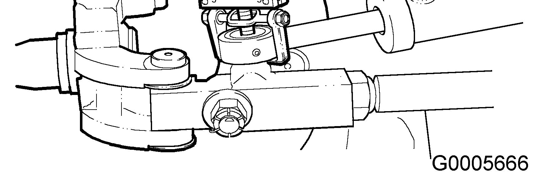
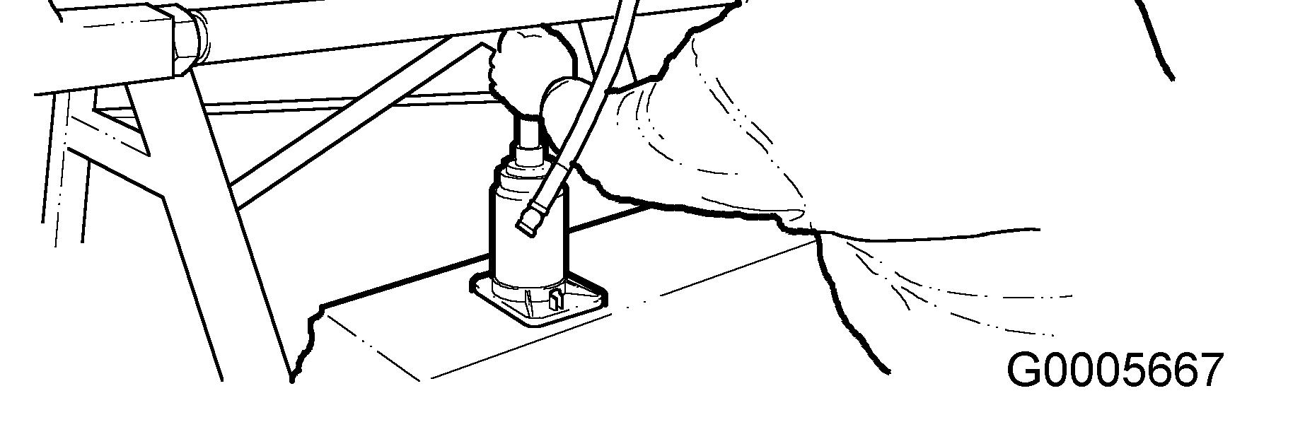
5. Use a bottle jack under the cylinder barrel anchor pin and remove the pin. Remove the steering cylinder from the front axle. Remove the bearing from the anchor lug.
NOTE!
The bearing can only be removed in one direction.

6. Place the steering cylinder on a clean workbench. Remove and discard the internal snap ring. Use a hammer and appropriate drift to remove the bearing.
7. Examine the bearings for signs of damage or wear and replace if necessary.
8. Repeat the removal procedure for the other steering cylinder.
Document Title: Function Group: Information Type: Date: Drag link, removing 622 Service Information 2015/10/22
Profile: GRD, G730B [GB]
Drag link, removing
Op nbr 622-054
1. Use a safe lifting device to support the drag link. Remove and discard the cotter pin securing the slotted nut that retains the pivot pin. Remove the slotted nut, flat washer and pivot pin.


2. Repeat the disassembly procedure for the other pivot pin. Remove the drag link from the front axle. Remove the thrust washers.


Document Title: Function Group: Information Type: Date: Pivot block, removing and disassembling 622 Service Information 2015/10/22
Profile: GRD, G730B [GB]
Pivot block, removing and disassembling
Op nbr 622-055
1. Remove and discard the cotter pin securing the slotted nut that retains the pivot block pin. Remove the slotted nut, flat washer and pivot block pin. Slide the pivot block out of the spindle clevis and remove the thrust washers.
2. Place the pivot block in a vise. Use a hammer and soft metal drift to remove the bushings. Discard the bushings.
3. Repeat the disassembly procedure for the other pivot block.
Document Title: Function Group: Information Type: Date: Spindle - Removal and Disassembly 622 Service Information 2015/10/22
Profile: GRD, G730B [GB]
Spindle - Removal and Disassembly
Op nbr 622-056
1. Remove the setscrews securing the upper and lower king pins.


2. Cut a slot in the upper and lower expansion plugs. Remove and discard the plugs.
3. Use a safe lifting device to support the spindle. Use a slide hammer to force the upper and lower king pins out of the spindle.
4. Carefully slide the spindle out of the knuckle. Remove the thrust washer and upper and lower spacers. Use a hammer and soft metal drift to remove the king pin bushings. Discard the bushings.