G700B
This Operator’s Manual is intended as a guide for the correct use and maintenance of the machine. Therefore, study it carefully before starting and operating the machine, or before carrying out any preventive maintenance. Keep the manual in the manual box in the cab so that it is always at hand. Replace it immediately if it is lost.
NOTE: The manual describes the applications for which the machine is primarily intended, and is written to apply for all markets. We therefore ask you to disregard the sections that are not applicable to your machine or to the work for which you use your machine.
Many hours are spent on design and production to make a machine that is as efficient and safe as possible. The accidents that occur in spite of this are mostly caused by the human factor. A safety-conscious person and a well maintained machine make a safe, efficient and profitable combination. Therefore, read the safety instructions and follow them.
Every new Volvo Motor Grader is shipped with a CIMA Grader Safety Manual published by the Construction Industry Manufacturers’ Association. Read it carefully before operating or servicing your grader.
We continually strive to improve our products and to make them more efficient through changes to their design. We retain the right to make these changes without committing ourselves to introducing these improvements on products that have already been delivered.
We also retain the right to change data and equipment, as well as instructions for service and maintenance, without prior notice.
SAFETY REGULATIONS
It is the operator’s obligation to know and follow the applicable national and local safety regulations. The safety instructions in this manual only apply to cases when there are no national or local regulations.
WARNING!
Contents
OPERATOR’S MANUAL
Presentation

The symbol above appears at various points in the manual together with warning text. It means – Warning, be alert! Your safety is involved. It is the obligation of the operator to make sure that all warning decals are in place on the machine and that they are readable. Accidents may otherwise occur.
Know the capacity and limits of your machine!
This manual applies to Serial Number 35000 and up.
Instrument panels
Controls
Operating instructions
Operating techniques
Safety when servicing
Service and maintenance
Specifications
Alphabetical index
State the PIN number of the machine (serial number) below. Always state this information when contacting the manufacturer and when ordering spare parts. It is also a good idea to note the serial number of the components.
ManufacturerVolvo Motor Graders Limited 160 Maitland Road, Goderich, Ontario, Canada N7A 3Y6
The PIN number of the machine (serial number)
Engine
Transmission
Final drive
7
MBCS status lamp (amber)
The lamp indicates the MBCS (Moveable Blade Control System) lock is disengaged. Refer to Moveable Blade Control System page 107.
8
WARNING!
Operate the system only long enough to make a steering correction –maximum two minutes.
Parking brake applied (red)
This lamp indicates the parking brake is applied. If the brake is applied when the transmission is in gear, the lamp is accompanied by the red central warning lamp, buzzer, and display message.
9
Engine air filter restriction (amber)
This lamp indicates restricted air flow through the engine air filter and is accompanied by the amber central warning lamp. If this lamp lights up, service or clean the engine air filter. Refer to Service and maintenance, Engine air filter elements page 170.
10
Filter bypass warning (amber)
(optional)
This lamp indicates either the transmission or hydraulic filter is clogged. It is accompanied by a message in the display panel identifying which filter is bypassing and the amber central warning lamp.
11
Primary steering system (red)
(Secondary steering option only)
This lamp indicates low steering system hydraulic pressure. It is accompanied by the red central warning, buzzer, and display message.
The Secondary steering option is an auxiliary hydraulic system that allows the operator to make steering corrections more easily in the event of loss of hydraulic flow to the steering unit. The ignition key must be in the “I” (running) position for this system to function. The system will also turn on when the test switch is activated, see below.
Secondary steering system check
Refer to Secondary steering system test switch page 42.
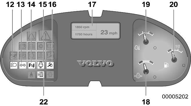
12
High beam (blue)
The blue control lamp is on when the high beam lights are on. Refer to the Directional indicator/High beam/Horn button page 43.
13
Directional indicators (green)
This lamp flashes when the directional indicator lever is moved for turning left or right and when the 4-way hazard flasher switch is activated.
14
Differential lock status (amber)
This lamp energizes when the differential lock is in the LOCK position.
15
Engine preheat (amber)
This lamp indicates the engine preheating element is on. Refer to Side console instrument panel, Engine preheat switch page 49.
After 10 to 50 seconds (the time depends on the coolant temperature) the preheating element will be disconnected and the lamp extinguished.
For cold starting instructions, refer to Starting the engine page 85.
16
Secondary steering system status (amber)
(Secondary steering option only)
This lamp will energize simultaneously with the Primary steering system lamp. It indicates the secondary steering system has been activated.
17
Display unit
For display information, refer to the Pedestal head instruments, Keypad, display unit page 30.
18
Engine oil pressure gauge
The pointer displays the current engine oil pressure. If the pointer enters the red sector, the lamp beside the gauge will illuminate along with the red central warning, buzzer, and display message.
19
Engine coolant temperature gauge
The pointer displays the current engine coolant temperature. If the pointer enters the red sector, the lamp beside the gauge will illuminate along with the red central warning, buzzer, and display message.
20
Fuel gauge
The gauge shows the current level in the fuel tank. Check your fuel supply when the grader is on level ground. If the pointer moves into the red area, the warning lamp will illuminate indicating the machine should be refuelled. In this situation, there is approximately 17% of fuel capacity left. Refuel the machine to avoid air entering the system.
If the tank has been run empty, see Bleeding the fuel system page 168 under Service and maintenance.
Fill the tank at the end of each shift. This reduces the chance of condensation forming in the fuel tank.
For the capacity of the fuel tank, see Specifications, Capacities page 219.
21
(not used)
22
Hydraulic oil level (red)
(optional)
This lamp illuminates when the hydraulic oil level is too low in the reservoir. It is accompanied by the red central warning lamp, buzzer, and display message.
23 (not used)
Pedestal instrument panel
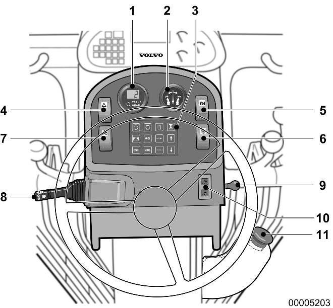
1Transmission gear display
2Articulation indicator gauge
3Keypad, display unit
4Four-way hazard flasher
5Differential lock switch
6MBCS lock pin
CodeMeaning
.8.8LCD (Liquid Crystal Display) test
7.8ECU (Electronic Control Unit) identification
8.4ECU identification (All Wheel Drive)
1Last gear memorized* (example)
-1Opposite gear* (example)
* Alternating display while in neutral
1
7Secondary steering system test
8Directional indicator/ High beam/Horn
9Float valves power switch
10Float valves system indicator lights
11Parking brake switch
Transmission gear display
The transmission gear display is located in the top left-hand side of the pedestal. It displays the transmission gear selected.
With the shift lever in the FORWARD position, the display shows the number of the forward gear, for example ‘3’.
With the shift lever in the REVERSE position, the display shows a negative number, for example ‘-2’.
Refer to Shifting gears page 87.
The gear display can also provide other information: It indicates a Start code sequence on start-up.
It shows an error code if there is a fault in the transmission or All Wheel Drive electrical system.
Start code sequence
When you start the engine, the transmission gear display will show a series of codes called the Start code sequence
Error codes
The transmission ECU (electronic control unit) continuously monitors the transmission and the AWD (All Wheel Drive) electrical system. In the event of a malfunction in either of these systems, an error code is shown in the gear display. Record any error codes and have the electrical system repaired by a qualified service technician. For further information on Error Codes, see the Service manual.
Transmission error codes
If a malfunction occurs in the transmission electrical system, the gear display shows the letter ‘E’ followed by a two-digit numeric code. Multiple error codes are possible. The ECU disables the transmission shifter and places the transmission in NEUTRAL. The display alternates between ‘E’ and the code until the operator returns the shift lever to the NEUTRAL position.
“1.0” series error codes indicate insufficient power available for transmission solenoids. The transmission will not operate until this problem has been resolved.
“2.0” or “3.0” series error codes indicate either an open or short circuit in a transmission solenoid. An alternate gear can be selected by returning the transmission to NEUTRAL. This will allow the grader to be moved.
“2.8” or “3.8” series error codes indicate either an open or short circuit in the parking brake solenoid. The grader will not operate until this problem has been resolved.
“4.2” error code indicates the fault may be corrected by placing the shifter in NEUTRAL then back into gear.
“4.4” error code indicates a multiple shift command error. More than one proximity switch has been energized simultaneously. The circuit board must be replaced to correct this problem.
“4.6” error code indicates there is a problem with the shift lever. The shift lever is out of neutral with no signal to the forward or reverse solenoids.
“P” series error codes indicate a malfunction in the parking brake electrical system.
AWD (All Wheel Drive) error codes
The transmission ECU continuously monitors the AWD electrical system. It is able to detect abnormal conditions and alert the operator of a problem by displaying a code that will aid in correcting the problem.
If a malfunction occurs:
1The transmission gear display shows the letter “E” followed by a 2-digit alphanumeric code. Multiple error codes are possible.
2The display alternates between “E” and the error code until the malfunction is corrected. The transmission is not disabled. Record the error codes and have the AWD electrical system repaired by a qualified service technician. Some error codes will disable the AWD system.
NOTE! “L1”, “L2” and “L4” Series error codes indicate a serious problem with hydraulic oil temperature, level or pressure. Shut the grader down immediately and correct the problem.
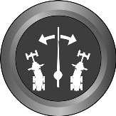
2
Articulation indicator gauge
The indicator needle displays the degree the grader frame is articulated. The frame is straight with the needle in the center position.
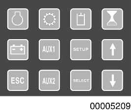
1Engine 7Arrow down
2Transmission8Setup
3Hydraulics9Select
4Hourmeter 10Auxiliary 2
5Electrical system 11Auxiliary 1
6Arrow up 12Esc
3
Keypad, display unit
The keypad allows access to information in different areas of the grader. The information is organized into systems (function groups).
Engine
Engine speed, Coolant temperature, Oil pressure, Air inlet temperature, Boost temperature, Boost pressure, Fuel temperature, Fuel pressure (G740B, G746B and G780B only), Coolant level.
Transmission
Transmission oil pressure, Filter bypass (optional), VHP status
Hydraulics
Brake pressure, Hydraulic filter bypass (optional), Hydraulic oil temperature (optional), Hydraulic oil level (optional).
Electrical system
System voltage
AUX1 (Grader information)
Model, Tire size, Distance (only with speedometer option), Instantaneous fuel consumption, Average fuel consumption, Total fuel consumption, Time to next service, Next service interval.
AUX2 (Trip measurement information)
Fuel used, Time, Fuel/hour, Distance, Average speed, Fuel/distance, Reset (changes fuel, time and distance values to zero).
The following functions can be controlled from the keypad:
–Selecting function group by direct selection (function key)
–Browsing within a function group (the arrow keys)
–Activating/deactivating functions (on/off)
–Setting to zero/acknowledge (time/distance/cycles)
–Numerical settings (the arrow keys)
–Alpha-numerical settings (the arrow keys)
–Simpler settings (e.g. increase/reduce)
Engine, Transmission, Hydraulics, Hourmeter, Electrical, Auxiliary 1 and Auxiliary 2 keys, display information about the respective function group.
SETUP key displays the menu for making changes to units and language. Refer to Setup, language and units page 34.
Arrow Up and Arrow Down keys are used to scroll in a function group menu. Select key is used to change and confirm settings.
ESC key returns the display to “Operating display”, regardless of which menu is showing.
When in the SETUP mode, pressing ESC will bring you back to the top of the selected menu.
Refer to Setup, language and units page 34.
Display unit
Starting sequence (initial display)
(Ignition key in the “I” position)
The starting sequence takes about 4 to 5 seconds. At this time, a test program runs to verify the system.
The progress of this test is indicated on the display unit by the appearance of black squares from 1 to 7.
Operating information display
During the first part of the test, the control lamps will light up and the gauges will indicate (at twelve o’clock).
Displayed information
The display unit provides information to the operator. This information is divided into three groups:
1Operating information, etc.
2Warning displays (low pressure etc.)
3ERROR displays (sensor and control device check)
Operating information display
This is the default display.
Obtain different information – engine, transmission, hydraulics, hourmeter, electrical, auxiliary 1 and auxiliary 2 – by selecting buttons on the keypad.
Warning display
Alerts the operator to a malfunction in machine systems (engine, hydraulics, transmission, etc.).
Applies to various areas of the grader.
Error display
Alerts the operator to malfunction in the monitoring system. Applies to various areas of the grader.
Operating information (default display)
–Operating Information will be displayed after starting (unless the operator had another display screen showing when the power was switched off).
–At a speed above 20 km/h (12.4 mph) the Operating Information will show the current travel speed (even if another display screen was selected).
–If a display screen other than the Operating Information was selected, the system will revert to that display screen when the travel speed drops below 20 km/h (12.4 mph).
–Changing the display screen using the keyboard is only possible if the travel speed is below 20 km/h (12.4 mph).
1Engine speed
2Machine hours
3Travel speed (optional)
4Units for travel speed
Changing display screen
Move from one function group to another using the keys on the keypad. When changing function group, the first menu of that group will be displayed. To return to the Operating Information display, press the ESC key.
Setup
Settings of language and units are done in Setup, language and units page 34.
Display classes
The information shown on the display for the operator is organized into the following classes:
Class 1: WARNING
Shown regardless of which display is selected. “WARNING” display is shown for 2 seconds, then the previous display for 3 seconds. This is repeated for as long as the malfunction remains. Generally, the red central warning lamp flashes while the alarm text is shown.
Class 2: INFORMATION
Shown regardless of which display is selected. “INFO” display is shown for 2 seconds, then the previous display for 3 seconds. This is repeated until the info display has been shown 3 times.
Generally, the amber central warning lamp flashes while the info display is shown.
The next time the machine is started, the info display is repeated if it is still active.
Class 3: ERROR
Shown regardless of which display is selected. “ERROR” display is shown for 2 seconds, then the previous display for 3 seconds. This is repeated as long as the malfunction remains.
Generally, the amber central warning lamp flashes while the error display is shown.
Class 4: SERVICE INFO
Shown regardless of which display is selected. “SERVICE INFO” display is shown for 2 seconds, then the previous display for 3 seconds. This is repeated until acknowledged by “reset”.
Generally, the amber central warning lamp flashes while the service info display is shown.
Multi-info/warning/error display:
If several info/warning/error displays are active simultaneously, they are shown one after the other.
Machines with the optional speedometer
At vehicle speeds greater than 20 km/h (12.4 mph), the info/warning/error display is shown first, then “Operating info” is shown, then the next info/warning/error display, etc. At speeds less than 20 km/h (12.4 mph), the display information follows the sequence described in its class, with the “previous” display shown between the alternating multiple displays.
For machines not equipped with a speedometer, the information displayed follows the sequence described in its class above, with the “previous” display shown between the alternating multiple displays.
Setup, language and units
Language
–Depress the SETUP key, then depress the SELECT key to show the language menu. Available languages are English, French, Spanish, Swedish, and German.
–Select the required language with up or down arrow keys.
–After the language has been chosen, press SELECT. If no change of the setting is required, just press SELECT.
Units
–By pressing the SELECT key, the display will change from the language menu to the menu for “Units”.
–Choose the required units with the arrow keys and press SELECT. If no change of the setting is required, just press SELECT
–Press ESC to return to the main menu.
To cancel a setting, press ESC. The SETUP menu will appear. Press ESC again to return to the main menu.
Information display screens
Function groups
Each function group consists of one or more display screens. If there is more than one screen for each function group, an arrow pointing downward will be displayed in the bottom, right-hand corner of the display. Arrows pointing upward and downward indicate there are screens above and below the current one.
To browse within a function group, press the down or up arrow keys.
NOTE! If “Er” is shown for a value in any display screen, it indicates an error in the signal monitoring that information.

x =Engine speed (revolutions per minute).
y = Engine coolant temperature, units are °C or °F. Shown down to 0 °C, below that shown as < 0 °C or < 0 °F.
z = Engine oil pressure, units are in bar or psi.
x = Intake air temperature, units are °C or °F. Indicates actual temperature down to 0 °C, below that shown as < 0 °C or < 0 °F.
y = Charge air temperature, units are °C or °F. Indicates actual temperature down to 0 °C, below that shown as < 0 °C or < 0 °F.
z = Charge air pressure, units are in bar or psi.
x =Fuel temperature, units are °C or °F. Indicates actual temperature down to 0 °C, below that shown as < 0 °C or < 0 °F.
y = Fuel pressure, units are bar and psi.
z =Coolant level (normal or low).


x =Transmission oil pressure (indicates normal or low).
y =Transmission oil filter (indicates normal, clogged).
z =VHP status (indicates ON or OFF).
x = Brake system pressure (indicates normal or low).
y = Hydraulic oil filter (indicates normal or clogged).
z =Hydraulic oil temperature (indicates normal or high).

x =Time in hours, up to 99999.9.

x = Electrical system voltage (real time) in volts DC.

x =Machine model
y = Tire size designation
y = Distance travelled, units in km or mi. Shown up to 999,999km or 621,372 miles.
NOTE! Values for distance are only shown if the speedometer option is installed on the machine.
x =Current fuel consumption, shown in L/h or g/h (liters per hour or US gallons per hour).
y =Average fuel consumption per hour, shown in L/h or g/h (liters per hour or US gallons per hour). Calculated by dividing total fuel consumed by engine hours.
z =Total fuel consumption, calculated up to 9999999 liters or 2641720 US gal, in one unit increments.
x =Time remaining to next service interval.
y =Service interval, shown as 250, 500, 1000, 2000. When 8 hours remain to next service, display shows “Time for service”.
To acknowledge and remove information, press SELECT.
The bars indicate the total time left until the next service interval. Each one represents 25 hours.
When 8 hours remain to next service, the display shows “Time to change engine oil”.
To acknowledge and remove information, press SELECT.

x =Fuel consumption since resetting, in liters or US gal up to 999,999 liters or 264,200 US gal.
y = Time since resetting in hours up to 9999.9
z = Fuel consumption per hour since resetting, up to 99.9 L/h or 26.4 US gal/hr.
NOTE! To reset, see Trip information reset to follow.
x =Total distance since resetting in km (or mi) up to 9999.9 km (6213.6 mi), alternatively –
y =Average speed since resetting up to 99.9 kmh (62.1 mph) shown in kmh (kilometre/hour) or mph (miles/hour), alternatively –
z =Fuel consumption per unit distance since resetting, up to 99.9 in L/km or US mi/gal, alternatively –
NOTE! Values based on distance only available with speedometer option. If speedometer not available, value displays as “n/a”.
Trip information reset:
–Press AUX 2, display shows “TRIP INFORMATION 1”.
–Press the down arrow, display shows “TRIP INFORMATION2”.
–Press the down arrow, display shows “TRIP RESET”.
–Press SELECT to reset. The display shows “TRIP RESET –RESETTING”.
–Trip data is now set to zero.
XXXX = PPID, PID, or SID
YYY = Numeric value 1 - 999
Warning displays
The following alarm texts may appear on the display unit.
ENGINE, warning and information displays
TRANSMISSION, warning and information displays
HYDRAULICS, warning and information displays
ELECTRICAL SYSTEM, warning and information displays
WARNING DISPLAYS, other
XXXX = PPID, PID, or SID YYY = Numeric value 1 - 999
ERROR DISPLAYS, sensor and actuator switches, engine