
Document Title: Function Group: Information Type: Date:
Engine, description 200 Service Information 2014/4/6 0
Profile: CEX, ECR58 [GB]
Engine, description
Model code
Model code
Symbol Description
D Diesel Engine
3.1,3.4 Displacement
C is the letter for Compact Equipment Blank
A is describing the performance version, A is the first version and the letter B will then be the second version if the performance is upgraded
E is the emission letter
2 a number from 0 to 4 describing the emission level (Tier), E0 is then nonregulated
E Excavator
C,W Crawler Type, Wheel Type
1,2,3,4 Order of Project in Korea
U,K Desiganation USA/Europe, Korea/International
Remarks
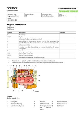
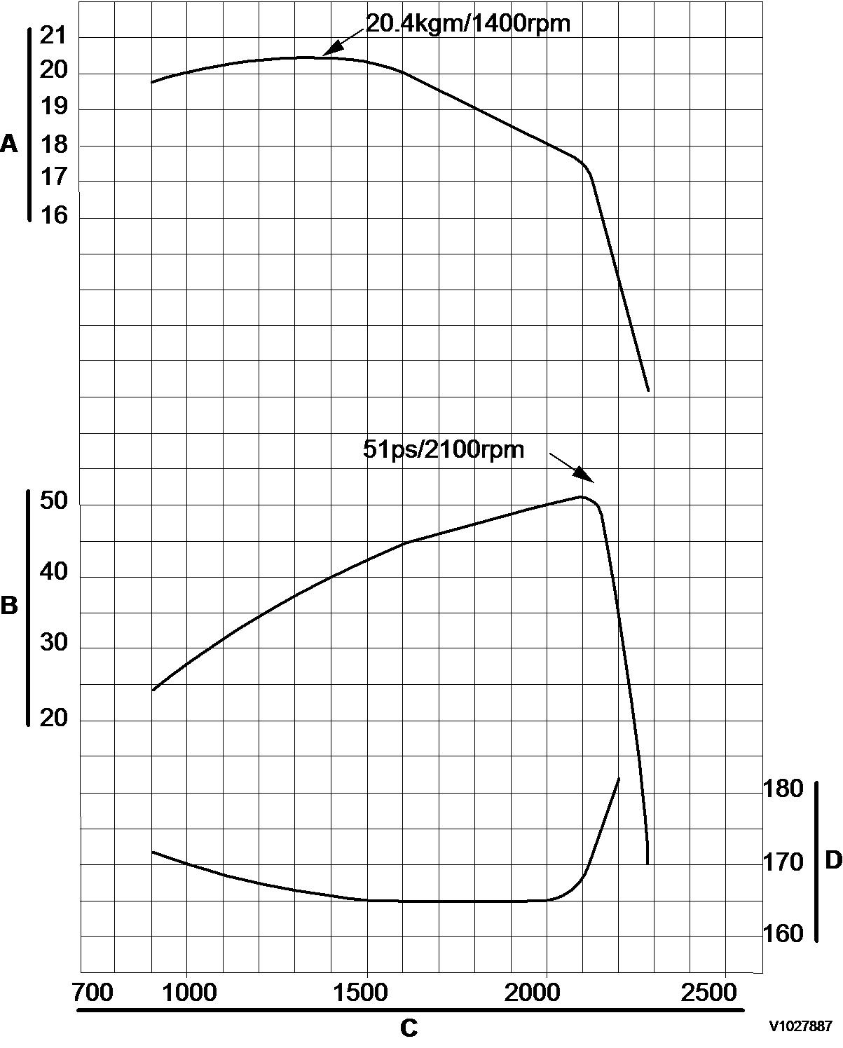
The engine is a 4–cycle, 4–cylinder, direct injected, water cooled diesel engine. The engine produces powerful performance using direct injection type combustion chamber.


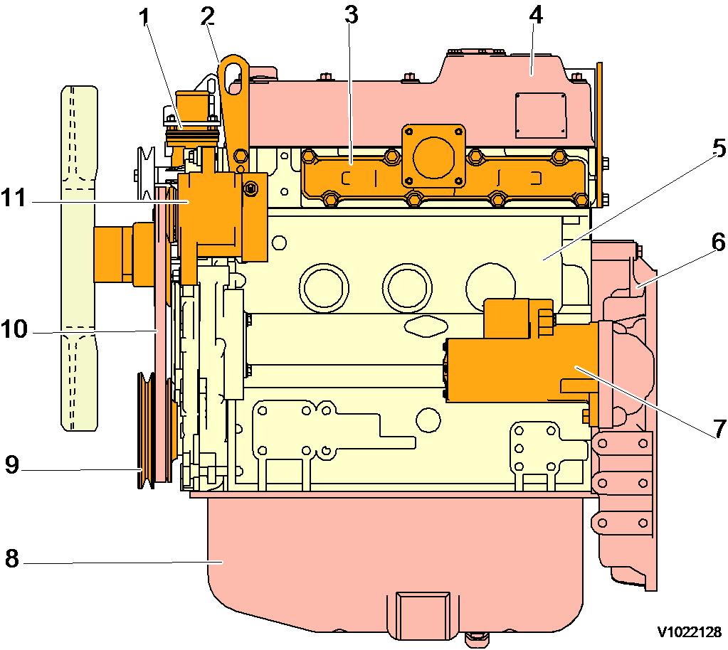
4 Engine, starter motor side view
1 Thermostat housing 7 Starter motor
2 Lifting eye 8 Engine oil pan
3 Exhaust manifold 9 Crankshaft V-pully
4 Rocker arm cover 10 V-belt
5 Cylinder block 11 Alternator 6 Flywheel housing
5
Document Title: Function Group: Information Type: Date: Engine, tightening torque 200 Service Information 2014/4/6 0
Profile: CEX, ECR58 [GB]
Engine, tightening torque
Tightening torque, unit: Nm (lbf ft)
Item
Lubricating oil application (thread portion, and seat surface)
Cylinder head screw M 11 × 1.25 103.1 ~ 112.9 (76 ~ 83) Applied
Connecting rod screw M10 × 1.0 53.9 ~ 58.8 (40 ~ 43) Applied
Flywheel set screw M14 × 1.5 186.2 ~ 205.8 (137 ~ 152) Applied
Bearing cap set screw M 11 × 1.25 108.1 ~ 117.9 (80 ~ 87) Applied
Crankshaft pulley set screw M14 × 1.5 107.9 ~ 127.5 (80 ~ 94) Applied
Fuel injection nozzle set screw M 8 × 1.25 22.6 ~ 28.4 (17 ~ 21) Not applied
Fuel feed pump drive gear set nut M 18 × 1.5 113 ~ 123 (83 ~ 90) Not applied
High-pressure fuel lines screw M 12 × 1.5 19.6 ~ 24.5 (174 ~ 217) Not applied
Fuel return pipe joint screw M 6 × 1.0 7.8 ~ 9.8 (70 ~ 86) Not applied
Tightening torque for standard screws and nuts, unit: Nm (lbf ft)
Item
M 6 × 1.0 9.8 ~ 11.8 (7 ~ 9)
oil application (thread portion, and seat surface)
Screw (7T) and nut
M 8 × 1.25 22.6 ~ 28.4 (17 ~ 21)
M 10 × 1.5 44.1 ~ 53.9 (33 ~ 40)
M 12 × 1.75 78.4 ~ 98 (58 ~ 72)
M 14 × 1.5 127.5 ~ 147.1 (94 ~ 108)
M 16 × 1.5 215.7 ~ 235.4 (157 ~ 174)
1/8 9.8 (7)
PT plug 1/4 19.6 (14) 3/8 29.4 (22) 1/2 58.5 (43)
Pipe joint screw
M 8 12.7 ~ 16.7 (9 ~ 12)
M 10 19.6 ~ 25.5 (14 ~ 19)
M 12 24.5 ~ 34.3 (18 ~ 25)
M 14 39.2 ~ 49 (29 ~ 36)
M 16 49 ~ 58.8 (36 ~ 43)
NOTE!
Lubricating oil is not applied to threaded portion and seat surface.
Use 80% of the value at left when the tightening part is aluminium.
Use 60% of the value at left for 4T screws and lock nuts.
Document Title: Function Group: Information Type: Date: Precautions 200 Service Information 2014/4/6 0
Profile: CEX, ECR58 [GB]
Precautions
Make preparation as follows before starting engine inspection and service.

WARNING
Risk of personal injury. Very heavy object.
Be sure to fix the engine securely to prevent injury or damage due to parts falling during the work.
WARNING
Risk of personal injury! Wear safety glasses and use protective gloves.
Always wear glasses or a protective face shield when using compressed air or steam to prevent any foreign matter from getting into the eyes.
Fix the engine on a horizontal base.
Remove the coolant hoses, fuel oil pipes, wire harness, control wires etc. connecting the driven machine and engine, and drain coolant, lubricating oil and fuel.
Remove soil, oil, dust, etc. from the engine by washing with solvent, air, steam, etc. Carefully operate so as not to let any foreign matter enter the engine.
Any part which is found defective as a result of inspection or any part whose measured value does not satisfy the standard or limit shall be replaced.
Any part predicted to dissatisfy the standard or limit before the next service as estimated from the state of use should be replaced even when the measured value then satisfies the standard or limit.
Document Title: Function Group: Information Type: Date:
Periodic inspection and maintenance procedure 200
Profile:
CEX, ECR58 [GB]
Periodic
Service Information 2014/4/6 0
inspection and maintenance procedure
Check before daily operation
Be sure to check the following points before starting the engine every day.
If any problem is found, do not use the machine before the engine repairs have been completed.
Oil leak from the lubrication system
Fuel leak from the fuel system
Coolant leak from the cooling system
Damaged parts
Loosened or lost screws
Fuel, radiator rubber hoses cracked, loosened clamp
Thermostat and Thermal Switch Inspection
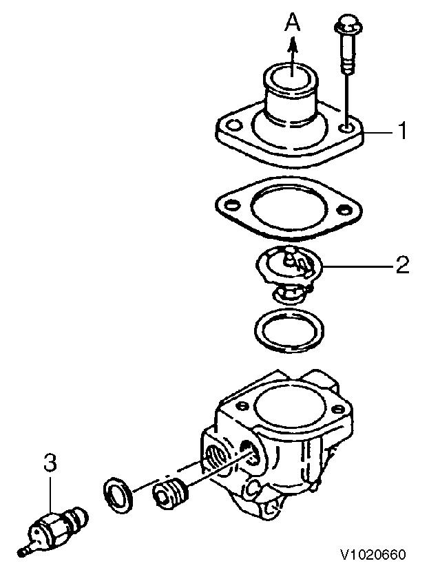
Thermostat switch A. To radiator 1.
Thermostat
Place the thermostat in a container filled with water.
Heat it while measuring the water temperature, and see that the thermostat is actuated at the temperature of following table.
NOTE!
Valve opening temperature is scribed on the flange.
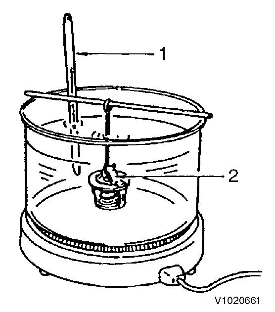
Figure 2
Thermostat inspection
1. 2. Thermometer
Thermostat
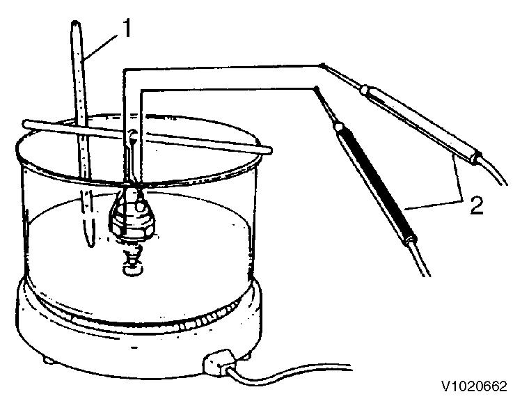
Figure 3
Thermostat switch inspection
1. 2. Thermometer Tester probes
Thermostat switch
Place the thermostat switch in a container filled with antifreeze or oil. Heat it while measuring the fluid temperature. The switch is normal if the multi-meter shows continuity when the fluid temperature is 107 ~ 113 °C (225 ~ 235 °F).
Inspection and replacement of fuel pipe and cooling pipes/hoses.
Regularly check the rubber hoses of the fuel system and cooling system. If cracked or degraded, replace them with new ones. Replace the rubber hoses at least every 2 years.
Lapping the intake and exhaust valves
The adjustment is necessary to maintain proper contact of the valves and seats.
Fuel injection timing inspection and adjustment
Sensor inspection
Oil pressure switch
Disconnect the connector from the oil pressure switch. Keep the multi-meter probes in contact with the switch terminal and cylinder block while operating the engine. If is abnormal if circuit is closed.
Thermostat switch
Coolant leak check in cooling system
Check coolant leakage from the cooling system visually. If any problem is found, Inspect as follows :
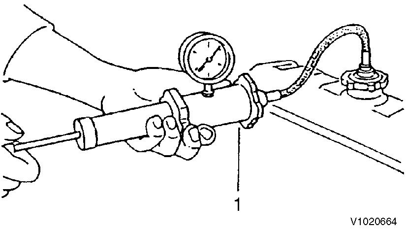
Figure 5
Water leak check in coolant system
1. Cap tester
Fill coolant to the normal level in the radiator, and install the cap tester on the radiator. Operate the manual pump to set the pressure to 0.9 ± 0.15 kgf/cm2(12.8 ± 2.1 psi). If the cap tester pressure gage reading drops then, coolant is leaking from the cooling system. Check and repair the coolant leaking point.
Radiator cap inspection
6
Radiator cap inspection
1. Radiator cap
Install the radiator cap on the cap tester. Set the tester pressure to 0.9 ± 0.15 kgf/cm2(12.8 ± 2.1 psi) and check that the cap relief valve is opened. If the relief valve does not open, replace the cap since it is abnormal.
Document Title: Function Group: Information Type: Date: Compression pressure inspection 210
Service Information 2014/4/6 0
Profile:
CEX, ECR58 [GB]
Compression pressure inspection
Compression pressure drop is one of major causes of increasing blow-by gas (lubricating oil contamination or increased lubricating oil consumption as a resultant phenomenon) or starting failure. The compression pressure is affected by the following factors:
Degree of clearance between piston and cylinder
Degree of clearance at intake/exhaust valve seat
Gas leak from nozzle gasket or cylinder head gasket
In other words, the pressure drops due to increased parts wear and reduced durability resulting from long use of the engine. A pressure drop may also be caused by scratched cylinder or piston by dust entrance from the dirty air cleaner element or worn or broken piston ring. Measure the compression pressure to diagnose presence of any abnormality in the engine.
Compression pressure measurement method
After warming up the engine, remove the fuel injection nozzle from the cylinder to be measured.

Figure 1
Measuring the compression pressure
1. Compression gauge
Crank the engine before installing the compression gauge adapter.
Perform cranking with the stop handle at the stop position (no injection state).
Install the compression gauge and compression gauge adapter at the cylinder to be measured.
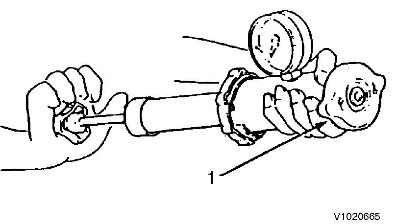
NOTE!
Do not forget to install a gasket at the tip end of the adapter.
Crank the engine by the starting motor until the compression gage reading is stabilized.
Standard compression pressure
Standard: 3.43 ±0.098 MPa (35 ±1 kgf/cm2) (498 ±14 psi) (34.32 ±0.98 bar)
Limit: 2.74 MPa (28 kgf/cm2) (398 psi) (27.4 bar)
Dispersion among cylinders: 0.19 ~ 0.29 MPa (2 ~ 3 kgf/cm2) (28 ~ 43 psi) (1.96 ~ 2.94 bar)
Engine speed and compression pressure
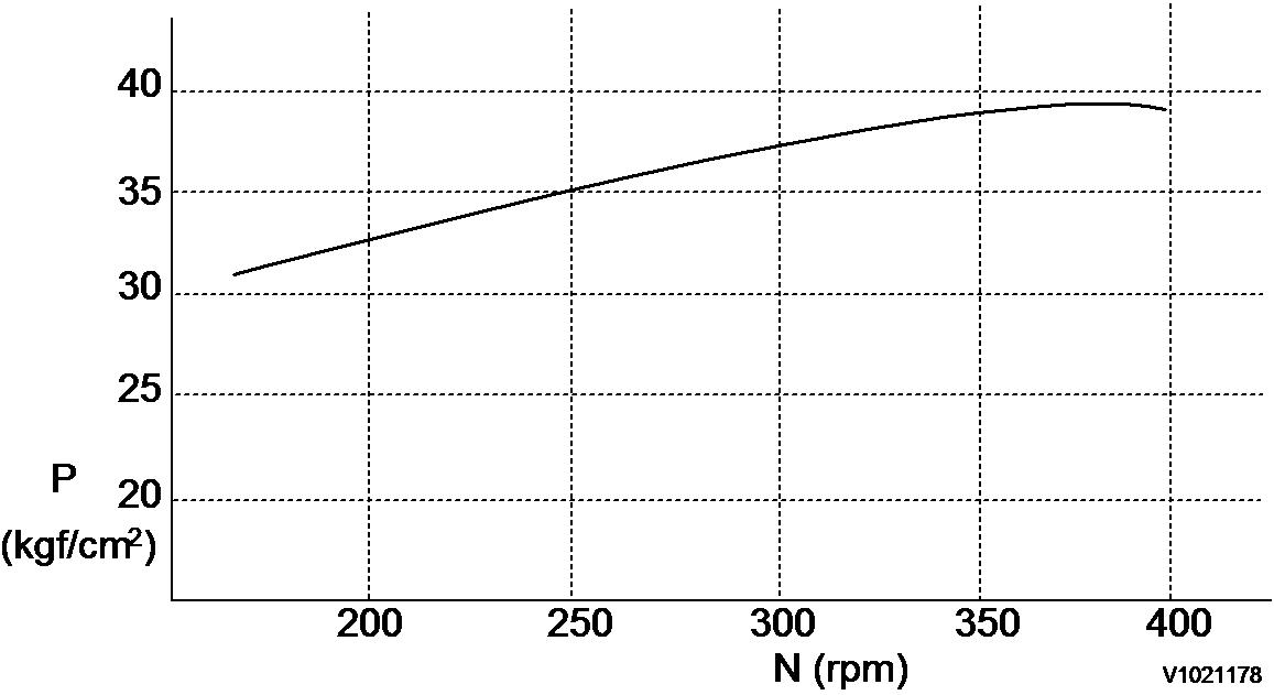
Figure 2
Engine speed and compression pressure
P: Compression pressure
N: Engine speed
Check items
When the measured compression pressure is below the limit value, inspect each part by referring to the table below.
Compression pressure check items
Item Cause
Air cleaner element
Clogged element Broken element Defect at element seal portion
Valve clearance
Valve timing
Cylinder head gasket
Corrective action
Clean the element. Replace the element.
Excessive or no clearance Adjust the valve clearance.
Incorrect valve clearance
Adjust the valve clearance.
Gas leak from gasket
Inlet/exhaust valve
Valve seat
Piston ring Cylinder
Gas leak due to worn valve seat or foreign matter Sticking valve
Replace the gasket. Retighten the cylinder head screws to the specified torque.
Lap the valve seat. Replace the inlet/exhaust valve.
Gas leak due to scoring or wear Perform honing or boring/honing and use an oversized part.
Document Title: Function Group: Information Type: Date:
Adjusting operation 210
Profile: CEX, ECR58 [GB]
Adjusting operation
Service Information 2014/4/6 0
Perform adjusting operation as follows after the maintenance job:
Supply the fuel oil, lubricating oil and coolant.
NOTE!
Check the levels of the lubricating oil and coolant again after test running (for about 5 minutes) and add as required.
Start the engine, and carry out idling at a low revolution (700 ~ 900 rpm) for a few minutes.
Run in the engine for about five minutes at the rated revolution (no–load). Check for coolant, fuel or oil leaks and existence of abnormal vibration or noise. Also check the oil pressure, coolant temperature and exhaust gas color. Adjust the no–load minimum and maximum revolutions according to the specifications. Perform loaded operation as required.
Long storage
Observe the following instructions when the engine is to be stored for a long period without operation:
Always drain coolant in a cold season or before extended storage. (This is unnecessary when antifreeze is used.)
NOTE!
Negligence of water draining will cause the water remaining inside the engine to freeze and expanded, damaging the engine cooling system components.
Coolant draining procedure
1. 2. 3. 4.
Remove the radiator cap.
Loosen the draining cock under the radiator to drain coolant.
Loosen the drain cock on the side of the engine block to drain coolant.
After draining coolant, tighten the radiator cap and drain plug and cocks.
Remove all mud, dust, oil deposits and thoroughly clean the engine and attached components. Perform the nearest periodic inspection before the storage.
Drain or fill the fuel oil fully to prevent condensation in the fuel tank.
Disconnect the battery cable from the battery negative terminal.
Cover the silencer, air cleaner and electric parts with PVC cover to prevent water and dust from depositing or entrance.
Select a well–ventilated location without moisture and dust for storage. Perform battery recharging once a month during storage to compensate for self–discharge.
Checking and adjusting radiator fan V-belt
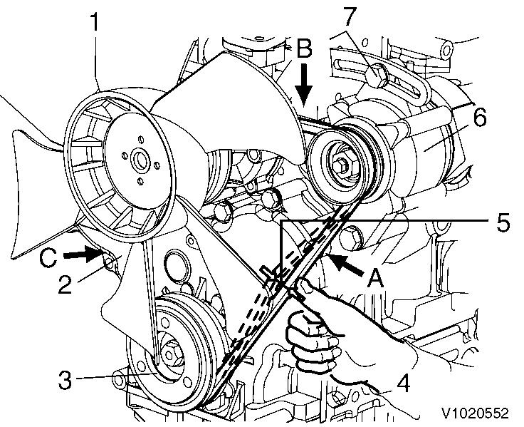
1
Checking and adjustment, radiator fan V-belt
Radiator fan
V-belt
Crankshaft V-pulley
Press with thumb
Deflection
Alternator
Set screw
When there is not enough tension in the V-belt, the V-belt will slip making it impossible for the alternator to generate power and water pump and cooling fan will not work causing the engine to overheat. Check and adjust the V-belt tension (deflection) in the following manner.
Press the V-belt with your thumb [approximately 98N (10kgf)] at the middle of the V-belt span to check the tension (deflection).
Available positions to check and adjust the V-belt tension (deflection) are at the A, B or C direction as shown in the illustration right.
You may choose a position whichever you can easily carry out the check and adjustment on the machine unit.
"New V-belt" refers to a V-belt which has been used less than 5 minutes on a running engine.
"Used V-belt" refers to a V-belt which has been used on a running engine for 5 minutes or more. The specified deflection to be measured at each position should be as follows.
V-belt deflection, unit: mm (in)
For used V-belt
~ 14
~ 0.55)
~ 10
~ 0.39
~ 13
~ 0.51) For new V-belt
~ 12 (0.31 ~ 0.47)

2
Adjustment, V-belt tension
~ 8
~ 0.31)
~ 11
~ 0.43)
A.
B. C. Bar Adjuster Alternator
If necessary, adjust the V-belt tension (deflection).
To adjust the V-belt tension, loosen the set screw and move the alternator to tighten the V-belt.
After replacing with a new V-belt and adjusting it, run the engine for 5 minutes and readjust the deflection to the value in the table above.
Visually check the V-belt for cracks, oiliness or wear.
If any, replace the V-belt with a new one.
Inspection and adjustment: Injection pressure and spray pattern of fuel injection valve
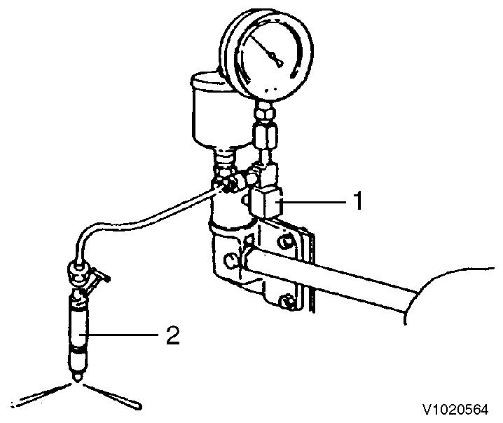
Figure 3
Injection pressure measurement
1. 2. Nozzle tester Injection nozzle
Injection pressure measurement : 225 ± 5 kgf/cm2 (3200 ± 71 psi)
Remove carbon deposit at the nozzle hole thoroughly before measurement.
Connect the fuel injection valve to the high pressure pipe of the nozzle tester.
Operate the nozzle tester lever slowly and read the pressure at the moment when the fuel injection from the nozzle starts.
If the measured injection pressure is lower than the standard level, replace the pressure adjusting shim with a thicker one.
Injection pressure adjustment
Type of pressure adjusting shim thickness, mm (in)
0.13(0.0051), 0.15(0.0059), 0.18(0.0071), 0.4(0.0157), 0.5(0.0197), 0.8(0.0315)
Injection pressure adjustment
The injection pressure is increased by approximately 19 kgf/cm2 (270 psi) when the adjusting shim thickness is increased by 0.1 mm (0.004).
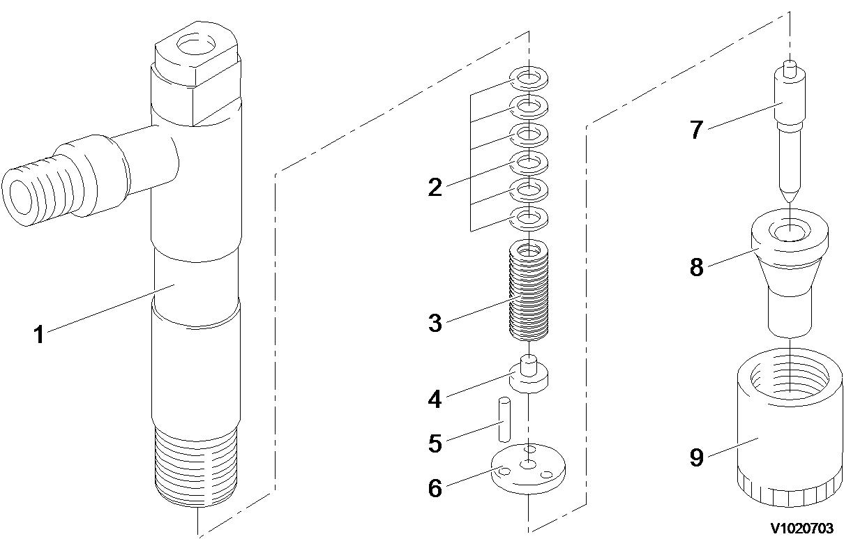
Figure 4
Exploded view, fuel injection valve
1 Nozzle holder
2 Pressure adjusting shim
3 Nozzle spring
4 Nozzle spring seat
5 Dowel pin
6 Valve stop spacer
7 Nozzle valve
8 Nozzle body
9 Nozzle case nut (tightening torque : 4.25 ± 0.25 kgf·m (30.7 ± 1.8 lbf·ft)
Spray pattern inspection
After adjustment to the specified valve opening pressure, use a nozzle tester and check the spray pattern and seat oil-tightness.
1.
Seat oil tightness check
After injecting a few times, increase the pressure gradually. Hold the pressure for about 5 seconds at a little before the valve opening pressure of 20 kgf/cm2 (285 psi), and check to see that oil does not drip from the tip end of the nozzle. If extreme oil leak from the overflow joint exists during injection by the nozzle tester, check after retightening. If excessive oil is leaking, replace the nozzle assembly.
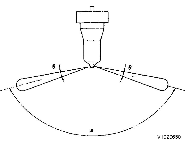
Uniform spray pattern from each nozzle (normal)
Spray and injection states
Operate the nozzle tester lever at a rate of once or twice a second and check for abnormal injection.
If normal injection as shown below cannot be obtained, replace the fuel injection valve.
- No extreme difference in angle (θ)
- No extreme injection angle difference (α)
- Finely atomized spray
- Excellent spray departure
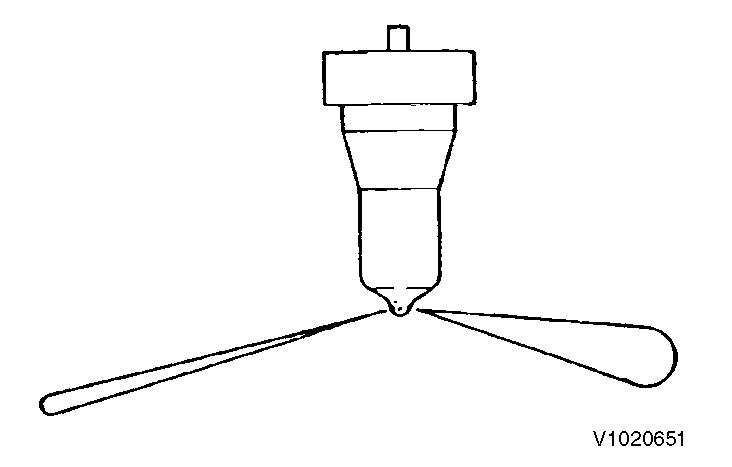
Figure 6
Non-uniform spray pattern from each nozzle (abnormal)
Nozzle valve sliding test
Wash the nozzle valve in clean fuel oil.
Place the nozzle body vertically and insert the nozzle into the body to about 1/3 of its length.
The valve is normal if it smoothly falls by its own weight into the body.
In case of a new nozzle, remove the seal peel, and immerse it in clean diesel oil or the like to clean the inner and outer surfaces and to thoroughly remove rust-preventive oil before using the nozzle.
NOTE!
New nozzle is coated with rust-preventive oil and is pasted with the seal peel to shut off outer air.
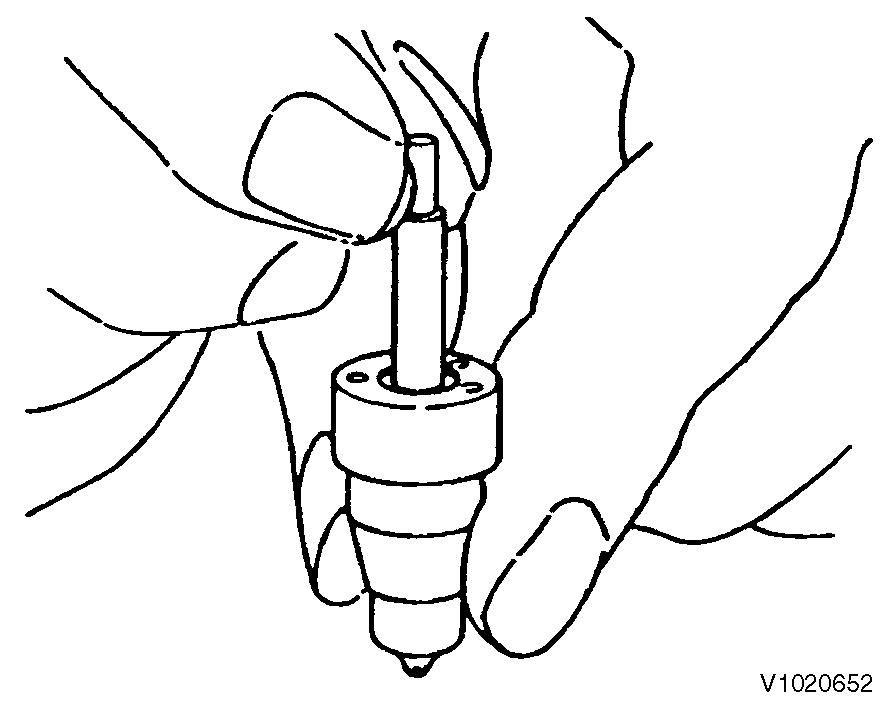
Figure 7
Nozzle valve sliding check by gravity
The type of nozzle can be determined from the number inscribed on the outside of the nozzle body.
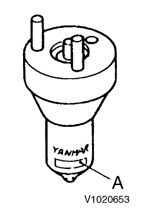
Figure 8
Nozzle body identification number
A. Identification number
Nozzle body identification number
Symbol Description Remarks
Y YANMAR
DLL Type (DLL : semi-long type)
A Nozzle insertion angle
Code A : angled
No code : no angle
150 Injection angle
P Nozzle size : size P, size S
244JO Design code
Measuring and adjusting valve clearance
Make measurement and adjustment while the engine is cold.
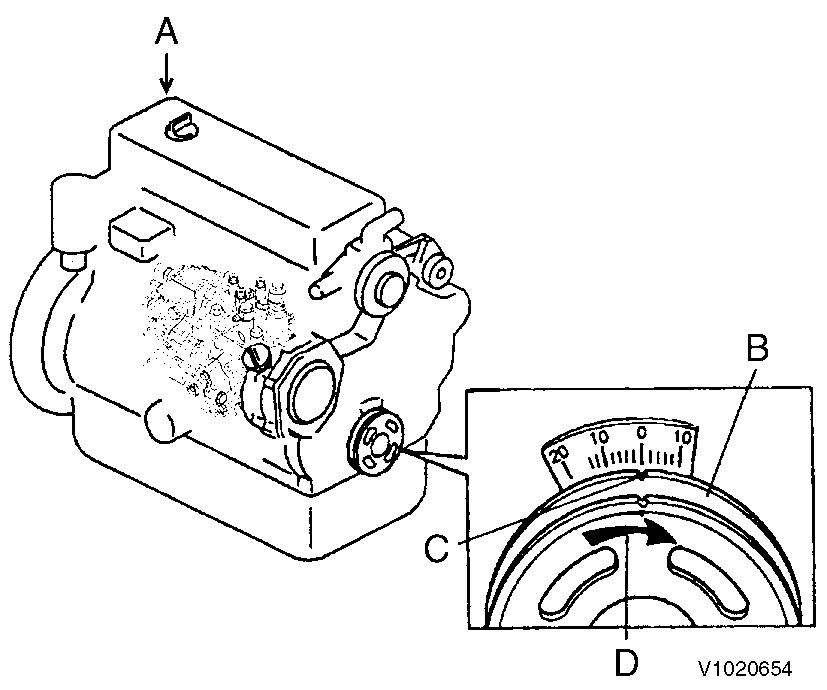
9
Valve clearance measurement
A. B. C. D. No.1 cylinder Crankshaft pulley Top mark Rotational direction
1. Valve clearance measurement
Remove the rocker cover on cylinder head.
Turn the crankshaft to bring the piston of the No.1 cylinder to its compression top dead center while watching the rocker arm motion, timing scale and the top mark position of the crankshaft pulley.
(Position where both the intake and exhaust valves are closed.)
NOTE!
The crankshaft shall be turned clockwise as viewed from the pulley side.
NOTE!
The No.1 cylinder position is on the flywheel side and the ignition order shall be 1-3-4-2-1 at 180° intervals.
NOTE!
Since the intake and exhaust valve rocker arms are operated the same and there is a clearance between the arm and valve generally at the top dead center, the position can be checked by means of the play when the arm head is held with a hand. Also see that the crankshaft pulley top mark is positioned at zero on the timing scale. If there is no valve clearance, inspection in the disassembled state is necessary since the valve seat may be worn abnormally.
Insert a thickness gage between the rocker arm and valve cap in case of 2-valve cylinder head, or insert between the rocker arm and the valve bridge in case of 4-valve head, and record the measured valve clearance. (Use it as the data for estimating the wear state.)
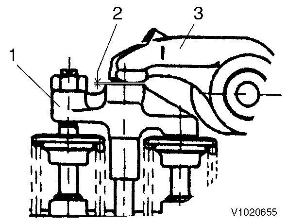
Figure 10
Valve clearance
1. 2. 3. Valve bridge Valve clearance Rocker arm
Turn the crankshaft 180° then and make adjustment for the No.3 cylinder. Then adjust the No.4 and No.2 cylinders in this order.
The cylinder to be adjusted first does not have to be the No.1 cylinder. Select and adjust the cylinder where the piston is the nearest to the top dead center after turning, and make adjustment for other cylinders in the order of ignition by turning the crankshaft 180° each time.
2.
Valve clearance inspection and adjustment
In case of 4-valve cylinder head loosen the lock nut and adjusting screw of rocker arm. Be careful that excessive tension isn"t applied to the valve bridge, and loosen a lock nut of valve bridge.
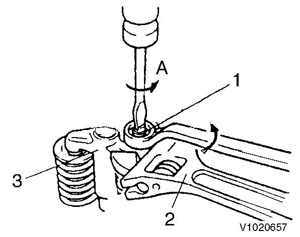
Figure 12
Adjustment, screw
1. 2. 3. Adjusting screw Wrench Valve bridge
A. Loosen
NOTE!
When loosening a lock nut of a valve bridge, loosen the lock nut while holding the valve bridge with a wrench so that the valve bridge can not lean.
Insert a 0.2 or 0.3 mm thickness gage between the rocker arm and valve cap / valve bridge, and adjust the valve clearance. Tighten the adjusting screw. Recheck the valve clearance.
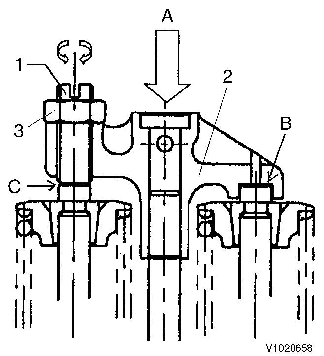
Figure 13
Adjustment, valve clearance
1. 2. 3. Adjusting screw Valve bridge Rocker nut
A. B. C. Hold Clearance 0 Adjust clearance to 0
Apply oil to the contact surface between adjusting screw and push rod.
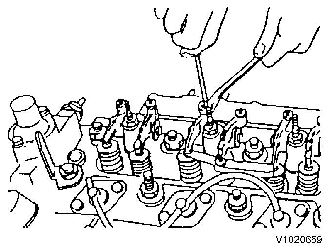
Figure 14
Adjustment, valve clearance
Turn the crankshaft 180° then and make adjustment for the No.3 cylinder. Then adjust the No.4 and No.2 cylinders in this order.
The cylinder to be adjusted first does not have to be the No.1 cylinder. Select and adjust the cylinder where the piston is the nearest to the top dead center after turning, and make adjustment for other cylinders in the order of ignition by turning the crankshaft 180° each time.
Adjusting the no-load maximum or minimum speed
After warming the engine, gradually raise the speed and set it at the no-load maximum revolution.

Suggest:
If the above button click is invalid.
Please download this document first, and then click the above link to download the complete manual.
Thank you so much for reading
15
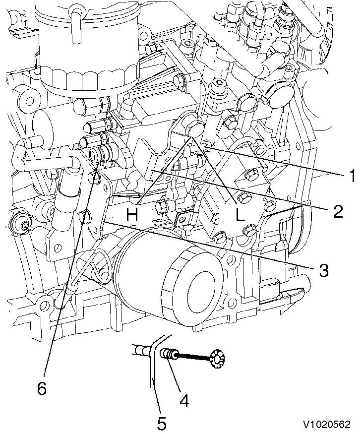
Adjustment, governor lever and accelerator device
1 Low idle limiting screw
2 Governor lever
3 Accelerating cable bracket
4 Accelerating cable fixing nut
5 Accelerating cable bracket
6 High idle limiting screw
H High
L Low
If the no-load maximum revolution is out side the standard range, adjust it by turning the high idle limiting screw. Then set the no-load minimum speed by adjusting the low idle limiting screw.