
DOWNLOAD PARTS MANUAL
DOWNLOAD SERVICE MANUAL
Service Information
DocumentTitle: FunctionGroup: InformationType: Date: Foreword additional 000 ServiceInformation 2015/5/29

Service manual Demolition machine
Profile:
EXC, EC460B LC [GB]
Foreword additional Service manual Demolition machine
This Service manual for Demolition machine built on base machines EC210B, EC240B, EC290B and EC360B
NOTE!
This is an additionalService manual and should be used together with the Service manual for the base machine.
See Operator’s manual for dimensions and weights for the complete machine. Service work on the machine must not be carried out before the instructions in Section "Safety" in both this Service manual and in the base machine Service manual.
For manual reference numbers, see current publications catalogue and SSI (Service Support Information). The operation numbers refer to "Time Guide". The instructions are based on the use of special tools, E-tools and generally available standard tools.
For supplementary information on special tools, see "Special tools.” Drawings for E-tools can be found in Section 0 (08) General.
Volvo will not accept any responsibility if any lifting devices, tools or work methods other than those described in this publication are used.
The information and data given in this manual are valid at the time of publication. We reserve the right to modify specifications and equipment without prior notification.
Service Information
DocumentTitle: FunctionGroup: InformationType: Date:
Profile: EXC,EC460BLC[GB]
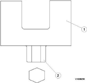
Component locations

Figure1

Service Information
DocumentTitle: FunctionGroup: InformationType: Date:
Demolition machine, 000 ServiceInformation 2015/5/29 description

Profile: EXC,EC460BLC[GB]
Demolition machine, description
The demolition machine is based on a standard machine.
This demolition machine is composed of HD Side door reinforce, Slew ring gear protection cover, Upper frame side protection plate reinforce, Upper under cover reinforce, Boom cylinder protection plate and Bucket cylinder protection plate, Working and maintenance lamps, Top protection round pipe on rear and RH side. See machine view 000 Machine view, demolition

Machine view, demolition
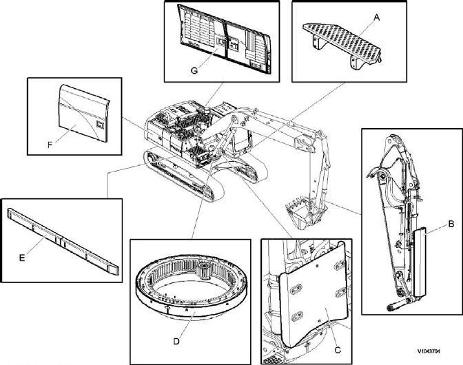
Machineview,demolition
Figure1
A. Step, Cabin
B. Bucket cylinder protecting guard
C. Boom cylinder protecting guard
D. Swing ring gear cover
E. Side impact protection
F. Auxiliary hood, right side door
G. Auxiliary hood, left side door
Machine view, demolition

Machineview,demolition
Figure1
A. Auxiliary hood, left side door
B. Step, Cabin
C. Bucket cylinder protecting guard
D. Boom cylinder protecting guard
E. Swing ring gear cover
F. Auxiliary hood, right side door
DocumentTitle: FunctionGroup: Machine handler view, waste 000
Service Information
Profile: EXC,EC460BLC[GB]
Machine view, waste handler
InformationType: ServiceInformation Date: 2015/5/29

Figure1
Componentspositiononmachine
1. Fire extinguisher fault indicator and battery disconnect switch
2. Manual actuation switch
3. Swing ring gear cover
4. Cab air filtering system
5. Dual stage pre-cleaner
6. Fire extinguisher system
7. Reversible cooling fan system
8. Nozzle: Engine section (4EA), Hydraulic (2EA)
9. Agent cylinder
Service Information

DocumentTitle: FunctionGroup: InformationType: Date: NET 8940-00240 Replace tool for the hydraulic tee fitting
Profile: EXC,EC460BLC[GB] 080
ServiceInformation 2015/5/29
NET 8940-00240 Replace tool for the hydraulic tee fitting