
Document Title: Function Group: Information Type: Date: Engine, description 200 Service Information 2014/4/17
Profile: CEX, EC17C [GB]
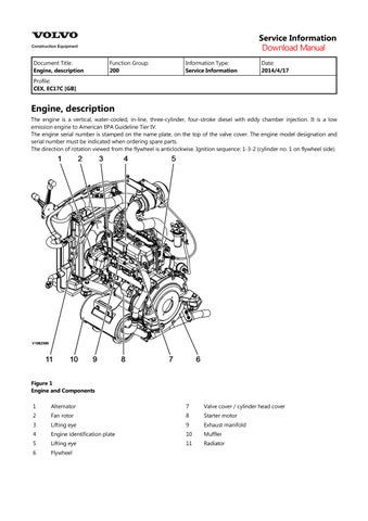
Engine, description
The engine is a vertical, water-cooled, in-line, three-cylinder, four-stroke diesel with eddy chamber injection. It is a low emission engine to American EPA Guideline Tier IV.
The engine serial number is stamped on the name plate, on the top of the valve cover. The engine model designation and serial number must be indicated when ordering spare parts.
The direction of rotation viewed from the flywheel is anticlockwise. Ignition sequence: 1-3-2 (cylinder no. 1 on flywheel side).


2
and Components 1 Main fuel filter
Injection pump
Service Information
Document Title: Function Group: Information Type: Date:
Troubleshooting chart 200
Profile:
CEX, EC17C [GB]
Troubleshooting chart
Service Information 2014/4/17
The following table summarizes the general trouble symptoms and their causes. If any trouble symptom occurs, take corrective action before it develops into a serious problem so as not to shorten the engine service life.
Engine troubleshooting chart
Trouble symptoms Causes
Engine does not start
Improper clearance of inlet/exhaust valve
Seizure of inlet/exhaust valve
Seized or broken piston ring
Worn piston ring, piston or cylinder
Seized crankpin metal or bearing
Foreign matter trapped in combustion chamber
Improper open/close timing of intake/exhaust valves
Improper properties of lubricating oil
Water entrance in fuel system
Clogged fuel filter
Air entrance in fuel system
Clogged or cracked fuel pipe
Insufficient fuel supply to fuel injection pump
Priming failure (foreign matter trapped in the valve inside the priming pump)
Starting motor defect
Alternator defect
Open circuit in wiring harness
Battery voltage drop
Engine starts, but stops soon.
Exhaust smoke none.
Engine starts, but stops soon.
Exhaust smoke excessive.
Improper clearance of inlet/exhaust valve
Seized crankpin metal or bearing
Improper arrangement of piston rings joint
Defective governor
Improper properties of lubricating oil
Insufficient lubricating oil level
Clogged fuel filter
Air entrance in fuel system
Clogged or cracked fuel pipe
Insufficient fuel supply to fuel injection pump
Seizure of inlet/exhaust valve
Seized or broken piston ring
Worn piston ring, piston or cylinder
Water entrance in fuel system
Corrective actions
Adjust the valve clearance
Correct or replace
Replace the piston ring
Perform honing and use oversize parts
Repair or replace
Disassemble and repair
Adjust the valve clearance
Use proper lubricating oil
Perform draining from the fuel filter
Clean or replace
Perform air bleeding
Clean or replace
Check the fuel tank cock, fuel tank, fuel pipe and fuel feed pump
Disassemble and clean
Repair or replace
Repair or replace
Repair
Inspect and charge the battery
Adjust the valve clearance
Repair or replace
Correct the ring joint positions
Make adjustment
Use proper lubricating oil
Add proper lubricating oil
Clean or replace
Perform air bleeding
Clean or replace
Check the fuel tank cock, fuel tank, fuel pipe and fuel feed pump
Correct or replace
Replace the piston ring
Perform honing and use oversize parts
Perform draining from the fuel filter
Insufficient engine output.
Exhaust color : ordinary
Insufficient engine output.
(Exhaust color : white)
Clogged air filter
Improper clearance of inlet/exhaust valve
Compression leakage from valve seat
Seizure of inlet/exhaust valve
Blowout from cylinder head gasket
Worn crankpin and journal bearing
Improper properties of lubricating oil
Improper properties of fuel oil
Clogged fuel filter
Air entrance in fuel system
Clogged or cracked fuel pipe
Insufficient fuel supply to fuel injection pump
Clogged strainer at fuel feed pump inlet
Seized or broken piston ring
Worn piston ring, piston or cylinder
Improper arrangement of piston rings joint
Reverse assembly of piston ring
Worn inlet/exhaust valve guide
Improper open/close timing of intake/exhaust valves
Timing of fuel injection pump too late
Improper properties of fuel oil
Water entrance in fuel system
Uneven injection volume of fuel injection pump
Poor spray pattern from fuel injection nozzle
Clean
Adjust the valve clearance
Lap the valve seat
Correct or replace
Replace the gasket
Measure and replace
Use proper lubricating oil
Use proper fuel oil
Clean or replace
Perform air bleeding
Clean or replace
Check the fuel tank cock, fuel tank, fuel pipe and fuel feed pump
Clean the strainer
Replace the piston ring
Perform honing and use oversize parts
Correct the ring joint positions
Reassemble correctly
Measure and replace
Adjust the valve clearance
Check and adjust
Use proper fuel oil
Perform draining from the fuel filter
Check and adjust
Check and adjust
Insufficient engine output.
(Exhaust color : black)
Poor exhaust color : white (During work)
Compression leakage from valve seat
Seizure of inlet/exhaust valve
Improper open/close timing of intake/exhaust valves
Insufficient cooling effect of radiator, Defective thermostat (kept opened) or slipping fan belt
Insufficient coolant level
Slackened fan belt
Defective thermostat
Timing of fuel injection pump too late
Improper properties of fuel oil
Uneven injection volume of fuel injection pump
Poor spray pattern from fuel injection nozzle
Clogged air filter
Engine used at high temperature or at high altitude
Clogged exhaust pipe
Seized or broken piston ring
Worn piston ring, piston or cylinder
Reverse assembly of piston ring
Improper open/close timing of intake/exhaust valves
Excessive cooling effect of radiator,
Lap the valve seat
Correct or replace
Adjust the valve clearance
Repair or replace thermostat and fan belt
Check leakage from cooling system
Adjust the belt tension
Check or replace
Check and adjust
Use proper fuel oil
Check and adjust
Check and adjust
Clean
Study output drop and load matching
Clean
Replace the piston ring
Perform honing and use oversize parts
Reassemble correctly
Adjust the valve clearance
Repair or replace
Poor exhaust color : black
(During work)
Defective thermostat (kept closed)
Defective thermostat
Timing of fuel injection pump too early
Timing of fuel injection pump too late
Improper properties of fuel oil
Water entrance in fuel system
Uneven injection volume of fuel injection pump
Poor spray pattern from fuel injection nozzle
Compression leakage from valve seat
Seizure of inlet/exhaust valve
Improper open/close timing of intake/exhaust valves
Timing of fuel injection pump too early
Timing of fuel injection pump too late
Improper properties of fuel oil
Uneven injection volume of fuel injection pump
Excessive fuel injection volume
Poor spray pattern from fuel injection nozzle
Clogged air filter
Engine used at high temperature or at high altitude
Clogged exhaust pipe
High knocking sound during compression
Abnormal engine sound
Uneven combustion sound
Timing of fuel injection pump too early
Improper clearance of inlet/exhaust valve
Compression leakage from valve seat
Seizure of inlet/exhaust valve
Seized or broken piston ring
Seized crankpin metal or bearing
Worn crankpin and journal bearing
Loosened connecting rod screw
Foreign matter trapped in combustion chamber
Excessive gear backlash
Improper open/close timing of intake/exhaust valves
Improper properties of fuel oil
Water entrance in fuel system
Uneven injection volume of fuel injection pump
Poor spray pattern from fuel injection nozzle
Clogged air filter
Clogged exhaust pipe
Hunting during idling
Seized or broken piston ring
Seized crankpin metal or bearing
Worn crankpin and journal bearing
Defective governor
Water entrance in fuel system
Uneven injection volume of fuel injection pump
Poor spray pattern from fuel injection nozzle
Check or replace
Check and adjust
Check and adjust
Use proper fuel oil
Perform draining from the fuel filter
Check and adjust
Check and adjust
Lap the valve seat
Correct or replace
Adjust the valve clearance
Check and adjust
Check and adjust
Use proper fuel oil
Check and adjust
Check and adjust
Check and adjust
Clean
Study output drop and load matching
Clean
Check and adjust
Adjust the valve clearance
Lap the valve seat
Correct or replace
Replace the piston ring
Repair or replace
Measure and replace
Tighten to specified torque
Disassemble and repair
Adjust gear and repair
Adjust the valve clearance
Use proper fuel oil
Perform draining from the fuel filter
Check and adjust
Check and adjust
Clean
Clean
Replace the piston ring
Repair or replace
Measure and replace
Make adjustment
Perform draining from the fuel filter
Check and adjust
Check and adjust
Hunting during work
Seizure of inlet/exhaust valve
Correct or replace
Large engine vibration
Seized crankpin metal or bearing
Worn crankpin and journal bearing
Defective governor
Water entrance in fuel system
Uneven injection volume of fuel injection pump
Poor spray pattern from fuel injection nozzle
Seizure of inlet/exhaust valve
Seized or broken piston ring
Seized crankpin metal or bearing
Worn crankpin and journal bearing
Loosened connecting rod screw
Defective governor
Timing of fuel injection pump too early
Uneven injection volume of fuel injection pump
Poor spray pattern from fuel injection nozzle
Repair or replace
Measure and replace
Make adjustment
Perform draining from the fuel filter
Check and adjust
Check and adjust
Correct or replace
Replace the piston ring
Repair or replace
Measure and replace
Tighten to specified torque
Make adjustment
Check and adjust
Check and adjust
Check and adjust
Difficulty in returning to low speed
Excessive fuel consumption
Excessive lubricating oil consumption
Defective governor
Compression leakage from valve seat
Excessive cooling effect of radiator,
Defective thermostat (kept closed)
Timing of fuel injection pump too late
Excessive fuel injection volume
Poor spray pattern from fuel injection nozzle
Engine used at high temperature or at high altitude
Seized or broken piston ring
Worn piston ring, piston or cylinder
Improper arrangement of piston rings joint
Reverse assembly of piston ring
Foreign matter trapped in combustion chamber
Worn inlet/exhaust valve guide
Improper properties of lubricating oil
Leakage from lubricating oil piping system
Excessive fuel injection volume
Lubricating oil diluted by fuel
Seizure of inlet/exhaust valve
Seized or broken piston ring
Worn piston ring, piston or cylinder
Lubricating oil mixed with water
Low lubricating oil pressure
Excessive blow-by gas
Blowout from cylinder head gasket
Cracked water jacket
Worn crankpin and journal bearing
Loosened connecting rod screw
Cracked water jacket
Improper properties of lubricating oil
Leakage from lubricating oil piping system
Insufficient delivery capacity of trochoid pump
Clogged lubricating oil filter
Defective pressure regulating valve
Insufficient lubricating oil level
Compression leakage from valve seat
Make adjustment
Lap the valve seat
Repair or replace
Check and adjust
Check and adjust
Check and adjust
Study output drop and load matching
Replace the piston ring
Perform honing and use oversize parts
Correct the ring joint positions
Reassemble correctly
Disassemble and repair
Measure and replace
Use proper lubricating oil
Repair
Check and adjust
Correct or replace
Replace the piston ring
Perform honing and use oversize parts
Replace the gasket
Repair or replace
Measure and replace
Tighten to specified torque
Repair or replace
Use proper lubricating oil
Repair
Check and repair
Clean or replace
Check, adjust or replace
Add proper lubricating oil
Lap the valve seat
Overheating of coolant
Seizure of inlet/exhaust valve
Seized or broken piston ring
Worn piston ring, piston or cylinder
Seized crankpin metal or bearing
Improper arrangement of piston rings joint
Reverse assembly of piston ring
Foreign matter trapped in combustion chamber
Worn inlet/exhaust valve guide
Improper properties of lubricating oil
Clogged lubricating oil filter
Excessive fuel injection volume
Blowout from cylinder head gasket
Seized or broken piston ring
Insufficient cooling effect of radiator, Defective thermostat (kept opened) or slipping fan belt
Insufficient coolant level
Cracked water jacket
Slackened fan belt
Defective thermostat
Excessive fuel injection volume
Engine used at high temperature or at high altitude
Correct or replace
Replace the piston ring
Perform honing and use oversize parts
Repair or replace
Correct the ring joint positions
Reassemble correctly
Disassemble and repair
Measure and replace
Use proper lubricating oil
Clean or replace
Check and adjust
Replace the gasket
Replace the piston ring
Repair or replace thermostat and fan belt
Check leakage from cooling system
Repair or replace
Adjust the belt tension
Check or replace
Check and adjust
Study output drop and load matching
Low coolant temperature
Air inlet pressure drop
Air inlet pressure rise
Exhaust temperature rise
Excessive cooling effect of radiator, Defective thermostat (kept closed)
Defective thermostat
Improper clearance of inlet/exhaust valve
Compression leakage from valve seat
Seizure of inlet/exhaust valve
Clogged air filter
Engine used at high temperature or at high altitude
Excessive fuel injection volume
Improper clearance of inlet/exhaust valve
Compression leakage from valve seat
Seized or broken piston ring
Insufficient cooling effect of radiator, Defective thermostat (kept opened) or slipping fan belt
Insufficient coolant level
Slackened fan belt
Timing of fuel injection pump too late
Uneven injection volume of fuel injection pump
Excessive fuel injection volume
Clogged exhaust pipe
Repair or replace
Check or replace
Adjust the valve clearance
Lap the valve seat
Correct or replace
Clean
Study output drop and load matching
Check and adjust
Adjust the valve clearance
Lap the valve seat
Replace the piston ring
Repair or replace thermostat and fan belt
Check leakage from cooling system
Adjust the belt tension
Check and adjust
Check and adjust
Check and adjust
Clean
Document Title: Function Group: Information Type: Date: Engine, removing 210 Service Information 2014/4/17
Profile: CEX, EC17C [GB]
Engine, removing
Op nbr 210-070
Lifting device
Seat belt, 2m
Seat belt, 0.5m
2 Shackle

WARNING
The work involves handling heavy components - failure to stay alert may result in severe crushing injuries.
1. Place the machine in the service position 1, see 191 Service position 1
2. Set the battery disconnect switch to the Off position.


4. Turn fuel cock to position C.

5. Remove upper left-hand side panel.

Figure 4
Left-hand side panels, remove 1. 2. Attaching screws Attaching screws
6. Remove lower left-hand side panel.
WARNING
If the battery's plus terminal is short-circuited to the minus terminal or to the chassis, there is a risk of explosion or fire. Therefore, always protect the battery terminals.
7. Disconnect ground terminal (1) at battery.

Figure 5
Battery, disconnect terminals
1. 2. Ground terminal (- pole) Positive terminal (+ pole)
8. Remove pole cover at the positive terminal (2) of the battery and disconnect terminal.
9. Remove battery holder.

Figure 6
Battery holder, remove
10. Carefully lift battery out of superstructure.
11. Remove ground cable (1).
7 Remove battery bracket
2. 3. Ground cable
Attaching screws
Hose clamp
12. Remove hose clamp (3), fixing bolts (2) and bracket.
13. Remove hose clamp at underside of battery disconnection switch.

8 Hose clamp, remove
14. Remove fixing bolts (1) for upper rear panel and remove upper rear panel including engine hood.

9 Remove rear panel
1. Attaching screws
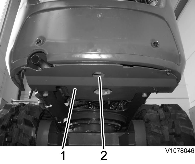
15. Remove closing panel (1).

Figure 10
Closing panel, remove
1. Closing panel
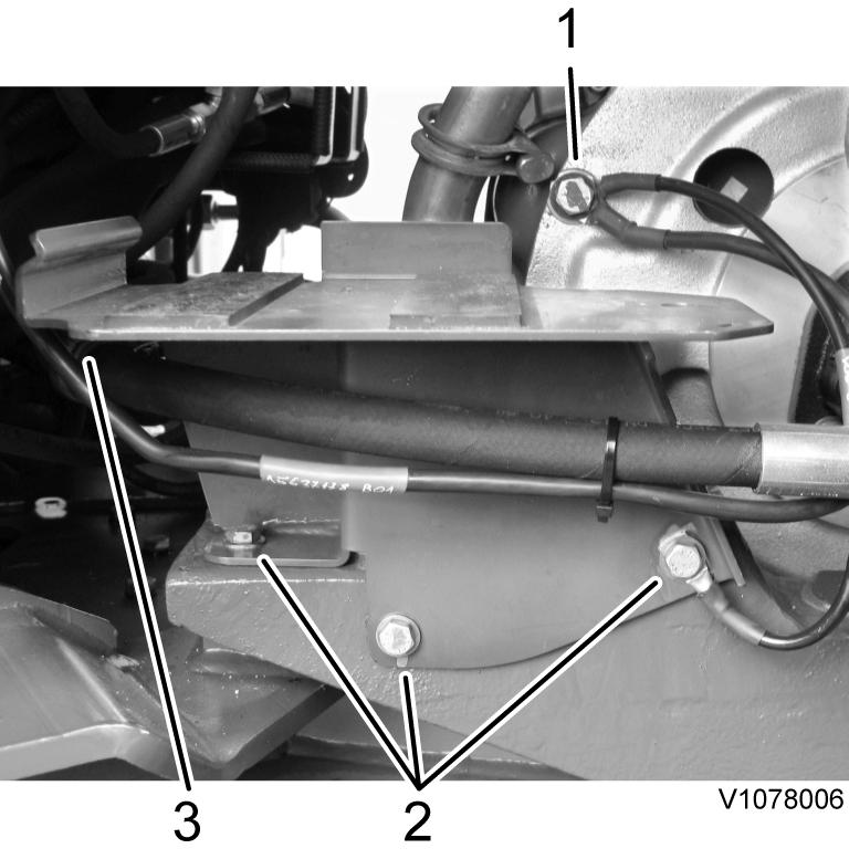
16. Remove cover plate (1)
11 Cover plate, remove
Cover plate Drain plug, fuel tank
17. Remove drain plug (2) and drain fuel tank into a suitable catchment container.
NOTICE
Do the work in an environmentally safe manner.
18. Drain hydraulic tank, see 173 Hydraulic system, changing oil
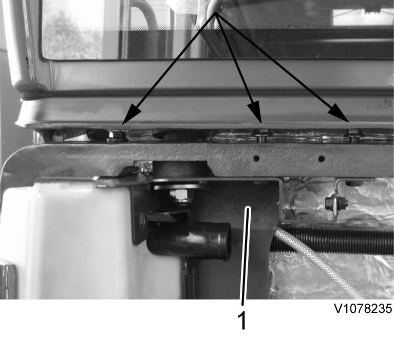
19. Remove nuts (1) from rear cab fixing bolts.

Figure 12 Cab mounting
1. 2. Nuts, cab fixing bolts Connecting bolt cab - cab platform
WARNING
The parts are heavy. Take appropriate safety precautions.
20. Using suitable lifting gear, raise cab at rear eyelets by approx. 3 cm (1.18 in) and secure.

Figure 13 Cab with lifting tool NOTE!
Weight approx. 260 kg (573.2 lbs)
21. Remove radiator, see 261 Radiator, removal
22. Remove alternator, see . 321 Alternator, removing
23. Detach air intake hose (1) at engine.

14 Engine with ancillaries
24. Remove hose clamp (2) from throttle cable.

Figure 15
Hose clamp, remove
1. 2. Mounting screw Hose clamp, throttle cable
25. Detach hose for hydraulic tank ventilation at tank.

Figure 16 Hose line, remove
26. Remove hose clamp (2) and connecting hose (3) with grommet (4).

17
Hydraulic tank ventilation, remove
Hose clamp Screw Jumper hose Grommet
27. Withdraw connecting cable at air filter casing sensor.
28. Remove air filter casing with bracket (1).


31. Remove fixing bolts (1) and remove hydraulic oil filter.
32. Remove fixing bolt (1) for main fuel filter.

21 Main fuel filter, remove
1. 2. Main fuel filter Leak-oil filter
33. Remove fixing bolts and remove leakage oil filter (2).
34. Remove hydraulic hose at leakage oil filter.
NOTICE
When a hose has been disconnected, plug both the hose and the connection immediately. The hoses should be marked for correct connection.
35. Guide leakage oil lines through the opening in the hydraulic oil tank bracket.

Figure 22 Opening, hydraulic oil tank bracket
1. 2. Hose clamp, return line Opening, hydraulic oil tank bracket
36. Release hose clamp (2) and remove suction hose (3) from hydraulic pump.
NOTICE
Collect draining oil.

23
Hydraulic pump, remove
1. 2.
Attaching screws Hose clamp Suction line
37. Remove hydraulic pump
38. Release pipe bracket (1) and connecting clamp (2) and remove exhaust tailpipe (3).

24
Exhaust tailpipe, remove
Pipe bracket Clamp Exhaust tailpipe
39. Release fixing bolts on bracket (1).

Suggest:
If the above button click is invalid.
Please download this document first, and then click the above link to download the complete manual.
Thank you so much for reading
Figure 25 Bracket, remove
1. Bracket
40. Remove upper fixing bolt (2) for left transport bracket (1) on engine, release lower fixing bolt (3) and swivel the bracket forwards.

Figure 26
Transport bracket, swivel
1. 2. 3. Transport bracket
Upper fixing bolt
Lower fixing bolt
41. Remove hydraulic oil tank bracket together with hydraulic oil tank.
42. Swivel the transport bracket into the original position and install bolts (2, 3).
43. Remove bolts (1) for engine mount

Figure 27 Engine mount
1. Screw
44. Remove hose clamp (1) on engine mount.