
Download Manual
Document Title: Function Group: Information Type:Date: Explanations to hydraulic diagram 900 Service Information 11/09/2021
Profile:
EC140B LC Volvo
Explanations to hydraulic diagram
Valid for serial numbers
Showing Selected Profile
Model Production site Serial number start Serial number stop
EC140B LC Volvo
Symbols
Symbol


Reservoirs and accumulators


Filter

Explanation Line
Servo line / Pilot line Line junction
Crossing lines not connecting
Outlet, plugged
Quick-action coupling (e.g. checking point)
Restriction
Restriction, insignificantly viscosity-dependent
Adjustable restriction
Atmospheric (open) reservoir
Accumulator
Filter, strainer

Heat exchanger

Control devices


Sources of energy


Filter with magnetic element
Cooler without representation of lines for the coolant
Manual control by push button
Manual control by lever
Manual control by pedal
Mechanical control by spring, neutral position spring, return spring
Electromagnetic control (one winding)
Hydraulic pressure control
Hydraulic pressure control, two pressure levels
Control via hydraulic pressure drop
Pneumatic control
Control via pneumatic pressure drop
engine
motor
Combustion
Electric
Pumps


Motors


Cylinders

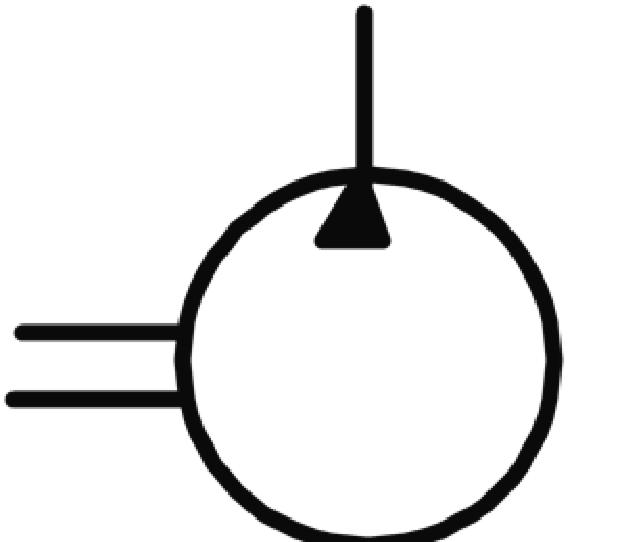
Hydraulic pump with fixed displacement and one direction of flow
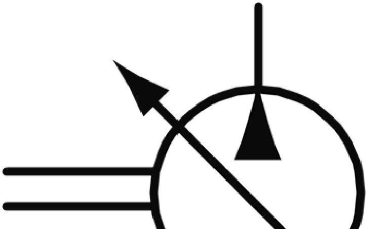
Hydraulic pump with variable displacement and one direction of flow
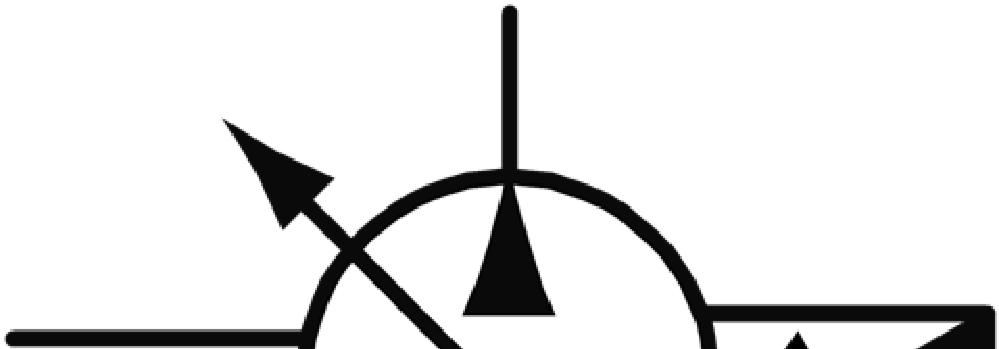
Hydraulic pump with variable displacement and two directions of flow
Hydraulic pump with variable displacement, pressure controlled
Hydraulic pump with variable displacement, pressure controlled with pressure-compensated control
Hydraulic motor with fixed displacement and one direction of flow
Hydraulic motor with fixed displacement and two directions of flow
Single-acting cylinder with return stroke by spring

Valves


Application
Double-acting cylinder with single piston rod (The piston end is called plus side and the piston rod end is called minus side)
Non-return valve which requires very low opening pressure
Non-return valve which requires a certain opening pressure
Shuttle valve
Pressure-limiting valve
Pressure-limiting valve with adjustable opening pressure
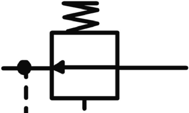
Pressure-reducing valve
Pressure-reducing valve with adjustable closing pressure
Pressure-reducing valve, pressure controlled
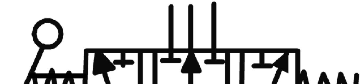
Three-position valve, lever-controlled and spring-centred
Lines parallel with the long sides of the valve symbol show that the valve can take up any position between its end positions (stepless movement)
Shut-off valve / Breather valve
The symbols in a diagram show connections, flow paths and function of the components in the system, but does not show the design of the components.
NOTE!
In a hydraulic diagram the valve symbols are always drawn in neutral position.
Valve symbols
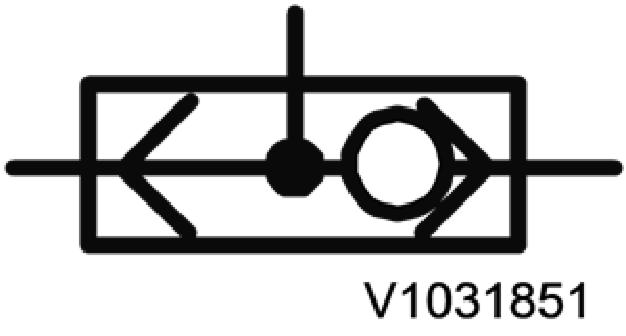
The basic element of a valve symbol is a square box. One box is shown for each position that the moving part of a valve (spool or similar) can take up.
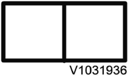
Figure1
Valve symbol
If the valve does not have fixed positions, but can be operated steplessly, this is shown with parallel lines along the valve symbol.

Figure2
Valve symbol, steplessly controlled valve
Internal flow paths and flow directions are drawn in the boxes. Line connections to the valve are drawn to the box that shows the valve position when other components are actuated according to the diagram.
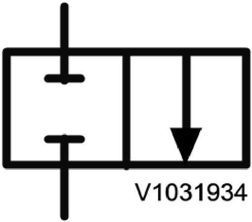
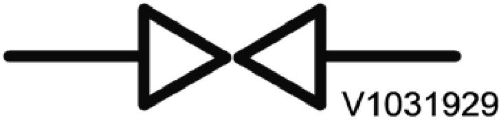
Figure3
Closed valve

Figure4
Open valve
Interpretation of valve symbols
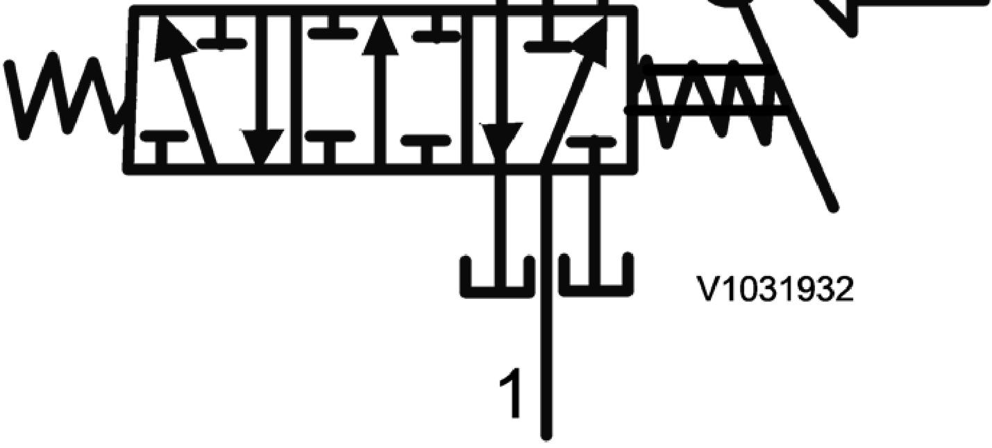
In a three-position valve the spool can be placed in three positions, which in the symbol are represented by one box for each position. The box that represents the intended position is drawn between the line connections, which means that the appropriate connecting paths in the valve are shown in the diagram.
The position in the diagram
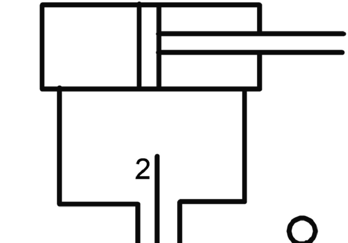

Figure5 Neutral position
Inlet Outlet
The spool is centred in neutral position by the springs. The inlet is connected to the outlet through the spool.
Imagined position for piston movement outwards


The piston rod is pressed out
Inlet Outlet
The spool is actuated with the lever so that the plus side of the cylinder is connected to the inlet at the same time as the minus side is connected to the tank.
Imagined position for piston movement inwards
1. 2.
Figure6
1. 2.
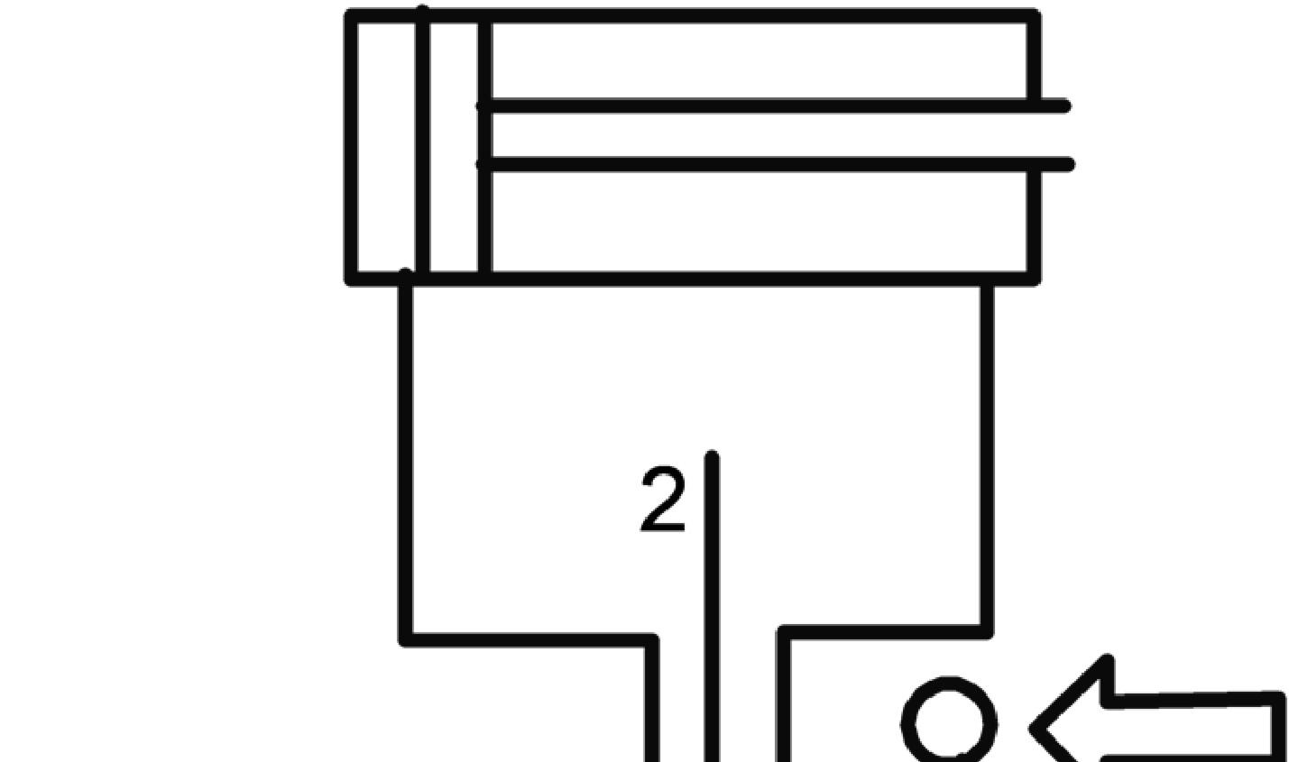
The piston rod is pressed in
The spool is actuated with the lever so that the minus side of the cylinder is connected to the inlet at the same time as the plus side is connected to the tank.
Figure 7
2. Inlet Outlet