

PRODUCTMANUAL DD25
4 Engine
Engine
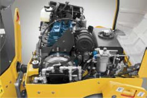
The DD25 is equipped with the new Kubota D1803
25 kW /33 hp, T4 interim / COM 3 a engine Warranty period is currently 1 year/1000 Hours
Customer benefit
• Kubota is among the leaders in maintenance intervals with minimal unplanned downtime and repair costs beyond the warranty period

Engine Fan Guard
Theenginefanhas astandardguardprotectingthefanfromoutsidedebris and preventing the accidental insertion of hands, clothing or tools from contacting the possibly rotating fan blades
Customer benefit
• Decreased risk of damage to the fan during maintenance and more safety to the operator
Operator's environment 5

Visibility
The operator's seating position as well as the shape of the engine hood provideunobstructedvisibilityinalldirections Whetherrolling forwardorin reverse,theoperatorhasaclearviewto therollersedgesandsurroundings
Customer benefit
• Unobstructed visibility reduces operator neck strain
• It also improves job safety with ground crew personnel and the paver operators whilst decreasing possible equipment damage due to bumps and scrapes
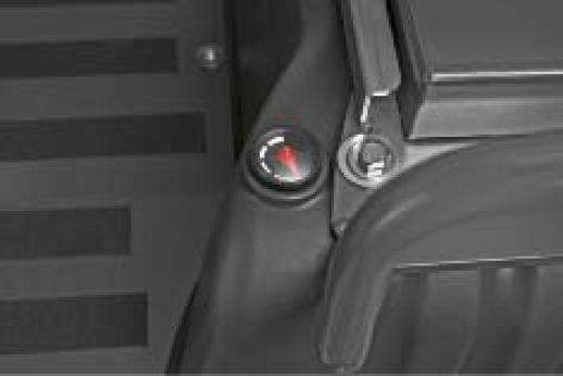
Water Tank Level Indicator
Theoperator can easily monitorwater level,from the operators seat,asthe levelindicatorismounteddirectlyto thewatertank Adialindicatoris used preventing algae build up issues as seen in other water sight gauge designs
Customer benefit
• Water tank level indicator always remains legible allowing water fill scheduling when the water truck or water fill areas are available
• This eliminates downtime due to an empty water tank
6 Operator's environment

Seat Belt Alarm
Anaudiblealarmsoundsshould theoperatorintentionallyorunintentionally unbuckles the seat belt when the brakes are released A warning light on the operator's console illuminates
Customer benefit
• It improves safety by reminding the operator to apply the brakes when leaving the machine or to buckle the seat belt when operating


Thanksto aswitchlocatedintheseatthemachinewillshutdownandapply the brakes should the operator remove himself from the seat.
Customer
• Theseatswitch maintainssafeoperatingconditions shouldtheoperator come off of the seat for any reason.
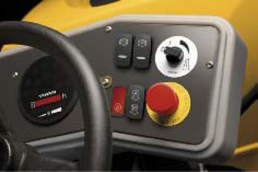
A vandal cover is provided to cover the operators control panel
Customer benefit
• Vandalcoversecuresthecontrolareafromvandalismwhenthemachine is parked in unsecure work sites.
Operator's environment 7

Rubber Operator Platform Isolators
Theoperatorplatform is isolatedfromthemainframeby4 rubber isolators designed to effectively absorb vibration feedback through the machine to the operator
Customer benefit
• Greatly increases operator comfort decreasing fatigue
• Improves operator performance, productivity and safety.

Adjustable Operators Seat
Fully adjustable operators seat can be adjusted for the amount of seat spring and forward/rearward positions.
Customer benefit
• Operators of any weight and size can adjust the seat to the most comfortable and productive working position.

Retracting Seat Belt
Retractable 3 inch seat belt as standard for safety and longevity
Customer benefit
• Theretractingseatbelt canbeperfectlyadjustto thedifferentsizes,also it retracts automatically when not used by the operator protecting it from dirt, damage and a tripping hazard
8 Operator's environment

All units are equipped with a horn as standard The horn switch is located on the left side of the operators console Customer benefit
• The horn is within the operators reach ready to quickly alert personnel and other equipment of the machines presence

Eccentric frequencies
Volvo pioneered high frequency with the industry's first 66 7 Hz (4000 VPM) compactor in 1975 Higher frequencies enable the operator to travel faster while maintaining proper impact spacing
Customer benefit
• This ability to increase travel speeds increases total machine productivity
• Maintainingtheproperimpactspacingprovidesasmootherqualityfinish on the asphalt surface

Drums Surfaces and Edges
DD25 drums are machined on an industrial lathe to make them perfectly round In addition, each drum edge receives a special profile treatment to help reduce pavement marking There is a chamfer (bevel) of the outer 20 millimeters of the drum surface There is also a 9 millimeters radius additionally machined at the edge for rounding.
Customer benefit
• Machined drums and chamfered edges contribute to a smooth rolling finish without marking the asphalt.
• This reduces the number of passes needed for a final quality finish.

The operator can easily change eccentric frequencies from 3300 vpm / 55 Hz to 4000 vpm / 67 Hz to match performance to production requirements by repositioning the engines throttle lever
Customer benefit
• Numerous application conditions from site maneuverability, mixdesign and asphalt temperatures could likely cause conditions for frequency adjustments needed for improvements in smoothness and density
10 Drums

Available for DD25 (010) () (2)
Available for DD25 (017) () (2)

Available for DD25 (008) () (2)
Maintenance free Bearings
Eccentricbearingsarelubricatedwithlithiumgrease(abletotoleratehigher temperatures and rotating speed) and sealed The system is maintenancefree
Customer benefit
• Decreases maintenance costs and down time
• Environmentally friendly due to less waste by eliminating oil changes.
Theautomaticvibrationfunctionensuresthatthevibrationwillautomatically turn off prior to stopping on the asphalt.
Customer benefit
• The automatic function eliminates the possibility of the operator forgetting to turn the vibration off damaging the asphalt surface.
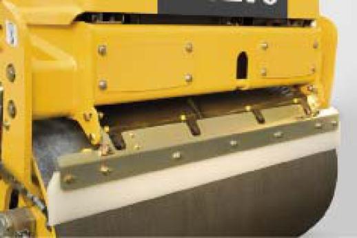
Urethane Drum Wipers
Frontandreardrumfeaturewipersmadeofurethaneasstandard Urethane hashighercut and tearresistance thanrubberthatis usuallyused fordrum wipers
Customer benefit
• Effective drum wiping on a longer period of time, even on especially abrasive applications
• Operating and maintenance costs are reduced as well as waste products
Drum Wipers Spring Tensioners
When the wiper contact is lost, added water flow and possible asphalt damage will result causing rework and increase need for water refills
Constant spring tension adjustment ensures automatic and consistent contact of the wiper to the drum surface
Customer benefit
• Eliminates maintenance needed to maintain the contact to the drum
12 Water system
Pressurized Water System
Front and rear drums are covered by a pressurized water system that provides a consistent flow of water to the drum surfaces Water flow is maintained by a specially designed diaphragm pump and primary water filter Fine filters behind each of the 4 spray nozzlesminimizeclogging and help to ensure proper fan spray coverage to the drum surfaces. The entire system is rust-proof
Customer benefit
• Eliminates the possibilities of asphalt material pick-up.
• Thisreducespossibledamageto theasphaltsurfacedecreasingrework while increasing productivity
Adjustable Water Intermittent
The operator can precisely adjust water flow for adequate drum coverage to keeptheasphaltformstickingto thedrum Thewaterflowswitch adjusts the time between spray activation Minimal requirements will save in the usageofwaterandtheneedforawaterrefill Theflowadjustmentscontrols flow to both drums
Customer benefit
• Improves eliminating asphalt pick up and decreases down time waiting for a water truck
Service and maintenance
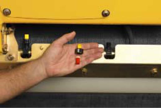
Water Nozzles and Screens
The brass fan-spray nozzles and screens are designed for quick removal without the use of tools, should the nozzle become restricted
Customer benefit
• Water nozzles can be changed very quickly without the need for tools increasing uptime and water system performance

Daily Checkpoints
This machine was designed with maintenance requirements in mind Each daily checkpoint is positioned so it is easily located and accessible from ground level
Customer benefit
• Easy access to all maintenance areas decrease maintenance time and improves quality of daily inspections
Remote Hydraulic and Engine Oil Drains
Grouped remote hydraulic and engine oil drain hoses are secured to the machine frame located behind an access cover on the left side of the front main frame
Customer benefit
• Oil change is quickly and cleanly performed
14 Service and maintenance

Service Chart with Detailed Check Points
Theeasytounderstandmaintenanceservicechartislocated ontheengine hood for easy reference
Thisinformationprovidesmaintenanceintervalandlubricationrequirements for the operator and maintenance personnel
Customer benefit
• Ensures proper lubrication and maintenance procedures are followed for increased life of the machine

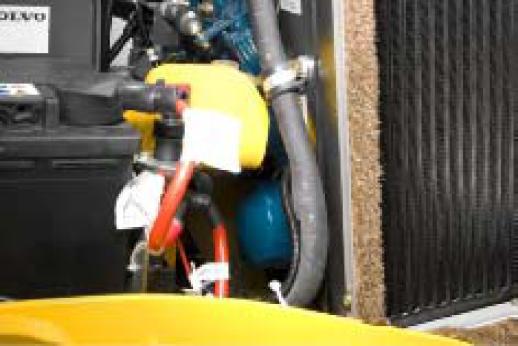
Battery
Disconnect Switch
The battery disconnect is located in the engine compartment, providing protection to the electrical system.
Customer benefit
• Provides asafe environment when working on the electrical system and decreases the chance of theft.

Battery
The battery is a heavy-duty maintenance free 12 volt / 800 CCA sealed battery. This AGM, Absorption Glass Mat, battery resists damage from vibration and shock, offers excellent starting characteristics and holds a charge longer during storage
Customer benefit
• Reliable battery
• Protects the operator from possible acid leaks
Service and maintenance
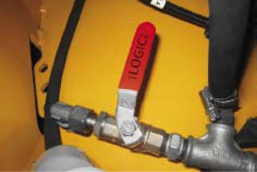
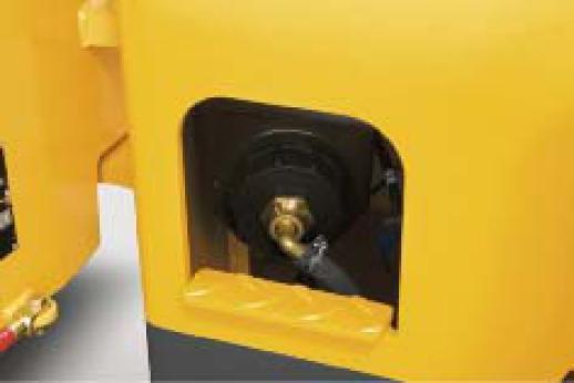
Water Drain Valve
Water drain valve is located behind the left side access panel on the rear mainframeandiseasilyaccessed whenquick waterdrainingisneededfor freezing weather conditions and maintenance
Customer benefit
• Decreases maintenance costs and damages caused in freezing climates


Engine Hood Opening
The hinged engine hood design is light weight It tilts forward with the support of 2 gas cylinders to give wide access to the engine and hydraulic components
Customer benefit
• Effortless opening of the engine hood for daily inspection.
Fuel Cap
The lockable fuel tank fill cap is located on the right side of the machine
Customer benefit
• The fuel fill is easily accessed from the ground
• Fuel is protected from theft, vandalism and contamination
16 Service and maintenance

for DD25 (028)
Hydraulic Quick Connect Test Ports
Quick connect test ports are installed on easy to access locations on the propulsion pump
Customer benefit
• Improving troubleshooting time and decreases the risk of contaminants from entering the hydraulic system.
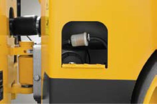
for DD25 (031)
Thepre filter effectively removes anyparticles from the fuel prior to the fuel filter.
Customer benefit
• The filter is easily accessed next to the water tank strainer inlet area.
• Prevents damage to injection pump and injection nozzles.
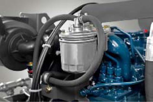
for DD25
Fuel primer screw is mounted directly to the head of the main fuel filter on the side of the engine
Customer benefit
• In the event of running out of fuel and during fuel system maintenance a fuel primer pump is mounted directly to the fuel filter head
• This standard feature decreases down time should the fuel system develop air in the system
Service and maintenance

Fuel Filter
After the pre filter, the fuel passes another fuel filter
Customer benefit
• Protects the injection system from contaminated fuel and reduces the risk of malfunction
Engine Filtration
The engine oil is filtered through a full flow filter located on the side of the engine. The filter is a spin on type and is easily replaced.
Customer benefit
• Engine Spin on type oil filter is easily accessed in the engine compartment from ground level
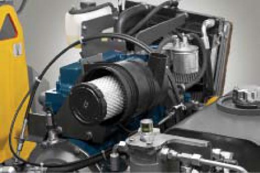
The first stage filter element has long replacement intervals depending on conditions A second stage safety element is present to capture particles that may get past the first stage filter
Customer benefit
• The 2 stage engine air filter is easily located and maintained under the engine hood in the engine compartment
• Dependable heavy clip fasteners gives access to the filter elements withouttheuseoftoolswhileproperlysecuringthehousingsealingarea
• Thefilterelements protect the engine and increases operating life of the machine
18 Service and maintenance

Air Filter Restriction
Air filter restriction indicator is mounted directly to the air cleaner for easy access and for operator monitoring of the air cleaner elements condition This eliminates the need for air cleaner inspection by opening the filter housing
Customer benefit
• The air filter restriction indicator gives the operator the indication of the air cleaner element condition as a dirty element reduces engine performance.
• The operator also can decide when service is needed eliminating the need for opening the air filter assembly increasing the possibility of ingesting dirt directly into the engines air intake
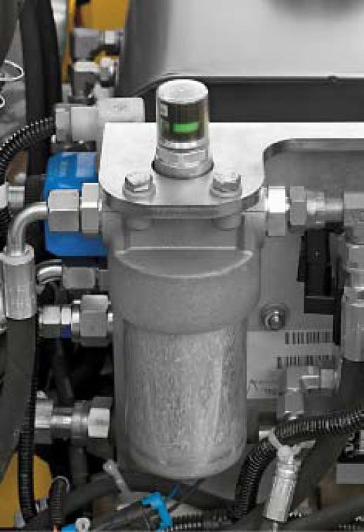
Hydraulic Filter Restriction Indicator
Hydraulic filter restriction indicator mounted directly to the filter head for visual inspection between filter changes
Customer benefit
• Restriction Indicator allows the operator and maintenance personnel to monitor filter efficiency between filter change requirements
Service and maintenance 19
Quick Disconnect Water Hose
The drum suction filter hose connection uses a hand tightening fitting for easy removal to access the suction strainer
Customer benefit
• The drum water system suction strainer can be easily access for cleaning, depending on the cleanliness of the water used, may need to be removed numerous times
• A quick spin on and off suction hose fitting is used to eliminate the use of tools for removal.

Water Tank Inlet
Water tank inlet and cap located on the left rear corner of the tank accessible from the ground for easy access
Customer benefit
• Water fill inlet accessible for the ground large enough for various sized fill hoses

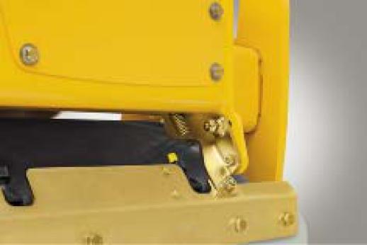
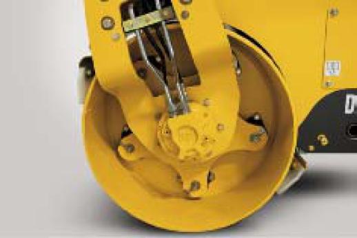
Center Joint Lock
Thecenterjointarticulationlockbarmanuallylocksthejointintopositionnot allowing any unforeseen movement in either direction
Customer benefit
• The center joint locking bar should be locked during service and transportation
• The locked center joint increases safety for service personnel when entering the center joint articulation area
20 Frame
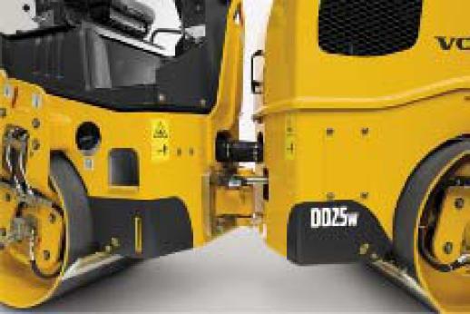
Articulation/Oscillation Joint
Center Jointgives 30 degrees of articulation and 10 degrees of oscillation for machine performance It provides uniform compaction as the trailing drum follows the path of the leading drum
Customer benefit
• Decreases the number of passes needed to obtain full rolling coverage
• Provides excellent driver comfort and stability

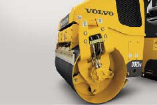
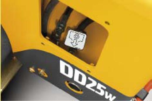
Central Lifting Device
A heavy duty lifting eye is mounted to the frame for ease of shipping or transporting
Customer benefit
• Easeof properliftingwhenshippingortransportingdecreasesimproper lifting methods used which maycause machine damage or personal injury
Towing Equipment
Equipment needed to tow the machine are designed into the components A simple valve adjustment located on the propulsion pump and brake release hardware located on both the front and rear drum drive motors The tow feature can be activated with the use of general mechanics tools.
Customer benefit
• In the event of a machine break down during operation, the compactor can quickly be removed to avoid damage of the asphalt.

Electrical system
Electricalsystemisfullyprotectedandallelectricalconnectionsaresealed, waterproof and meet the standard safety rules
Customer benefit
• All electrical components are of sturdy design to provide reliability
• Each individual wire, connector and pins are clearly and systematically colored and/or number coded for quick troubleshooting and repair

Brake Test
The brake test procedure allows the operator to test the brake function through the brake test circuit to ensure the brake system is performing properly
Customer benefit
• The test method of the brake system reduces risk for machine damage with high level of safety
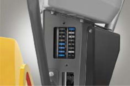
Fuses
Keyfuses are located in the left hand side of the console pedestal for easy access
Customer benefit
• Fuses can be easily inspected and changed quickly by removing the access cover on the left hand side of the operators console pedestal protected from the elements
• A fuse decal is placed on the cover for fuse identification
22 Electrical
Available for
(040)

Available for

Starter Motor Protection
Starter motor is protected from damage of the driving pinion Theignitions key can't go to the start position if the engine is running
Customer benefit
• Starter protection eliminates the chance of damage decreasing costly repairs and longer life of the starter.
Relays
Electrical system relays are grouped and mounted in the console for easy access for troubleshooting. All relayshaveidentification tags for reference to the electrical schematics
Customer benefit
• Grouped and identified relays decreases the troubleshooting time
Switches
Operators console switches are sealed for weather protection.
Customer benefit
• Switches are protected from moisture, corrosion and dust
• It limits the risk of malfunction or breakdown for low operating costs
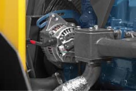
Alternator
A large 45 Amp alternator is standard providing sufficient power if the machine is fitted with additional options, lighting for example.
Customer benefit
• The large 45 amp capacity alternator enables additional electrical equipment such as lighting installations
24 Hydraulics
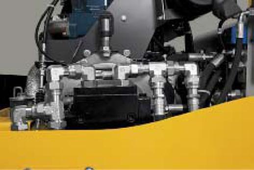
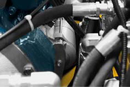
Hydraulic Connectors
All hydraulic fittings haveORS connection sealing TheORS technology is used onmost hydraulicconnectors to ensurea100% leakproof system It provides an excellent resistance to pressure peaks, vibration and twisting
Customer benefit
• The hydraulic system is effectively sealed from leakage and external contamination

Pump Return to Neutral
Thepumpreturntoneutralsystemwillnotallowthemachinetopropelwhen the brakes are in the applied condition
Customer benefit
• Whentheoperatorapplies thebrakesthemachinespropulsioncircuit is disable not allowing him or her to propel against the brake system increasing the life of the brake discs improving long life brake performance
Index alpha
volvoconstructionequipment
FOR INTERNAL USE ONLY
