Parts Manual
972L Wheel Loader
RFB1-UP (Machine)
WYE1-UP (Engine)
NA71-UP (Transmission)
NA81-UP (Transmission)
FJ41-UP (Torque Converter)
HY81-UP (Torque Converter)
TXS1-UP (Torque Converter)
ZWJ1-UP (Torque Converter)
TABLE OF CONTENTS
TABLE OF CONTENTS
TABLE OF CONTENTS
TABLE OF CONTENTS
TABLE OF CONTENTS
COUPLER GP-QUICK 1962
EDGE GP-CUTTING 1970
EDGE GP-SEGMENT 1971
EDGE-END 1972
EDGE-SEGMENT.....................................................1973
FORK GP-PALLET..................................................
GUARD GP-BUCKET CORNER..........................
PLATE AS-WEAR...................................................
PLATE GP-WEAR
PLATE-WEAR
PROTECTOR
PROTECTOR GP-LINKAGE
TIP AS-ABRASION
TIP AS-GENERAL PURPOSE .............................1994
TIP AS-PENETRATION .........................................1995
TIP GP-ABRASION.................................................1996
TIP GP-EXTRA-DUTY 1998
1.
MACHINE IDENTIFICATION
GENERAL INFORMATION
Components such as engines, transmissions, axles, etc.
Cat machines are identified by Product Identification and work tools will continue to use an 8 character Serial Numbers (PIN). Some components included in a Number (S/N). machine may be identified by Serial Numbers (S/N).
Typical components that will be serialized include engines, transmissions, bulldozers, and rippers. The machine and engine are further identified by arrangement numbers and in some cases modification numbers. These numbers are shown on the product identification plate(s) and on the master plate in the operator's compartment.
Cat dealers need all of these numbers to determine accurate parts identification.
2.ORDERING PARTS
Effective First Quarter 2001 the Cat Product Identification Number (PIN) changed from 8 to 17 characters. In an effort to provide uniform equipment identification, Caterpillar and other construction Quality Cat replacement parts are available from Cat equipment manufacturers are moving to comply with the dealers throughout the world. Their parts inventories are latest version of the product identification numbering up to date and include all parts normally required to standard. Non-road machine PINs are defined by ISO protect your investment in Cat machines. Dealers may 10261. The new PIN format will apply to all Cat offer repair kits or remanufactured parts to allow machines and generator sets. The PIN plates and frame selection of the most effective repair alternative for a marking will display the 17 character PIN. The new particular situation. When ordering parts, your order format will look like the following: should specify the quantity, part number, part name, and the serial number/product identification number of the machine for which the parts are needed.

Where:
3.PARTSMANUALORGANIZATION
Product information in this manual is presented as "information elements" that represent all of the components for the specific model. Engine Arrangement and Seat Group are examples of information elements. The information elements are organized alphabetically by part name and secondarily by part number within each major section of the manual.
4. TABLEOF CONTENTS
1. Caterpillar's World Manufacturing Code (characters 1- A table of contents (TOC) is found at the beginning of the 3) manual. The TOC lists each section of the manual with a
2. Machine Descriptor (characters 4-8) complete list of all information elements organized as they appear in the manual. Page numbers are provided
3. Check Character (character 9) for quick reference to detailed parts identification illustrations and serviceable consist lists.
4. Machine Indicator Section (MIS) or Product Sequence Number (characters 10-17). These were previously
5.MAINTENANCEPARTSINDEX referred to as the Serial Number.
Machines and generator sets produced before First
The Maintenance Parts Index, located near the Quarter 2001 will maintain their 8 character PIN format. beginning of the manual, references most frequently used maintenance part numbers, providing description, quantity, usage and page number. This information is organized alphabetically by part description.
6. INDEX
GENERAL INFORMATION
12. ILLUSTRATION REFERENCE LETTERS
The index located near the front of the manual is an When necessary, illustrations contain reference letters alphabetical listing of all information elements included in (A, B, C etc.) that are intended to track lines and the manual. Page numbers are provided for quick harnesses from one point to another. They are also used reference to detailed parts identification illustrations and to show where to reconnect illustrations that have been serviceable consist lists. separated.
7. PARTNUMBERINDEX
13.ABBREVIATIONSANDSYMBOLS
A numerical index listing all part numbers and the O.D. – OutsideDiameter corresponding page number(s) appears at the back of I.D. – Inside Diameter the manual. A – Not Part Of This Group B – Use As Required
8. CAPTIONS C – ChangeFrom Previous Type D – Order By The Meter
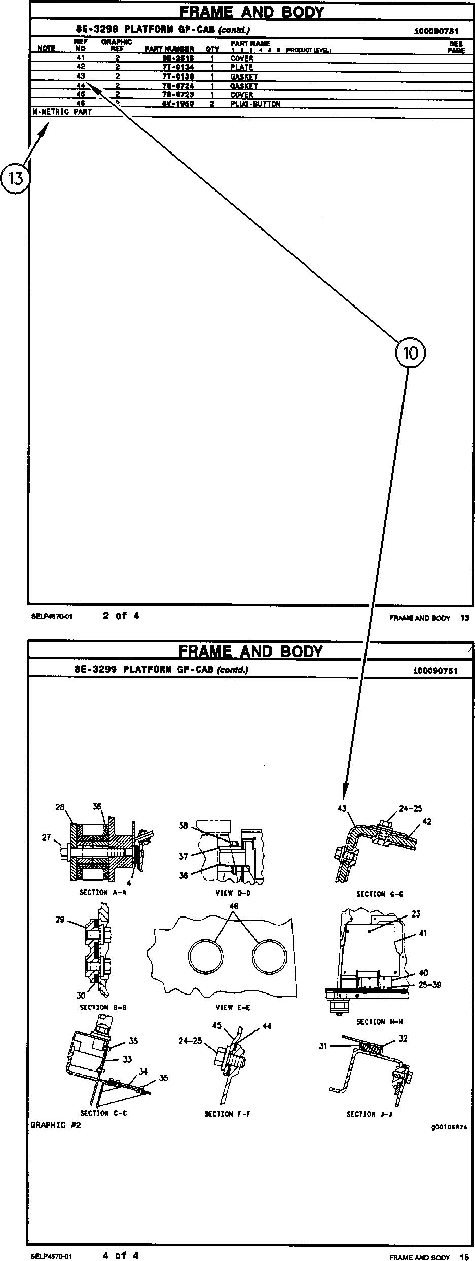
Captions located at the beginning of each information E – Order ByTheCentimeter element identify the part number and part name along F – Not Shown with additional descriptive information. PIN and S/N G – Order By The Inch information found in each caption should be used to I – ReferToHydraulicInformationSystem select correct information for a specific machine. Field M – Metric Part replacement options, identification of optional R – RemfgPartMayBeAvailable attachment components, and where used ("part of") Y – Separate Illustration information is also provided. Z – Not Serviced Separately
The first line of a caption is shown in larger type font to
14. DESCRIPTION OF TYPE CHANGES indicate the beginning of an information element. Captions for additional pages that may be required to Type - A type is defined as any configuration change that illustrate an information element will be shown in requires an additional Information Element for an standard type font and will include the term (contd.). Arrangement, Group, or Assembly. If serial number breaks for types are not available, a type # ( Type 1, 9. NON-SERVICED PARTS
Type 2, etc.) will be displayed in the caption. These
In some instances it is necessary to display non-serviced "type" changes are identified with a "C" note (change
parts that are a link to a lower level serviceable consist from previous type) in the Parts List. Only the "types" that lists. These non-serviced part numbers are shown in apply to this Parts Manual will be included. Additional italic type indicating that they are not available. types may exist causing "C" notes to appear on an Information Element when no other types areshown.
10. PARTS LIST REFERENCE NUMBERS
15.<END>
Numbers shown in the Ref No column correspond to This symbol indicates the end of an information element. numbers used in the associated graphic(s). An alphabetic suffix may be added to a reference number to
NOTE: identify lower level consist items. Numbers shown in the Graphic Ref column refer to the graphic number identifier Continuing improvement and advancement of product displayed in the lower left corner of each illustration. The design may cause changes to your machine which may Graphic Ref number may be used in combination with not be included in this publication. Whenever a question the item Ref No to determine the correct part number. arises regarding your Cat product or this publication, There may be intentional omission of a Ref No in a please consult your Cat dealer for the latest available consist list as information is updated to reflect the latest information. serviceable part numbers.
11. INDENTED PART NAMES
When a part name is indented in a parts list, it is part of (included in) the group or assembly under which it is indented.

REPAIR ALTERNATIVES
REMANUFACTURED COMPONENTS
As an optionwhen making repairs consider Cat Remanufactured Components. Components that areavailable through the Cat Remanufactured Program are identified three ways in the parts book:
• with the letter R in the note field of the parts list
• with an R* at the beginning of the first line of the caption
• with an *R at the end of the first line of the caption
TypicalcomponentsincludedintheRemanufacturing Programinclude:
ALTERNATORS
CONNECTING RODS
CRANKSHAFTS - UNDERSIZE
CRANKSHAFTS-UPGRADETONEW
CYLINDER HEADS
ELECTRONICCONTROL MODULES(ECM)
ELECTRONIC SENSORS
FUELINJECTORS
FUEL NOZZLES
FUEL PUMPS
GOVERNORS
OIL PUMPS
PISTONS
SHORTBLOCKS
STARTERS
TURBOCHARGERS - COMPLETE
TURBOCHARGER CARTRIDGES
WATER PUMPS
CatRemanufactured engines formany enginearrangements arealsoavailable.
SUPPLEMENTAL COOLANT ADDITIVES
CUSTOMER BENEFITS:
Protects againstcavitation, foam, erosion,corrosion,andscale buildup incoolingsystems.
• Providesmeasuredcoolant conditioner.
DESCRIPTION:
Additives depletefrom thecoolant with normal operation.For this reason, Supplemental Coolant Additives (SCA) must be added to all heavy duty coolants at regular intervals. In addition, when not using a fully formulated, pre-charged antifreeze, like Cat DEAC, an initial charge of SCA must be added to the cooling system. The amount of SCA added to the system is dependent on the capacity of the system.
The SCA for initial fill is provided as a liquid. SCA's for maintenance intervals are available in liquid form and as a spinon element. (No Spin-on available for 3600 Family of Engines)
NOTE:
The amount of SCA added at initial fill is not the same as the amount added at maintenance intervals.
Thecoolant additive elements can be usedwith any ethylene or propylene glycol type antifreeze which meets ASTM D4985 or ASTM D5345 Specifications.
NOTE:
For use with standard heavy duty coolant only, not for use with Extended Life Coolant.
PARTSNEEDED:
(6-8)
(8-10)
(1)
(1) 6V-3542 (1)
(10-13) 3P-2044 (1) 8T-1589 (1)
(1)
(1)
(1)
(1) 49-64 (13-17) 3P-2044 (2)
(1)
(1) 64-83 (17-22)
3P-2044 (2) 8T-1589 (1)
83-114 (22-30)
(1) 6V-3542 (1)
3P-2044 (3) 8T-1589 (1) 3P-2044 (1)
(1)
(1) 114-163 (30-43) 3P-2044 (5) 3P-2044 (1) 6V-3542 (1)
(2) 163-242 (43-64) 3P-2044 (8)
3P-2044 (2) 9N-3718 (2)
*Normal maintenanceperiod is 250 hrs. See your Operation and MaintenanceManual for complete coolant maintenance instructions.
( ) Indicates quantity required.
MANUAL RESET)
(TRANSMISSION ECM)
(MAIN)
AUTOMATIC RESET) (AUTOMATIC RESET)
MANUAL RESET)
(STARTER)
MAINTENANCE PARTS
SYSTEM
MAINTENANCE PARTS
MAINTENANCE PARTS
MAINTENANCE PARTS
ACCUMULATOR GP-BRAKE–CHARGED 1156 1157
ACCUMULATOR GP-BRAKE–UNCHARGED 1158
ACCUMULATOR GP-HYDRAULIC–CHARGED ................................................................1161 1218
ACCUMULATOR
ACCUMULATOR
ACCUMULATOR GP-RIDE CONTROL–CHARGED
ACCUMULATOR GP-RIDE CONTROL–UNCHARGED 1219
ACTUATOR GP-POWER 811 ACTUATOR GP-POWER (POWER TRAIN GUARD) 811 ADAPTER
AXLE
AXLE
AXLE
BLADE AS-WIPER (800-MM) (FRONT WINDOW)
CAB AR-ENCLOSED ROPS
CAB AR-ENCLOSED ROPS–STEEL MILL
GP (115-DEG, COLOR)
CAMSHAFT GP
CAP AS-FILLER (7/8-9-THD)
CAP AS-FILLER (LOCKABLE) (HYDRAULIC TANK)
CAP AS-FILLER (M18X2-THD)
CAP AS-FUEL (LOCKABLE, VENTED)
CAP AS-VENTED. 1877
CAP GP-AIR CLEANER
CAP GP-FUEL FILLER................................................
CAP GP-PROTECTION–CORROSION
CAP-FILLER (BRAKE, DIFFERENTIAL, XMSN OIL)
CAP-VENTED (VENTED).........................................
CARRIAGE GP-FORK...............................................
CARRIAGE GP-FORK–HOOK-ON
CARTRIDGE GP-TURBOCHARGER
CIRCUIT
WINDOW)
(ALTERNATE EXIT, REMOVE OMM)
(FLYING DEBRIS, READ
FILM-WARNING (ROPS, FOPS, READ OMM) 2007
FILM-WARNING (ROTATING FAN) 2018
FILM-WARNING (SEAT BELT, INTERNATIONAL)....................................................2021
FILM-WARNING (SEAT BELT) 2005
FILM-WARNING (UNIVERSAL, READ OMM). 2005
(ETHER START).
(LUBRICATION PUMP)
FILTER AS-AIR (STANDARD FILTRATION) (PRECLEANER) 1820
AS-ENGINE OIL...............................................84
AS-WATER SEP & FUEL (ULTRA HIGH EFFICIENCY)..............................................................
ELEMENT-AIR (HIGH DEBRIS) .................
ELEMENT-AIR (ULTRA HIGH EFFICIENCY)..............................................................
ELEMENT-BREATHER (HYDRAULIC TANK) 1440 FILTER ELEMENT-CAB AIR.....................................1722 1723 FILTER ELEMENT-CAB AIR (STANDARD FILTRATION)............................................................1722 1723 FILTER ELEMENT-FUEL 186
ELEMENT-OIL...............................................
GP-ENGINE OIL
GAUGE GP-SIGHT (OIL LEVEL) 644 647
GAUGE GP-SIGHT (OIL LEVEL) (POWER TRAIN OIL) 634 636 638 640 642
GAUGE-LIQUID LEVEL (SIGHT GLASS) (HYDRAULIC TANK OIL) 1438
GEAR GP-BEVEL & PINION.....................................670 672 674 676
GEAR GP-FRONT 49
GEAR GP-OUTPUT TRANSFER 678
GRILL GP-RADIATOR .................................................905 907
GUARD AR-HEAVY DUTY.........................................908 909
GUARD AR-LIGHT. 909
GUARD GP-AXLE 910
GUARD GP-BELT...........................................................50
GUARD GP-BOTTOM..................................................911 912
GUARD GP-BUCKET CORNER. 1980
GUARD GP-FAN 110
GUARD GP-FRONT 913
GUARD GP-HITCH & STEERING............................914
GUARD GP-LIFT CYLINDER.................................. 1249
GUARD GP-LIGHTING 915 916 917 918
GUARD GP-LINES. ......................................................919
GUARD GP-LOADER
LINES GP-TORQUE CONV COOLER 750 752 754
LINES GP-TURBOCHARGER OIL. 93
LINES GP-WATER–RADIATOR.................................130
LINK GP-STEERING FRAME LOCK......................1051
LINK GP-TILT 1634 1635 1637 1639
LINKAGE AR-BUCKET...............................................1639 1640
LITERATURE GP (STANDARD CAB) 5
LUBRICATION AR-AUTOMATIC 1052 1053 1054
LUBRICATION AR-AUTOMATIC–AUTOLUBE.......1052
LUBRICATION AR-AUTOMATIC–HIGH LIFT 1052 1054
MANIFOLD
MANIFOLD GP-CONTROL–AXLE OIL FLOW DIVIDER................................................................... 1209
MANIFOLD
MANIFOLD GP-HYDRAULIC 1410 1411 1413
MANIFOLD GP-INLET..................................................172
MIRROR GP ............................................................... 1755
MIRROR GP-REAR VIEW 1756 1758
MIRROR GP-REAR
PROTECTION GP-WIRING
PROTECTOR GP-EDGE
PROTECTOR GP-LINKAGE .....................................
PULLEY GP-CRANKSHAFT .........................................
PUMP & MTG GP-BRAKE & HYD FAN 1417
PUMP & MTG GP-HYDRAULIC 1418 1419 1420
PUMP & MTG GP-HYDRAULIC FAN....................1421
PUMP & MTG GP-LUBRICATION..........................1087
PUMP & MTG GP-LUBRICATION–AUTOLUBE 1088
PUMP & MTG GP-SECONDARY STEER 1576
PUMP GP-ELECTRIC DRIVE 1577
PUMP GP-ENGINE OIL.................................................
PUMP
(2-PIN) (FRONT
(2-PIN) (REAR
SENSOR GP-POSITION (STEERING)
SENSOR
(3-PIN) (ENGINE
INDEX
SWITCH AS-PUSH BUTTON (LUBRICATION PUMP) .......................................................................1090
SWITCH AS-PUSH BUTTON (PAYLOAD STORE). 416
SWITCH AS-PUSH BUTTON (THROTTLE LOCK ON, OFF) 515
SWITCH AS-ROCKER (24-VOLT) 431 436 443
SWITCH AS-ROCKER (24-VOLT) (AIR CONDITIONER CONTROL) 450
SWITCH AS-ROCKER (24-VOLT) (AIR CONDITIONER ON, OFF)......................................457
SWITCH AS-ROCKER (24-VOLT) (AIR CONDITIONER, HEATER)......................................442
SWITCH AS-ROCKER (24-VOLT) (HAZARD LIGHT).........................................................................419
SWITCH AS-ROCKER (24-VOLT) (HYDRAULIC LOCKOUT)..................................................................513 515
SWITCH AS-ROCKER (24-VOLT) (IMPLEMENT LOCKOUT) 503 505 509 511
SWITCH AS-ROCKER (24-VOLT) (QUICK COUPLER) 418
SWITCH AS-ROCKER (24-VOLT) (WINDOW WASHER) 449 457
SWITCH AS-ROCKER (AIR CONDITIONER, HEATER).....................................................................435
SWITCH AS-ROCKER (FORWARD, NEUTRAL, REVERSE) 433 1661 1663 1669 1671 1677
SWITCH AS-ROCKER (HEATED MIRRORS)..... 1757
SWITCH AS-ROCKER (PARKING BRAKE) 433
SWITCH AS-ROCKER (POWER) 433
SWITCH AS-THERMOSTAT (HVAC) 1645
SWITCH AS-TOGGLE (BOTTOM GUARD) 426
SWITCH AS-TOGGLE (HOOD TILT ACTUATOR)...............................................................
SWITCH AS-TURN SIGNAL
SWITCH GP-DISCONNECT
SWITCH GP-MAGNETIC (24-VOLT) (START RELAY)
VALVE & LINES GP 1441
VALVE & LINES GP-LUBRICATION........................1128 1129 1132 1137
VALVE & LINES GP-LUBRICATION–FRONT 1126 1135
VALVE & LINES GP-LUBRICATION–REAR 1125
VALVE & LINES GP–REAR......................................1447
VALVE & LINES GP–WITH HEAT INSULATION 1443 1445
VALVE & MTG GP-CONTROL–2-VALVE 1449 1454
VALVE & MTG GP-CONTROL–2-VALVE, RIDE CONTROL.................................................................1456
VALVE & MTG GP-CONTROL–3-VALVE 1459
VALVE & MTG GP-CONTROL–WITH RIDE CONTROL 1451
VALVE & MTG GP-COUPLER................................1462
VALVE & MTG GP-MAIN CONTROL–3VALVE 1464
VALVE & MTG GP-RIDE CONTROL 1468
VALVE AS-PRESSURE RELIEF (REFRIGERANT COMPRESSOR) 1659
VALVE AS-RELIEF 218
VALVE AS-RELIEF (LUBRICATION)........................1091 1097
VALVE GP 1474
VALVE GP-ACCUMULATOR CHARGING 1161 1162
VALVE GP-ACCUMULATOR CHARGING (BRAKE)....................................................................1156 VALVE GP-CHECK
VALVE GP-CHECK (AUTOMATIC LUBRICATION LINE)............................................................................988
VALVE GP-CHECK (AXLE OIL COOLER BYPASS)...................................................................
VALVE GP-CHECK (PARKING BRAKE