2 minute read
Service and Repairs


Radiator
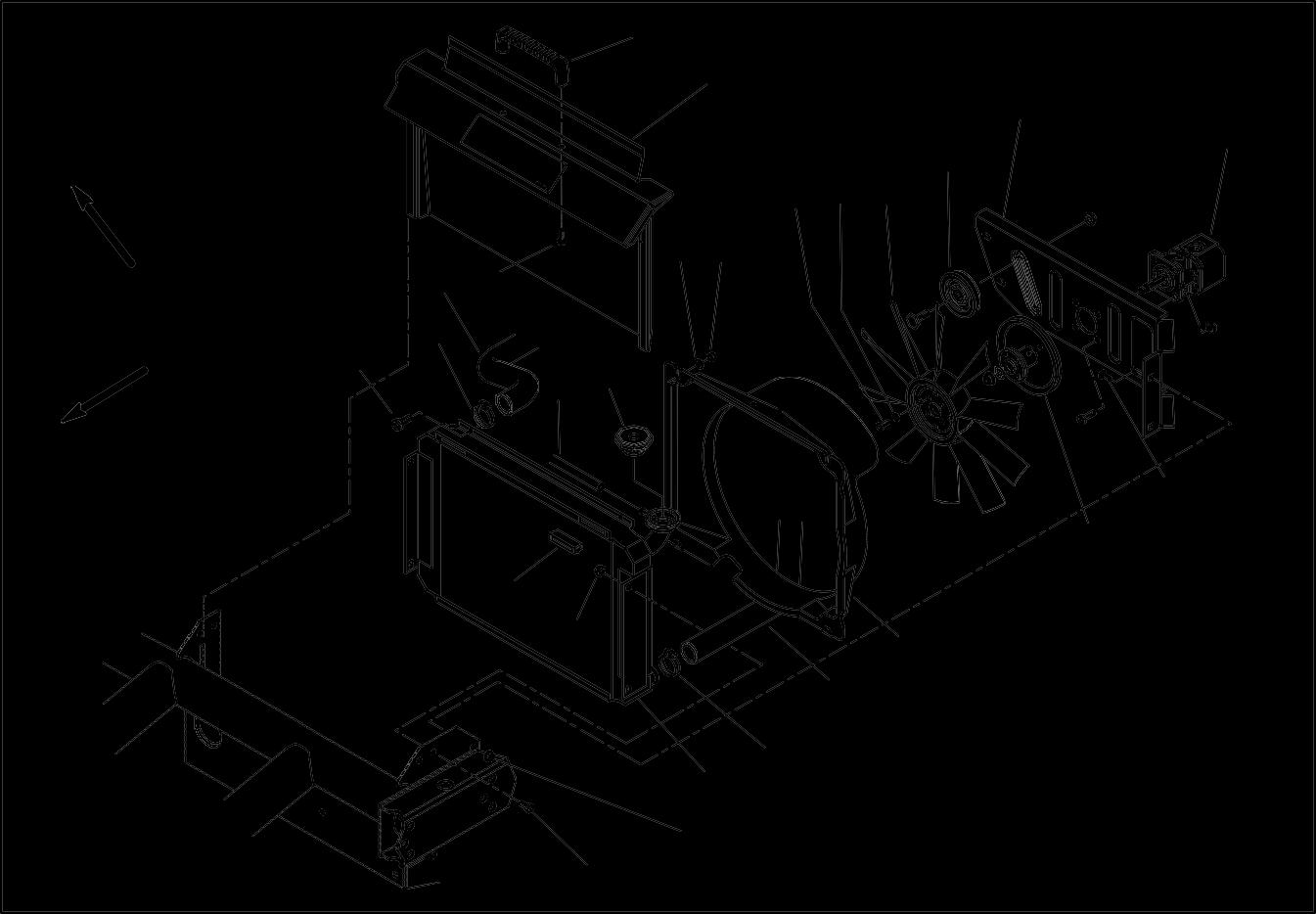
Removal (Fig. 5)
Advertisement
1. Park vehicle on a level surface, stop engine, engage parking brake, and remove key from the ignition switch. Allow engine to cool.
2. Raise or remove the bed or other attachment(s). If bed is raised, place safety support on lift cylinder (see Operator’s Manual).
3. Lift and remove the radiator screen from front of radiator.
Caution
Do not open radiator cap or drain coolant if the radiator or engine is hot. Pressurized, hot coolant can escape and cause burns.
Ethylene–glycol antifreeze is poisonous. Dispose of coolant properly, or store it in a properly labeled container away from children and pets.
4. Remove the radiator cap. Drain radiator into a suitable container using the radiator drain located on the lower right corner of the radiator.
5. Disconnect upper and lower radiator hoses from the radiator.
6. Disconnect reservoir hose (item 13) from the radiator filler neck.
7. Detach fan shroud from the radiator by removing four (4) cap screws, flat washers and lock nuts. Position shroud away from radiator.
8. Remove four (4) cap screws and flange nuts that secure the radiator to the frame. Pull radiator from the vehicle.
9. Plug all radiator and hose openings to prevent contamination.
Installation (Fig. 5)
1. Remove plugs from radiator and hoses placed during the removal procedure.
2. Position radiator to the frame. Secure radiator to the vehicle with four (4) cap screws and flange nuts.
3. Attach fan shroud to the radiator with four (4) cap screws, flat washers and lock nuts. Make sure that clearance exists between shroud and fan at all points.
4. Connect reservoir hose (item 11) to the radiator filler neck.
5. Connect upper and lower hoses to the radiator.
6. Make sure radiator drain is closed. Fill radiator with coolant (see Operator’s Manual).
7. Install the radiator screen.
8. Lower or install bed or other attachment(s).
Pump Driveshaft Service
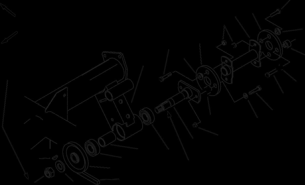
Removal (Fig. 6)
1. Park vehicle on a level surface, raise and support bed (if installed), shut engine off and engage the parking brake.
2. Disassemble driveshaft using Figure 6 as a guide.
3. Do not reuse bearings (Item 6) if they have been removed from frame support bracket. Replace with new bearings.
Inspection
1. Inspect frame support bracket for wear or damage.
2. Inspect bearing spacer (Item 7) for wear or damage. Also, check that spacer length is from 1.884” to 1.894” (47.85 to 48.10 mm). Replace spacer if necessary.
Installation (Fig. 6)
1. To install bearings (Item 6) into frame support bracket:
A. Install pulley side bearing into support bracket by pressing on bearing outer race until bearing contacts shoulder in support bracket.
B. Place the bearing spacer (Item 7) into bracket cavity.
C. Install second bearing into bracket by pressing on the bearing outer race until bearing inner race contacts spacer.
2. Slide shaft (Item 8) into installed bearings in frame support bracket. Apply antisieze lubricant to pulley end of shaft before installing woodruff key (Item 3) and pulley (Item 5).
3. Secure pulley to shaft with washer and lock nut. Torque lock nut from 100 to 130 in–lb (11.3 to 14.7 N–m). Make sure that shaft rotates freely after pulley is installed.
4. Assemble driveshaft using Figure 6 as a guide.
5. Adjust pump drive belt tension after assembly (see Operator’s Manual).


