2 minute read
Briggs/Daihatsu Gasoline Engine


This Chapter gives information about specifications and repair of the Briggs & Stratton/Daihatsu 3LC gasoline engine used in the Workman 3200 and 4200.
General engine maintenance procedures are described in your Operator’s Manual. Information on engine troubleshooting, testing, disassembly, and reassembly is identified in the Briggs & Stratton/Daihatsu Repair Manual that is included at the end of this section.
Advertisement
Most repairs and adjustments require tools which are commonly available in many service shops. Special tools are described in the Briggs & Stratton/Daihatsu Repair Manual. The use of some specialized test equipment is explained. However, the cost of the test equipment and the specialized nature of some repairs may dictate that the work be done at an engine repair facility.
Service and repair parts for Briggs & Stratton/Daihatsu 3LC gasoline engines are supplied through your local Toro distributor.
General Information


Adding Oil to Engine
When adding oil to the engine, maintain clearance between the oil fill device and the oil fill opening in the valve cover (Fig. 1). This clearance is necessary to allow venting when adding engine oil which will prevent oil from running into the breather tube and intake system.
Adjustments
Engine Speed Adjustment
1. Park vehicle on a level surface, engage parking brake and place gear shift lever in neutral.
2. Raise the bed or remove attachment(s) to allow access to engine. If bed is raised, place safety support on lift cylinder (see Operator’s Manual).
3. Stop engine and remove key from the ignition switch.
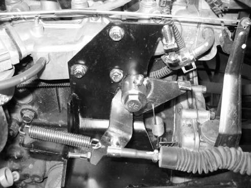
4. Make sure governor spring is assembled to bellcrank on throttle bracket and outer most slot in engine governor lever (Fig. 2).
5. Check lowidle stopscrew adjustment (Figs. 3,4 and 5). Proper low idle stop screw adjustment will prevent engine run on when the accelerator pedal is released:
A. Remove return spring from throttle bracket and bellcrank. Disconnect throttle cable from balljoint on bellcrank.
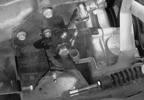
B. Move the governor lever to its rearmost position and check that the governor spring is loose in the slot on the engine governor lever. Also, check that the rear edge of the bellcrank is against the low idle stop screw. Release governor lever.
C. Position the rear edge of the bellcrank so it is 0.125 in. (3.2 mm) from the head of the low idle stop screw (Fig. 4). At this position, the governor spring must be tight against the upper edge of the engine governor lever slot with no extension of the spring coils. If necessary, adjust low idle stop screw and/or governor spring adjusting rod (if equipped) to allow correct governor spring positioning.
D. Install return spring to throttle bracket and bellcrank. Connect throttle cable to balljoint on bellcrank.
6. Check operation and adjustment of accelerator cable (see Operator’s Manual). If needed, adjust accelerator cable.
7. Start andrun engine until engineis atnormal operating temperature. Make sure that carburetor choke is fully open.
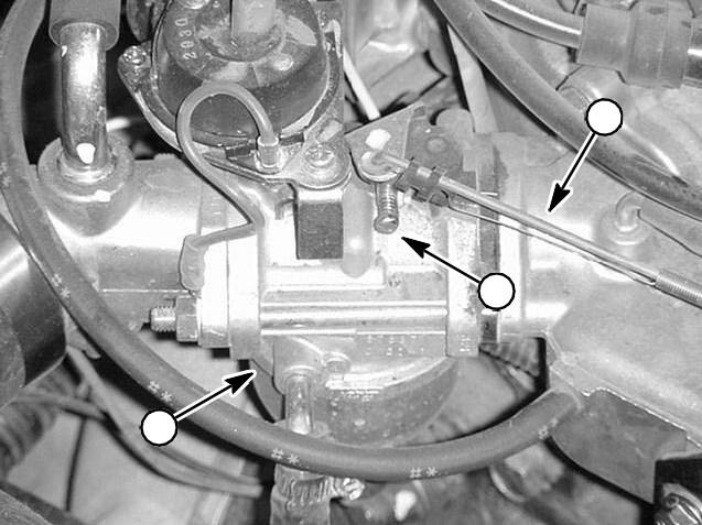
8. Using a tachometer, check low idle speed. Low idle speed should be 1100 + 50 RPM. If low idle is incorrect, repeat idle stop screw adjustment (step 5). If low idle is still incorrect, adjust the idle speed screw on the carburetor to obtain 1100 + 50 RPM (Fig. 6).
9. Check high idle speed. High idle speed should be 3600 + 50 RPM. Reposition the high idle stop screw to adjust high idle speed. Make sure to tighten lock nut after adjusting high idle stop screw.
10.After engine speed adjustments are complete, lower the bed or install attachment(s).


