TEREX Equipment Limited Maintenance Manual 15503431 SM917/865 MAINTENANCE
TA35TA40 G7
DOWNLOAD SERVICE MANUAL
MANUAL

CLICK HERE FOR TABLE OF CONTENTS
THIS PAGE IS INTENTIONALLY LEFT BLANK
MAINTENANCE MANUAL TA3540 G7 TEREX Equipment Limited Maintenance Manual Re- Order Issued by; Customer Support Department Terex Equipment Limited Newhouse Industrial Estate Motherwell, ML1 5RY Scotland Tel; +44 (0) 1698 732121 Fax; +44 (0) 1698 503210 www.terex.com Technical Assistance: http://constructionsupport.terex.com SM917/865 Re-Order Part Number 15503431 revision July 2007
THIS PAGE IS INTENTIONALLY LEFT BLANK
TEREX Equipment Limited Maintenance Manual - Introduction
For further information on the subject matter detailed within this Maintenance Manual, please refer to Terex Equipment Limited Operator Handbooks and Product Parts Books.
Alternatively, please contact;
Customer Support Department
Terex Equipment Limited
Newhouse Industrial Estate Motherwell, ML1 5RY
Tel; +44 (0) 1698 732121
Fax; +44 (0) 1698 503210
The illustrations, technical information, data and descriptive text in this manual, to the best of our knowledge, were correct at the time of print. The right to change specifications, equipment and maintenance instructions at any time without notice, is reserved as part of the Terex Equipment Limited policy of continuous development and improvement of the product.
No part of this publication may be reproduced, transmitted in any form - electronic, mechanical, photocopying, recording, translating or by any other means without prior permission of Customer Support Department - Terex Equipment Limited.
Please refer to TEREX Specification Sheets or consult Factory Representatives to ensure that information is current.
MAINTENANCE MANUAL TA35TA40
G7
THIS PAGE IS INTENTIONALLY LEFT BLANK
IMPORTANT SAFETY NOTICE
Proper service and repair is important to the safe, reliable operation of all motor vehicles. The service procedures recommended and described in this publication, are effective methods forperforming service operations. Some of these service operations require the use of tools specially designed for the purpose. The special tools should be used when, and as recommended.
It is important to note that this publication contains various WARNINGS and NOTES which should be carefully read in order to minimize the risk of personal injury to personnel, or the possibility that improper service methods will be followed which may damage the vehicle or render it unsafe. It is also important to understand these WARNINGS and NOTES are not exhaustive. It is not possible to know, evaluate and advise the service trade of ALL conceivable ways in which service might be carried out, or, of the possible hazardous consequences of each way. Consequently, no such broad evaluation has been undertaken. Accordingly, anyone who uses a service procedure, or tool, which is not recommended, must first satisfy themselves thoroughly that neither their safety, nor vehicle safety, will be jeopardized by the service method he/she selects.
SafetyAlertSymbol


The safety alert symbol is used to alert you to a potential personal injury hazards. Obey all safety messages that follow this symbol to avoid possible injury or death.
HazardClassification
A multi-tier hazard classification system is used to communicate potential personal injury hazards. The following signal words used with the safety alert symbol indicate a specific level of severity of the potential hazard. Signal words used without the safety alert symbol relate to property damage and protection only. All are used as attention getting devices throughout this manual as well as on deals and labels fixed to the machinery to assist in potential hazard recognition and prevention.
DANGER indicates an imminently hazardous situation which, if not avoided, will result in death or serious injury.
WARNING indicates an potentially hazardous situation which, if not avoided, could result in death or serious injury.
CAUTION indicates an potentially hazardous situation which, if not avoided, may result in minor or moderate injury.
CAUTION used without the safety alert symbol indicates a potentially hazardous situation which, if not avoided, may result in property damage.
WARNING
Never use parts which are altered, modified, or weakened in operation. This can seriously jeopardise the integrity of the machine and could result in property damage or serious personal injury.
WARNING DANGER CAUTION CAUTION
SM 2495 03-07
THIS PAGE IS INTENTIONALLY LEFT BLANK
TABLE OF CONTENTS
2 SM 2497 Rev01 07-07
Section No. Description SM No. 000 0000 0000 0010 GENERALINFORMATION Technical Data - TA35 Technical Data - TA40 WeldingProcedure 2498 2436Rev2 2172 100 0010 0020 0040 CHASSIS Frames Articulation and Oscillation Pivot HoodandMounting 2403 2438 2383Rev1 110 0030 0050 ENGINE EngineandMounting AirCleaner 2384 2404 120 0010 0090 TRANSMISSION TransmissionandMounting TransmissionPTO 2416Rev1 2371 125 0010 0020 DROPBOX DropboxandMounting EmergencySteeringPump 2367Rev4 2369 130 0010 0020 DRIVELINES FrontDrivelines RearDrivelines 2385 2386 140 0020 0040 0060 FRONTAXLEGROUP AxleGroup(Hub) (RefertoSection160-0030) WheelRim and Tyre (RefertoSection160-0050) DifferentialDriveHead (RefertoSection160-0020)-150 0020 CENTREAXLE DifferentialDriveHead 2249 160 0020 0030 0050 REARAXLEGROUP DifferentialDriveHead AxleGroup(Hub) Wheel Rim and Tyre 2248 2408Rev1 2389Rev1 165 0015 BRAKEASSEMBLY Oil Cooled Disc Brakes 2390 170 0010 PARKINGBRAKE ParkingBrake andMounting 2428 180 0020 0040 SUSPENSION SYSTEM FrontSuspension RearSuspension 2391 2392 190 0000 0085 0270 ELECTRICAL SYSTEM Circuit Diagrams (DDEC V, 4000Series transmission) Hydraulic System ECU Switches and Sensors 2439Rev1 2443Rev1 2368Rev2 200 0040 0051 FUEL SYSTEM Fuel System Electronic Foot Pedal 2394 2395
TABLE OF CONTENTS
SM 2497 Rev01 07-07 1
Section No. Description SM No. 210 0000 0005 0010 0040 0044 0050 0060 0065 0100 COOLING SYSTEM Cooling System (Series 60 Engine) Cooling System Schematic Cooling Fan and Motor RadiatorsandMounting Fan Disconnect Valve Disc Brake Oil Cooler TransmissionOilCoolers DropboxOilCooler Hydraulic Oil Cooler 2260 2397 2458 Rev 1 2445Rev1 2457 2153 2433Rev1 2432 2459 215 0050 MAINHYDRAULICVALVE Main Hydraulic Valve Assembly 2442Rev2 220 0000 0090 0120 STEERING SYSTEM Steering System Schematic SteeringValve SteeringCylinder 2423Rev1 2364 2399 230 0000 0040 0050 0081 0130 BODY SYSTEM Body System Schematic HydraulicTank (RefertoSection250-0025) Main Hydraulic Pump BodyControlLever BodyCylinder 2441Rev12370Rev2 2418 2402 250 0000 0025 0045 0050 0060 0070 0075 BRAKING SYSTEM Braking System Schematic Brake Coolant / Hydraulic Tank Motor/Triple Pump Assembly Brake Manifold Valve Accumulator TreadleValve OCDBReliefUnloaderValve 2430Rev1 2447Rev2 2422 2456 2431 2427 2426 260 0010 0090 0130 OPERATORS COMPARTMENT Cab and Mounting Driver Seat and Mounting AirConditioning 2388 2400 2460Rev1 270 0010 BODY BodyandMounting 2429 300 0020 0070 0080 0090 MISCELLANEOUS LubricationSystem Service Tools Standard Bolt and Nut Torque Specifications UnitStorage 2435Rev4 2437 1238 1239 * * * *
ENGINE
Make/Model Detroit Diesel Series 60 Type 6 Cylinder, in line , Four cycle diesel, water cooled, turbocharged with air to air cooling, electronic engine management.
Gross power at 2 110 rev/min....... 298 kW (400 hp, 405 PS)
Net power at 2 110 rev/min 389 kW (388 hp, 393 PS)
Note: Gross power rated to SAE J1995 Jun 90. Engine emission meets USA EPA Tier 3 /CARB MOH 40 CFR 89 Tier 3 and proposed EU NRMM (non-road mobile machinery) Tier 3 directive.
Maximum Torque 2 000 Nm (1475 lbf ft) at 1 200 rev/min
Number of cylinders/configuration 6, in line
Bore x Stroke 133 x 168 mm (5.24 x 6.61 in)
Piston Displacement 14 litres (855 in³)
Air cleaner Dry type, double element
Electric
Make/Model
4500 ORS with integral retarder mounted directly to the engine, fully automatic transmission with planetary gearing, lock-up in all gear ranges. Electronic control with six forward and one reverse gear.

Technical
TA35
SM 2498 03-07 1
General Information -
Data
Section 000-0000
Starting
Maximum Speed (No load) 2 300 rev/min Maximum Speed (Full load) 2 200 rev/min Idle Speed 700 rev/min Safe Operating Angle 43°/94% Grade
TRANSMISSION
Allison
Main 18.5 + 3.4 bar (269
50 lbf/in²) Temperatures: Normal 60° - 135° C
Maximum
Ratios: Transmission Refer to table below Low Range Forward Gear 1 2 3 4 5 6 km/h 5.2 11.0 15.9 24.3 31.0 35.2 mile/h 3.2 6.8 9.9 15.1 19.3 21.9 Reverse Gear 1 km/h 4.6 mile/h 2.9 HighRange SM - 3528 Max 1 495 Body (4-11)Depth 3 315 (10-11) 3 130 (10-3) 6 930 (22-9) 66˚ 3 945 (12-11) 3 740 (12-3) 3 550 (11-8) 3 140 (10-4) 2 470 (8-1) 605 (2-0) 1 840 (6-0) 2 595 (8-6) 3 360 (11-3) 905 (2-9) 3 025 (9-11) 1 310 (4-4) 2 990 (9-10) 11 055 (36-3) 1 950 (6-5) 1 780 (5-10) Dimensions in mm (ft-in)
+
(140° - 275° F)
165° C (329° F)
Forward Gear 1 2 3 4 5 6 km/h 7.9 16.8 24.3 37.1 47.7 53.9 mile/h 4.9 10.4 15.1 23.1 29.6 33.5 Reverse Gear 1 km/h 7.0 mile/h 4.3
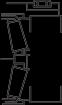
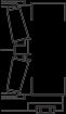
Fig. 1 - Machine Dimensions
General Information - Technical Data TA35
Section 000-0000
DROPBOX
Remote mounted transfer gearbox taking drive from the transmission and feeding it via a lockable differential to the front and rear wheels.
AXLES
Three axles in permanent all-wheel drive (6 X 6) with differential coupling between each axle to prevent driveline wind-up. Heavy duty axles with fully-floating axle shafts and outboard planetary reduction gearing.
Automatic limited slip differentials in each axle. Centre axle incorporates a through-drive differential to transmit drive to the rear axle. This differential and the dropbox output differential are locked simultaneously using one switch selected by the operator.
HYDRAULIC SYSTEM
Braking, steering and body hoist systems are controlled by a main hydraulic valve mounted on frame. Systems are supplied with oil from a common tank by the main hydraulic pump, driven from power takeoff on transmission. System components are protected by full flow filtration on the return line.
Pump: Type Piston Capacity at 2 700 rev/min 5.4 litre/s (85.6 US gal/min)
Brakes
Full hydraulic braking system with enclosed, forced oilcooled multiple discs on each wheel. Independent circuits for front and rear brake systems. Warning lights and audible alarm indicate low brake system pressure. Brake system conforms to ISO 3450, SAE J1473.
Actuating Pressure 48 ± 2.4 bar (700 ± 35 lbf/in²)
Pump Type Triple stage gear Capacity at 1 685 rev/min 8.9 litre/s (2.35 US gal/min)
SUSPENSION
Front: Four trailing links and a panhard rod locate the front axle giving a high roll centre. The optimised front axle position along with the wide spaced main and rebound mounts, mounted directly above the axle and long suspension travel, combine with two heavy duty dampers each side to give excellent handling and ride.
Rear: Each axle is coupled to the frame by three rubberbushed links with lateral restraint by a transverse link. Pivoting inter-axle balance beams equalise load on each axle. Suspension movement is cushioned by rubber/metal laminated compression units between each axle and underside of balance beam ends. Pivot points on rear suspension linkages are rubber-bushed and maintenancefree.
WHEELS AND TYRES
Wheels: 5-piece earthmover rims with 12 stud fixing
Size: Standard 25 x 22.00 in for 26.5 R25** tyres
Tyres: Standard 26.5 R25**
Inflation Pressures (Bridgestone): Front Centre/Rear 26.5 R25** 3.73 bar (54 lbf/in²) 4.97 bar (72 lbf/in²)
Inflation Pressures (Michelin): Front Centre/Rear 26.5 R25** 3.24 bar (47 lbf/in²) 4.28 bar (62 lbf/in²)
Inflation Pressures (GoodYear): Front Centre/Rear
26.5 R25** 4.75 bar (69 lbf/in²) 4.75 bar (69 lbf/in²)
Note: Tyre pressures should be regarded as nominal only. It is recommended that for tyres both listed and unlisted, the user should consult the tyre manufacturer and evaluate all job conditions in order to make the proper selection.
Braking surface (tractor) 590240 mm2 (914.9 in2)/brake
Braking surface (trailer) 590240 mm2 (914.9 in2)/brake
Parking: Spring-applied, hydraulic-released disc on rear driveline.
Emergency: Automatic application of driveline brake should pressure fall in main brake hydraulic system. Service brakes may also be applied using the parking-emergency brake control.
Retardation: Hydraulic retarder integral with transmission.
Steering
Hydrostatic power steering by two single-stage, doubleacting, cushioned steering cylinders. Emergency steering pressure is provided by a ground driven pump mounted on the rear of the transmission. An audible alarm and warning light indicates should the emergency system activate. Conforms to ISO 5010, SAE J53.
System Pressure 240 bar (3 500 lbf/in²) Steering Angle to either side 45° Lock to Lock Turns, steering wheel 4
Body Hoist
Two single-stage, double-acting hoist rams, cushioned at both ends of stroke. Electro servo assisted hoist control.
System Pressure 240 bar (3 500 lbf/in²) Control Valve Pilot Operated, Closed Centre Body Raise Time (loaded).......................................12.5 sec Body Lower Time (power down)...................................8 sec
ELECTRICAL SYSTEM
Type 24 volt, Negative Ground Battery Two, 12 Volt, 175 Ah each Accessories 24 Volt Alternator 100 Amp
2 SM 2498 03-07
Ratios: Differential 3.70:1 Planetary 6.35:1 Total Reduction 23.50:1
BODY
Of all welded construction, fabricated from high hardness (min. 360 BHN) 1 000 MPa (145 000 lbf/in²) yield strength steel. 25° tail chute angle provides good load retention without tailgate.
* - The above result is for the mode giving the highest exterior sound level when measured and operated as per the prescribed procedures of the standard. Results shown are for the vehicle in base configuration.
Note: Noise Level Exposure to the operator and bystander personnel may be higher depending upon proximity to buildings, rock piles, machinery etc.. The actual job site Noise Level Exposure must be measured and applicable regulations complied with in respect to Employee Hearing Protection.
Technical
SM 2498 03-07 3
General Information -
Data TA35 Section 000-0000
Plate Thicknesses: Floor and Tailchute 15 mm (0.58 in) Sides 12 mm (0.47 in) Front 8 mm (0.39 in) Volume: Struck (SAE) 15.5 m³ (20.3 yd³) Heaped 2:1 (SAE) 21.0 m³ (27.5 yd³) SERVICE CAPACITIES Fuel tank 481 litres (127 US gal) Hydraulic System 330 litres (87.2 US gal) Cooling System ..................................80 litres (21.1 US gal) Engine Crankcase (with filters) 37 litres (9.8 US gal) Transmission (with filters) 61 litres (14.8 US gal) Differentials - Front & Rear 33 litres (8.9 US gal) Differentials - Centre 34 litres (8.7 US gal) Planetaries (each) 9 litres (2.4 US gal) Driveshaft Bearings 1.5 litres (0.4 US gal) Air Conditioning Compressor 0.125 litres (0.033 US gal) TYPICAL NOISE LEVELS Operator Ear (ISO 6394) 76 dbA
109 dbA
*Exterior Sound Rating (ISO 6395)
Vehicle Weights 29.5 R25 Tyres Standard Vehicle kg lb NetDistribution Front Axle 15 086 32 258 Centre Axle 7 125 15 707 Rear Axle 7 068 15 582 Vehicle, Net 29 279 64 547 Payload 34 000 74 956 GrossDistribution Front Axle 17 279 38 094 Centre Axle 23 000 50 705 Rear Axle 23 000 50 705 Vehicle, Gross 63 279 139 506 Bare Chassis 23 669 52 177 Body 4 950 10 915 Body Hoists (Pair) 660 1 455
* * * *
THIS PAGE IS INTENTIONALLY LEFT BLANK
ENGINE
Make/Model Detroit Diesel Series 60 Type 6 Cylinder, in line , Four cycle diesel, water cooled, turbocharged with air to air cooling, electronic engine management.
Gross power at 2 110 rev/min....... 338 kW (454 hp, 460 PS)
Net power at 2 110 rev/min 326 kW (437 hp, 443 PS)
Note: Gross power rated to SAE J1995 Jun 90. Engine emission meets USA EPA Tier 3 /CARB MOH 40 CFR 89 Tier 3 and proposed EU NRMM (non-road mobile machinery) Tier 3 directive.
Maximum Torque 2 100 Nm (1548 lbf ft) at 1 350 rev/min
Number of cylinders/configuration 6, in line
Bore x Stroke 133 x 168 mm (5.24 x 6.61 in)
Piston Displacement 14 litres (855 in³)
Air cleaner Dry type, double element
Electric
Make/Model
4500 ORS with integral retarder mounted directly to the engine, fully automatic transmission with planetary gearing, lock-up in all gear ranges. Electronic control with six forward and one reverse gear.
- Technical Data TA40
SM 2436 Rev2 03-07 1
General Information
Section 000-0000
Starting
Maximum Speed (No load) 2 300 rev/min Maximum Speed (Full load) 2 200 rev/min Idle Speed 700 rev/min Safe Operating Angle 43°/94% Grade
TRANSMISSION
Main 18.5 + 3.4 bar (269
Temperatures: Normal 60° - 135°
Maximum
Ratios: Transmission
to table below Low Range Forward Gear 1 2 3 4 5 6 km/h 5.5 11.7 16.9 25.8 33.0 37.5 mile/h 3.4 7.3 10.5 16.0 20.5 23.3 Reverse Gear 1 km/h 4.8 mile/h 3.0 High Range SM - 3528 Max 1 495 Body (4-11)Depth 3 315 (10-11) 3 130 (10-3) 6 930 (22-9) 66˚ 3 945 (12-11) 3 740 (12-3) 3 550 (11-8) 3 140 (10-4) 2 470 (8-1) 605 (2-0) 1 840 (6-0) 2 595 (8-6) 3 360 (11-3) 905 (2-9) 3 025 (9-11) 1 310 (4-4) 2 990 (9-10) 11 055 (36-3) 1 950 (6-5) 1 780 (5-10) Dimensions in mm (ft-in)
Allison
+ 50 lbf/in²)
C (140° - 275° F)
165° C (329° F)
Refer
Forward Gear 1 2 3 4 5 6 km/h 8.4 17.8 25.8 39.5 50.4 60.0 mile/h 5.2 11.0 16.0 24.5 31.3 37.3 Reverse Gear 1 km/h 7.4 mile/h 4.6
Fig. 1 - Machine Dimensions
General Information - Technical Data TA40
Section 000-0000
DROPBOX
Remote mounted transfer gearbox taking drive from the transmission and feeding it via a lockable differential to the front and rear wheels.
AXLES
Three axles in permanent all-wheel drive (6 X 6) with differential coupling between each axle to prevent driveline wind-up. Heavy duty axles with fully-floating axle shafts and outboard planetary reduction gearing.
Automatic limited slip differentials in each axle. Centre axle incorporates a through-drive differential to transmit drive to the rear axle. This differential and the dropbox output differential are locked simultaneously using one switch selected by the operator.
HYDRAULIC SYSTEM
Braking, steering and body hoist systems are controlled by a main hydraulic valve mounted on frame. Systems are supplied with oil from a common tank by the main hydraulic pump, driven from power takeoff on transmission. System components are protected by full flow filtration on the return line.
Pump: Type Piston Capacity at 2 700 rev/min 5.4 litre/s (85.6 US gal/min)
Brakes
Full hydraulic braking system with enclosed, forced oilcooled multiple discs on each wheel. Independent circuits for front and rear brake systems. Warning lights and audible alarm indicate low brake system pressure. Brake system conforms to ISO 3450, SAE J1473.
Actuating Pressure 48 ± 2.4 bar (700 ± 35 lbf/in²)
Pump Type Triple stage gear Capacity at 1 685 rev/min 8.9 litre/s (2.35 US gal/min)
SUSPENSION
Front: Four trailing links and a panhard rod locate the front axle giving a high roll centre. The optimised front axle position along with the wide spaced main and rebound mounts, mounted directly above the axle and long suspension travel, combine with two heavy duty dampers each side to give excellent handling and ride.
Rear: Each axle is coupled to the frame by three rubberbushed links with lateral restraint by a transverse link. Pivoting inter-axle balance beams equalise load on each axle. Suspension movement is cushioned by rubber/metal laminated compression units between each axle and underside of balance beam ends. Pivot points on rear suspension linkages are rubber-bushed and maintenancefree.
WHEELS AND TYRES
Wheels: 5-piece earthmover rims with 12 stud fixing
Size: Standard 25 x 25.00 in for 29.5 R25** tyres
Tyres: Standard 29.5 R25**
Inflation Pressures (Bridgestone): Front Centre/Rear 29.5 R25** 4.0 bar (76 lbf/in²) 5.0 bar (73 lbf/in²)
Inflation Pressures (Michelin): Front Centre/Rear 29.5 R25** 2.76 bar (40 lbf/in²) 3.80 bar (55 lbf/in²)
Inflation Pressures (GoodYear): Front Centre/Rear
29.5 R25** 3.24 bar (47 lbf/in²) 4.6 bar (66 lbf/in²)
Note: Tyre pressures should be regarded as nominal only. It is recommended that for tyres both listed and unlisted, the user should consult the tyre manufacturer and evaluate all job conditions in order to make the proper selection.
Braking surface (tractor) 590240 mm2 (914.9 in2)/brake
Braking surface (trailer) 590240 mm2 (914.9 in2)/brake
Parking: Spring-applied, hydraulic-released disc on rear driveline.
Emergency: Automatic application of driveline brake should pressure fall in main brake hydraulic system. Service brakes may also be applied using the parking-emergency brake control.
Steering
Hydrostatic power steering by two single-stage, doubleacting, cushioned steering cylinders. Emergency steering pressure is provided by a ground driven pump mounted on the rear of the transmission. An audible alarm and warning light indicates should the emergency system activate. Conforms to ISO 5010, SAE J53.
System
Body Hoist
bar (3
Two single-stage, double-acting hoist rams, cushioned at both ends of stroke. Electro servo assisted hoist control.
System Pressure 240 bar (3 500 lbf/in²) Control Valve Pilot Operated, Closed Centre Body Raise Time (loaded)
Body Lower Time (power down)
ELECTRICAL SYSTEM
2 SM 2436 Rev2 03-07
Ratios: Differential 3.70:1 Planetary 6.35:1 Total Reduction 23.50:1
Pressure 240
500 lbf/in²) Steering Angle to either side 45° Lock to Lock Turns, steering wheel 4
13 sec
7.5 sec
Accessories 24
100
Type 24 volt, Negative Ground Battery Two, 12 Volt, 175 Ah each
Volt Alternator
Amp
BODY
Of all welded construction, fabricated from high hardness (min. 360 BHN) 1 000 MPa (145 000 lbf/in²) yield strength steel. 25° tail chute angle provides good load retention without tailgate.
* - The above result is for the mode giving the highest exterior sound level when measured and operated as per the prescribed procedures of the standard. Results shown are for the vehicle in base configuration.
Note: Noise Level Exposure to the operator and bystander personnel may be higher depending upon proximity to buildings, rock piles, machinery etc.. The actual job site Noise Level Exposure must be measured and applicable regulations complied with in respect to Employee Hearing Protection.
Technical
TA40
SM 2436 Rev2 03-07 3
General Information -
Data
Section 000-0000
Plate Thicknesses: Floor and Tailchute 15 mm (0.58 in) Sides 12 mm (0.47 in) Front 10 mm (0.39 in) Volume: Struck (SAE) 17.4 m³ (22.8 yd³) Heaped 2:1 (SAE) 23.3 m³ (30.3 yd³) SERVICE CAPACITIES Fuel tank 481 litres (127 US gal) Hydraulic System 330 litres (87.2 US gal) Engine Crankcase and filters................32 litres (8.4 US gal) Cooling System 67 litres (17.7 US gal) Transmission (including cooler) 61 litres (2.6 US gal) Dropbox 13 litres (8.7 US g Differentials - Front & Rear (each) 33 litres (8.7 US gal) Differential - Centre 34 litres (8.9 US gal) Planetaries (each) 9 litres (2.37 US gal) Hand Pump Tank 1 litres (0.26 US gal) Air Conditioning Compressor 0.125 litres (0.033 US gal) TYPICAL NOISE LEVELS Operator Ear (ISO 6394) 76 dbA
Sound Rating (ISO 6395) 109 dbA
*Exterior
* * * * Vehicle Weights 29.5 R25 Tyres Standard Vehicle kg lb NetDistribution Front Axle 15 880 34 936 Centre Axle 7 500 16 500 Rear Axle 7 440 16 368 Vehicle, Net 30820 67 804 Payload 38 000 83 775 GrossDistribution Front Axle 18 320 41 500 Centre Axle 25 000 55 000 Rear Axle 25 000 55 000 Vehicle, Gross 68 320 151 500 Bare Chassis 24 760 54 444 Body 5 400 11 905 Body Hoists (Pair) 660 1 455
THIS PAGE IS INTENTIONALLY LEFT BLANK
Welding
WARNINGS
Before any welding is done on a machine equipped with any electronic systems, disconnect the following (if applicable) in this order: Battery earth cable, battery supply cable, alternator earth cables, alternator supply cables and electrical connections at the engine ECM, transmission ECU, body control lever, hydraulics ECU and cab bulkhead to avoid damage to electrical components. Turn off battery master switch to isolate the batteries before disconnecting any components. After welding connect all of the above in the reverse order.
WARNING
Welding and flame cutting cadmium plated metals produce odourless fumes which are toxic. Recommended industrial hygiene practice for protection of the welding operator from the cadmium fumes and metallic oxides requires enclosure ventilation specifically designed for the welding process. A respiratory protective device such as the M.S.A. 'Gasfoe' respirator with G.M.A. cartridge will provide protection against cadmium, fumes and metallic oxides. The 'Gasfoe' respirator has been approved by the U.S. Bureau of Mines: Approval number 23B-10, and is designed to protect against gases, vapours, and/or metal fumes.
Before any welding is done ensure all paint has been removed from the area to be welded. Failure to do so may result in hazardous fumes being given off from the paint.
Note: Always fasten the welding machines ground cable to the piece/frame being welded if possible.
Electric arc welding is recommended for all welded frame repairs. Since the nature and extent of damage to the frame cannot be predetermined, no definite repair procedure can be established. As a general rule however, if parts are twisted, bent or pulled apart, or a frame is bent or out of alignment, no welding should be done until the parts are straightened or realigned.
Successfully welded repairs will depend to a great extent upon the use of the proper equipment, materials and the ability of the welder. The Customer Support Department can be consulted regarding the feasibility of welding repairs.
Note: The current from the welding rod always follows the path of least resistance. If, for example, the ground clamp is attached to the rear frame when welding is performed on the front frame, the current must pass a frame connection to return to the welding machine. Since the pivot coupling offers the least resistance but not a sound electrical connection, small electric arcs may be set up across the moving parts which may cause welding blotches on their wearing surfaces and increase the wear rate of these components.
General Welding Procedure
The following general procedure should be used for the repair of defects outwith the vicinity of alloy steel castings.
1. Completely ARC-AIR gouge or grind out the crack until sound metal is reached. If ARC-AIR method is employed, pre-heat area to 100° C (212° F), measure 3 - 4" either side of repair prior to gouging. On completion of gouging grind to remove thin carbon layer
2. Apply dye-penetrant check to ensure crack has been completely removed.
GENERAL INFORMATION - Welding Procedure 1 SM 2172 11-05
Section 000-0010
General Information - Welding Procedure
Section 000-0010
3. Pre-heat area to 100° C (212° F), measured 3 - 4" either side of repair. Avoid local overheating.
4. Weld completely using E-7016 electrodes. Care must be taken to ensure electrodes are protected from moisture pick-ups at all times.
5. Allow repair weld to cool slowly.
6. Grind and blend repair to original contour. Paint heat damaged areas.
The following general procedure should be used for the repair of defects in alloy steel castings and in the welds joining steel castings.
1. Completely ARC-AIR gouge or grind out the crack until sound metal is reached. If ARC-AIR method is employed, pre-heat area to 200° C (392° F), measure
3 - 4" either side of repair prior to gouging. On completion of gouging grind to remove thin carbon layer.
2. Apply dye-penetrant check to ensure crack has been completely removed.
3. Pre-heat area to 200° C (392° F), measured 3 - 4" either side of repair. Avoid local overheating.
4. Weld completely using E-7016 electrodes. Care must be taken to ensure electrodes are protected from moisture pick-ups at all times.
5. On completion of welding, post-heat repair area to 400° C (752° F), measure 3 - 4" either side of repair.
6. If welding has to be interrupted for any reason, e.g. overnight, post-heat immediately as in Step 5.
2 SM 2172 11-05
* * * *
DESCRIPTION
The front and rear frames are all-welded high grade steel fabrications, with rectangular box section beams forming the main side and cross-members. These heavy duty structures are designed to withstand the severe loadings incurred when operating over rough terrain.
The front frame houses engine, transmission, hydraulic and fuel tanks and carries the cab, front suspension and front drive axle. The rear frame carries the body, body cylinders, rear suspension system and the rear drive axles.
Inter-frame oscillation is provided by a robust cylindrical coupling, carried on large nylon bushes. Steering is by frame articulation to 45 degrees either side by two widely spaced vertical pivot pins in taper rollerbearings.
SM 2403 01-06
CHASSIS - Frames

Section 100-0010 SM-3413


Note: For details on the articulation and oscillation pivot and procedures for separating the front and rear frames, refer to Section 100-0020, ARTICULATION AND OSCILLATION PIVOT.


MAINTENANCE
Note: This section covers maintenance of the front and rear frames only.
Inspection
Inspect the frames and attached parts at intervals not exceeding 250 hours for cracked or broken welds and bending of the frame. Any defects found should be repaired before they progress into major failures.
1
Fig. 1 - General Arrangement of Frame Assemblies
Chassis - Frames
Section 100-0010
Straightening
If the frame is not too badly sprung or twisted, hydraulicstraighteningandaligningequipmentcanbe used to straighten the frame without dismantling the machine. However, if the frame is severely damaged, it will be necessary to disassemble the machine in order to repair or replace the frame assembly.
All straightening operations should be performed without application of heat if possible. If heat must be applied, do not heat the metal beyond a dull cherry red colour, as it will result in serious weakening of the frame by decreasing the tensile strength of the steel. When it is necessary to apply heat, apply it uniformly over the area to be straightened until the metal reaches a uniform colour. Protect the heated surface from drafts to prevent sudden cooling of the metal. If the frame or frame parts cannot be straightened they must be replaced.
Welding
WARNINGS
Before any welding is done on a machine equipped with the DDEC system, disconnect wiring harnesses at the ECM, connections at body hydraulics joystick, all battery connections at both positive and negative terminals and ground cable to alternator to avoid damage to electrical components. Turn battery master switch to the 'Off' position before disconnecting any components. Remove battery ground cable first, and reconnect last, to avoid damaging electrical components.
Before any welding is done ensure all paint has been removed from the area to be welded. Failure to do so may result in hazardous fumes being given off from the paint.
Note: Prior to welding, switch off/disconnect the following in the order given. Failure to do so may seriously damage the machines electrical components.
a - Turn keyswitch off
b - Turn battery master switch off
c - Battery earth cables
d - Battery supply cables
e - Alternatorearthcables
f - Alternatorsupply cables
g - ECM Vehicle (both 68 pin connectors)
h - TransmissionTCM(80 pinconnector)
i- Transmission(4thGen)connector
j- HydraulicECUElectronicController
k - Body hydraulics joystick
l- VDU panelCPU(allconnectors)
After welding, connect all of the above in the reverse order.
Note: Always fasten the welding machines ground cable to the piece/frame being welded if possible.
Electric arc welding is recommended for all welded frame repairs. Since the nature and extent of damage to the frame cannot be predetermined, no definite repair procedure can be established. As a general rule however, if parts are twisted, bent or pulled apart, or a frame is bent or out of alignment, no welding should be done until the parts are straightened or realigned.
Successfully welded repairs will depend to a great extent upon the use of the proper equipment, materials and the ability of the welder. The Service Department can be consulted regarding the feasibility of welding repairs.
Reinforcement
Frame reinforcement can be made with channel, angle or flat structural stock. Whenever possible, the reinforcement should extend well beyond the bent, broken or cracked area. The reinforcement stock thickness should not exceed that of the frame stock and the material should be of the same tensile strength.
Painting
To keep rust and corrosion to a minimum, periodic painting of abrasions and other exposed metal areas on the frames is highly recommended.
If painting of a frame is required, thoroughly clean the areas to be painted. Apply a primer coat of synthetic red oxide and then a finish coat of synthetic enamel.
2 SM 2403 01-06
* * *
*
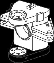
DESCRIPTION AND OPERATION


The articulation and oscillation pivot allows the front and rear frames to rotate horizontally (articulation) and tilt laterally (oscillation) with respect to each other. It is also the main load bearing coupling between the two frames. The pivot assembly houses the driveshaft


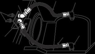


connecting the drive between the front and rear frames.
Articulation bearings, oscillation bushes, pivot driveshaft bearing and associated parts can be removed, inspected and replaced or renewed by following the procedures outlined in this section.


Articulation
SM-3533 1 SM 2438 01-06 16 50 51 29 19 14 8,9 17 DETAIL A 25 56 5,6 55 7 20 27 56 52 56 53 54 42 41 45,46,49 32 30 23 38 33 39 36,49 45,47,49 1 25 26,56 52,55 2,3,4 26,53 54,55 56 2,3,4 10,26 11 60 57,58,59 49,61,62 44,48,49 36,49 40 28 43 37,49 51 158,9 17 31 50 19 16 14 24 13 31 8,9 18 51 63 16 19 64-68 29 35 38 30,23 34 45,46,49 37,49 45,47,49 29 10,26 25 15 21,22 12 1 - Pivot Assembly 2 - Nylon Bush 3 - Loctite 648 4 - Loc Quick Primer 5 - Gasket 6 - Cover Plate 7 - Bolt 8 - Bearing Assy - Cup 9 - Bearing Assy - Cone 10 - 'V' Ring Seal 11 - Thrust Nut 12 - Locking Plate 13 - Antiseize Comp 14 - Driveshaft 15 - Seal 16 - Lockplate 17 - Front Yoke 18 - Brake Yoke 19 - Bolt 20 - Washer 21 - Lockwasher 22 - Bolt 23 - Extreme Pressure Lithium No.2Grease 24 - SAE 80W-90 EP Gear Oil 25 - Plug 26 - Extreme Pressure Multipurpose Grease 27 - Lube Fitting 28 - Plug 29 - 'O' Ring 30 - Bearing Assembly 31 - Retaining Ring 32 - Seal Housing 33 - Seal Housing 34 - Seal Housing 35 - Seal Housing 36 - Seal 37 - Seal 38 - Shim 39 - Spacer 40 - Upper Pin 41 - Washer 42 - Nut 43 - Lower Pin 44 - Hardened Washer 45 - Washer 46 - Bolt 47 - Bolt 48 - Bolt 49 - Loctite 243 50 - Thrustcollar-Front 51 - 'O' Ring 52 - Hose Assembly 53 - Hose Assembly 54 - Connector 55 - Lube Fitting 56 - Elbow 57 - Adaptor 58 - Connector 59 - Elbow 60 - Pipe Assembly 61 - Washer 62 - Bolt 63 - Thrust collar-Rear 64 - Shim 65 - Shim 66 - Shim 67 - Shim 68 - Shim
CHASSIS -
and Oscillation Pivot Section 100-0020
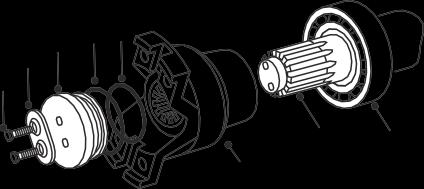
Fig. 1 - Articulation and Oscillation Pivot
Section 100-0020
THRU-DRIVE DRIVESHAFT
Numbers in parentheses refer to Fig. 1, unless otherwisespecified.
Note: The following procedures assume that only thru-drive components require repair.
Note: Tighten all fasteners without special torques specified to torques listed in Section 300-0080, STANDARD BOLT AND NUT TORQUE SPECIFICATIONS.
WARNINGS
To prevent personal injury and property damage, be sure wheel blocks are properly secured and of adequate capacity to do the job safely.
When necessary to drive out or drive on components during disassembly/assembly, be sure to use a soft drift to prevent property damage and personal injury.
Removal and Disassembly
1. Position the vehicle on a level work area and apply parking brake.
2. Raise body and install body safety prop to secure body in partially raised position.
3. Shut down engine and block all wheels securely.
4. Identify the relationship of the driveline caps to the transmission yoke and front yoke (17). Remove capscrews and remove driveline from vehicle.
Note: Take extra care when handling drivelines as any deformity on a rotating mass creates vibration and excessive wear during any operation.
5. Remove wheel blocks, start engine and steer vehicle into a full left-hand lock. Shut down engine and block all wheels securely.
6. Remove Lockplate (16) , 2 0ff Front bolts (19) & Front thrust collar (50).
7. Remove and discard 'O' rings (29 & 51) from Thrust collar (50).
8. Place a suitable container under the front of the pivot and pull front yoke (17) from driveshaft (14).
9.Disconnect mounting hardware securing protective guard (if fitted), from beneath the parking brake disc, to the rear frame.
10. Release the parking brake by turning the hex-head on the parking brake actuator fully anticlockwise.
WARNING
Tensioned spring on adjuster.
11. Remove mounting hardware securing parking brake assembly to mounting bracket on frame, then secure parking brake assembly clear of brake disc.
12. Identify the relationship of the driveline caps to brake yoke (18). Remove capscrews, disconnect driveline and secure clear of brake yoke.
13. Withdraw driveshaft assembly (14) from housing by pulling rearwards on parking brake disc/brake yoke assembly (18). If necessary, tap front end of driveshaft (14) to ease removal, take care to avoid damaging threads. Place driveshaft (14) assembly on work bench for further disassembly.
14. Prise out and discard seal (15) from front of the housing.
15. Lift out front bearing assembly cup (8) from front of the housing.
16. If bearing replacement is required, use a suitable puller to remove front and rear bearing assembly cups (8) from the housing.
Note: If either bearing assembly cup or cone (8 or 9) need replacing, they must be replaced as a set.
17. If retaining rings (31) need replacing, use a suitable drift or puller to remove them from the housing.
18.Temporarily install front yoke (17) fully onto front of driveshaft (14) and suitably restrain to resist rotation.
19. Remove mounting hardware securing parking brake disc to brake yoke (18) and remove brake disc.
20. Remove Lockplate (16) , 2 off Rear bolts (19) , Rear Thrust collar (63) & Brake yoke (18) from driveshaft (14). Identify front and rear ends of driveshaft(14).
21. Remove and discard 'O' rings (29 & 51) from Rear Thrust collar (63).
2
2438 01-06
Chassis - Articulation and Oscillation Pivot
SM
22. Remove and discard seal (15) from driveshaft (14).
23. If bearing replacement is required, use a suitable puller or drift to remove rear bearing assembly cone (9) from driveshaft (14).
Inspection
1. Clean all parts with a suitable solvent and let dry. DO NOT spin bearings with compressed air. Place bearings on a clean surface, cover with a lint free cloth and allow to dry.
2. Check bearing assemblies cups and cones (8 & 9) for wear or damage. Renew as necessary.
Note: If either bearing assembly cup or cone (8 or 9) need replacing, they must be replaced as a set.
3. Inspect splines of driveshaft (14) and yokes (17 & 18) for nicks, burrs or excessive wear. Replace if wear is excessive or splines are nicked. Burrs may be removed with a fine file or medium India stone.
4. Check yokes (17 & 18) for damage in region polished by oil seal lip; even slight damage in this area can cause leakage. Very slight marks may be polished out with fine emery cloth but it is essential that polishing marks are parallel to the seal lip.
5. Replace all seals and 'O' rings with new parts.
Assembly and Installation
1. If removed, use a suitable driver and install retaining rings (31) into housing, ensuring that they butt hard againstabutmentshoulders.
2. Using a suitable driver, install front bearing cup (8) into tractor end of pivot casing. Ensure it is firmly seated & that a 0.05mm (0.002") feeler gauge cannot be inserted between cup and mating face.
3. Check rear bearing cup (8) is firmly seated in the body end of the pivot casing, again ensuring 0.05mm (0.002")feeler gaugecannot beinsertedbetweencup and mating face.
4. Lightly oil both bearing assembly cones (9) with SAE 80W - 90 E. P. gear oil (24).
5. Support driveshaft (14) in a suitable fixture & tap one Bearing assembly cone (9) onto driveshaft (14) using a tubularmandrel.
6.RefertoFig.2,Maintain endfaceofconeapproximately 55mm from end of spline face.

7. Insert driveshaft (14) into truck end of pivot casing until bearing assembly cone (9) seats firmly in the bearing asembly cup (8).
8. Apply loctite (3) to new seal (15) and fit over the driveshaft (14) with seal 'Lip' to bearing side.Press seal home using a mandrel.
9. Apply grease to splines of Front yoke (17) and slide onto the drive shaft (14).
10. Fit new 'O'-rings ( 29 & 51) to Front thrust collar (50) and fit collar over stub end of driveshaft (14) (align mating holes). Fit 2 off front bolts (19).
11. Tighten Front bolts (19) ; alternately 1/4 - 1/2 turns, drawing driveshaft (14) hard against the inner face of Front thrust collar (50). Shaft will be visible through inspection hole on the collar.
12. Lock Front yoke (17) from rotation by a suitable method / bar acting on the ground. Torque front bolts (19) to 54Nm/39 Ibf ft.
13.Usingspecialmandrel(15270104) homelocking plate (16) onto Bolts (19). Remove the clamping bar.
14. Slide Rear bearing asembly cone (9) onto rear end of drive shaft (14) until it seats in bearing assembly cup(8).
15. Position clamping bar assembly and screw central bolt hard against bolts (19) of front thrust collar (50), enabling body end bearing to be fully seated home.
16. Using mandrel and heavy hammer, drive Rear bearing assembly cone, fully into cup. Now remove clamp bar assembly from front end.
Chassis - Articulation and Oscillation Pivot Section 100-0020 3
2438 01-06
SM
14 9 SM - 3143 55mm
Fig. 2 - Pre assembly of bearing
17. Take remaining seal (15), apply loctite (3) and fit over drive shaft with seal 'Lip' to bearing side. Press seal home using a mandrel.
18. Apply grease to splines of brake yoke (18) and slide onto drive shaft (14). Ensure milled slots of driving flanges are aligned with those of brake yoke.
Note : For Measurment letters- refer to fig. 3, unless otherwisestated.
19. Before fitting of Rear Thrust collar (63) record Measurements as stated:
i) Measure total width 'A' of Rear thrust collar (63)
ii) UsingDepthmicrometer,measureinner bore depth 'B' of collar (63) and record value.


iii) Subtract 'B' from 'A' to determine recess dimension 'C'.
20. Fit Rear thrust collar (63) without 'O'-rings onto Drive shaft (14) and tighten Rear bolts (19) to a nominal torque of 15Nm/11Ibf ft.
Note : a gap should be visible between end of shaft and inner face of collar.
21. Using a Depth micrometer, measure distance 'D' from collar (63) outer face to end face of drive shaft (14) via the hole in the collar and record the value.
22. The actual free air space 'E' to be shimmed between end of drive shaft (14) and compression face of Thrust collar (63) equals: E='D'-'C'.


23. Now add 0.6mm (0.024") to dimension 'E' to allow for oversize shims. This value is dimension 'F' (End float will be determined by subtraction).
24. Remove Rear bolts (19) and Rear thrust collar (63) from pivot body end and chap drive shaft (14) to free bearing.
25. Calculate the nominal combination of minimum number if shims (64) to achieve the size nearest to dimension'F'.Record theappropriate partnumbers and total nominal thickness value.
26. Select the shims (64) and measure the total actual thickness of the combination. Record this value.
27. Place the shim pack (64) in the rear thrust collar (63) , lock off the Brake yoke (18) from rotation by suitable method / bar on ground. Torque bolts (19) to fulltorque.
28. Remove the clamp and spin the yoke (18) to ensure driveshaft (14) free rotation.
29. Take a magnetic clock gauge located on the flange of pivot casing, needle acting on rear thrust collar (63)
- Articulation and Oscillation Pivot 4 SM 2438 01-06 Sm3144 'A' 'B' 'D' SHAFT DEPTH MICROMETER SHIM AREA 'C' 'E' ('D' - 'C')
Chassis
Fig. 3 - Measurements / various
Section 100-0020
end face. Check Brake yoke (18) float movement.
30. Take reading obtained and subtract a figure sufficient to give an end float in the range 0.05mm0.15mm (0.002" - 0.006"), reduce shim pack (64) accordingly.
31. Remove Rear thrust collar (63) and shims (64) and re-assemble with the apporpriate shims. Ensure 'O'rings (29 & 51) are now fitted.
32. Lock Brake yoke (18) flange as before ,applying alternate 1/4 -1/2 turns on bolts (19). Torque to 54 Nm (39 Ibf ft).
33. Remove the locking bar and confirm that the driveshaft (14) end float is in the range 0.05mm0.15mm (0.002" - 0.006") by moving the brake yoke (18) for and aft against the clock gauge.
34. Adjust and refit the shim pack (63) as necessary.
35. Float set correctly; Drive home locking plate (16) using a mandrel (15270104) Re-check the end float.
36. Install parking brake disc on brake yoke (18) and secure with bolts and washers. Tighten bolts to a torque of 73 Nm (54 lbf ft).
37. Install parking brake assembly to mounting brackets and secure with bolts, washers and nuts. Refer to Section 170-0010, PARKING BRAKE AND MOUNTING.
38. Apply parking brake by turning the hex-head on the parking brake actuator fully clockwise.
39. Apply Loctite 638 to the threads of capscrews used to mount driveline to brake yoke (18). Align match marks and install driveline. Tighten capscrews to a torque of 153 Nm (113 lbf ft).
40. Apply Loctite 638 to the threads of capscrews used to mount driveline between transmission yoke and front yoke (17). Align match marks and install driveline. Tighten capscrews to a torque of 153 Nm (113 lbf ft).
41. Remove bolts (7), washers (20), gasket (5) and cover plate (6) from side of oscillation hub to gain access to filler/level hole plug (25) on pivot assembly (1). Remove filler/level plug (25).
42. Add SAE 80W - 90 E. P. gear oil (24) through filler/ level hole in pivot assembly (1) until the oil is level with the bottom of filler/level hole.
43. Remove plug (25) from underside of oscillation hub to drain the cavity between the oscillation hub and pivot assembly (1) of any oil that entered while filling the driveshaft bearing housing.
44. Install plug (25) into filler/level hole on pivot assembly (1). Install gasket (5) and cover plate (6) on side of oscillation hub, secure with bolts (7) and washers(20).
45. Install plug (25) into cavity drain port on underside of oscillation hub.
46. Install parking brake disc protective guard (if fitted) and secure with bolts, washers and nuts. Tighten nuts to a torque of 73 Nm (54 lbf ft).
47. Start engine, raise body, lower body safety prop and lower body.
48. Remove wheel blocks.
ARTICULATION COMPONENTS
Numbers in parentheses refer to Fig. 1, unless otherwisespecified.
Note: The following procedures assume that only components associated with articulation require repair.
Note: It is essential that the grease used for articulation components is Extreme Pressure Lithium Complex No. 2 (23), as specified in Section 300-0020, LUBRICATION SYSTEM.
Note: Tighten all fasteners without special torques specified to torques listed in Section 300-0080, STANDARD BOLT AND NUT TORQUE SPECIFICATIONS.
WARNINGS
To prevent personal injury and property damage, be sure wheel blocks, blocking materials and lifting equipment are properly secured and of adequate capacity to do the job safely.
When necessary to drive out or drive on componentsduring disassembly/assembly,be sure to use a soft drift to prevent property damage and personal injury.
Chassis - Articulation and Oscillation Pivot Section 100-0020 5 SM 2438 01-06
Chassis - Articulation and Oscillation Pivot

Section 100-0020
Disconnecting Front and Rear Frames
Note: The front and rear frames can be separated sufficiently to permit disassembly/assembly of the articulation components without disconnecting hydraulic lines or electrical wiring.
1. Position the vehicle on a level work area and apply parkingbrake.
2. Raise body and install body safety prop to secure body in partially raised position.
3. Shut down engine and block all wheels securely.
4. Identify the relationship of the driveline caps to the transmission yoke and front yoke (17). Remove capscrews and remove driveline from vehicle.
5. Support tractor frame at front and rear with suitably placed stands or timbers so the frame will remain level during and after pin removal.
6. Remove bolts, washers and pins securing steering cylinders to pivot. Secure steering cylinders clear of pivot.
7. Release the parking brake by turning the hex-head on the parking brake actuator fully anticlockwise.
WARNING
Tensioned spring on adjuster.
8. Attach suitable lifting equipment to pivot/rear frame assembly. Lifting equipment must prevent pivot from oscillating after separation, and, be capable of pulling pivot/rear frame assembly clear of front frame. Raise lifting equipment to support pivot/rear frame assembly.
9. Remove bolt (62), washer (61), large nut (42) and washer(41)securingupper pin(40).
10. Remove upper pin (40). If necessary tap upper pin (40) to ease removal taking care to avoid damaging the threads.
Note: It may be necessary to relieve binding between the pin and pin bores by raising or lowering the pivot/ rear frame assembly.
11.Removebolt(48)andhardenedwasher(44) securing lower pin (43).
12. Remove lower pin (43). If necessary tap lower pin (43) to ease removal taking care to avoid damaging the pin.
Note: Only separate the frames sufficiently to permit removal of the articulation bearings or damage to hydraulic and electrical connections could result.
13. Remove blocks from rear wheels and use lifting equipment to pull pivot/rear frame assembly clear of the front frame. After moving, block pivot/rear frame assembly and block the wheels.
14.Remove spacer (39) noting orientation to ensure correctinstallation.
Disassembly
1. Identify seal housings (32, 33, 34 & 35) to ensure correct location on assembly/installation.
Note: Seal housings (32, 33, 34 & 35) are not interchangeable.
2. Remove bolts (46 & 47), washers (45), seal housings (32, 33, 34 & 35) and upper and lower shims (38).
3. Prise out and discard seals (36 & 37) from the housings.
4. Remove and tag all bearing assemblies (30) with spacers to ensure correct assembly/installation.
Note: Bearing assemblies (30) and spacers are a matched set, never interchange cups, cones or spacers between sets.
Inspection
1. Clean all parts with a suitable solvent and let dry. DO NOT spin bearings with compressed air. Place bearings on a clean surface, cover with a lint free cloth
6 SM 2438 01-06
SM-008
Fig. 4 - Determining Shim Thickness
and allow to dry.
2. Check bearing assemblies (30) and spacers, and pins (40 & 43) for wear or damage. Renew as necessary.
Note: Bearing assemblies (30) and spacers must be renewed as a matched set.
3. Replace all seals with new parts.
Assembly
1. Apply Loctite 243 (49) sparingly to bore of seal housings (32, 33, 34 & 35).
2. Using a suitable driver, install seals (36 & 37) into seal housings (32, 33, 34 & 35) ensuring that the metal ring on inside of the seals are not disturbed, and, that they are located towards the inside of seal housing.
3. Apply Loctite 243 (49) to threads of outer seal housing bolts (46).
4. Place outer seal housings (32 & 34) in position ensuring that grease relief hole in seal housings are directly opposite bearing grease port on pivot. Secure with bolts (46) and washers (45). Tighten bolts (46) to a torque of 94 Nm (68 lbf ft).
Note: Bearing assemblies (30) and spacers are a matched set, never interchange cups, cones or spacers between sets.
5. Using Extreme Pressure Lithium Complex No. 2 grease (23), pack bearing assemblies (30), including end faces, and install bearings.
6. Place inner seal housings (33 & 35) temporarily in position and secure with bolts (47) and washers (45). Tighten bolts (47) to a torque of 16 Nm (12 lbf ft).
7. Using feeler gauges, as shown in Fig. 4, measure the dimension between the inner pivot faces and seal housings (33 & 35). Measure at 3 positions equally spacedaroundsealhousingsanddetermineaverage dimension, this is the size of shims (38) required.
8. Remove bolts (47), washers (45) and inner seal housings (33 & 35).
9. Install shims (38) as calculated at Step 7, reinstall inner seal housings (33 & 35) and secure with bolts (47) and washers (45). Tighten bolts (47) to a torque of 94 Nm (68 lbf ft).
Connecting Front and Rear Frames
1. Install spacer (39) in upper outer seal housing (32), as noted on removal.
2. Smear bearing and pin bores with Extreme Pressure Lithium Complex No. 2 grease (23).
3. Attach suitable lifting equipment to pivot/rear frame assembly. Lifting equipment must prevent pivot from oscillating and be capable of pulling pivot/rear frame assembly to align pivot bearing bores and front frame pin bores. Raise lifting equipment to support pivot/rear frame assembly.
4. Remove blocks from rear wheels and blocking from pivot/rear frame assembly. Using lifting equipment, pull pivot/rear frame assembly to align pivot bearing bores and front frame pin bores. Block wheels and block pivot/rear frame assembly to remain level and stationary.
5. Freeze upper and lower pins (40 & 43) to ease installation.
6. Smear lower pin (43) with Extreme Pressure Lithium Complex No. 2 grease (23) and install through front frame and bearing bores.
Note: It may be necessary to relieve binding between the pin and pin bores by raising or lowering pivot/rear frame assembly.
7. Apply Loctite 243 (49) to threads of bolt (48) and secure lower pin (43) with bolt (48) and hardened washer (44). Tighten bolt (48) to a torque of 73 Nm (54 lbf ft).
8. Smear upper pin (40) with Extreme Pressure Lithium Complex No. 2 grease (23) and install through front frame and bearing bores.
9. Apply Loctite 243 (49) to threads of bolt (62). Secure upperpin(40)withbolt(62),washer(61),largenut(42) and washer (41). Tighten nut (42) to a torque of 1 425 Nm (1 050 lbf ft).
Final Assembly
1. Apply parking brake by turning the hex-head on the parking brake actuator fully clockwise.
2. Remove lifting equipment from pivot/rear frame assembly.
3. Remove stands or timbers from front frame.
Chassis - Articulation and Oscillation Pivot Section 100-0020 7
2438 01-06
SM
Section 100-0020
4. Apply Loctite 270 to the threads of capscrews used to mount driveline between transmission yoke and front yoke (17). Align match marks and install driveline. Tighten capscrews to a torque of 153 Nm (113 lbf ft).
5. Align steering cylinder bores and mounting pin bores on pivot, install pins and secure with bolts and washers. Tighten bolts to a torque of 73 Nm (54 lbf ft).
6.Remove plugs (28) from articulation bearing, grease ports and replace with lube fittings (27).
Note: Lube fittings (27) are stored on pad on side of pivot assembly (1).
7. Fill bearing housings with Extreme Pressure Lithium Complex No. 2 grease (23), through lube fittings (27), until excess grease starts to escape from seal housings (32 & 34).
8. Remove lube fittings (27) and reinstall plugs (28). Store lube fittings (27) on pad on side of pivot assembly (1).
9. Start engine, raise body, lower body safety prop and lowerbody.
10. Remove wheel blocks.
OSCILLATION COMPONENTS

Numbers in parentheses refer to Fig. 1.
Note: The following procedure assumes that only components associated with oscillation require repair.
Note: It is necessary to disconnect the front and rear frames at the articulation point to service the oscillation components.
Note: It is essential that the grease used for oscillation components is Extreme Pressure Multipurpose Grease (26), as specified in Section 3000020, LUBRICATION SYSTEM.
Note: Tighten all fasteners without special torques specified to torques listed in Section 300-0080, STANDARD BOLT AND NUT TORQUE SPECIFICATIONS.
WARNINGS
Topreventpersonalinjuryandpropertydamage, be sure wheel blocks, blocking materials and
lifting equipment are properly secured and of adequate capacity to do the job safely.
When necessary to drive out or drive on componentsduringdisassembly/assembly,be sure to use a soft drift to prevent property damage and personal injury.
Hydraulic fluid pressure will remain within the braking system after engine shut down. Operate the treadle pedal continuously until the pressure has dissipated before carrying out any work on the braking system or serious injury could result.
Disconnecting Front and Rear Frames
1. Position the vehicle on a level work area and apply parkingbrake.
2. Raise body and install body safety prop to secure body in partially raised position.
3. Shut down engine and block all wheels securely.
4. Depress and release brake pedal continuously to relieve the pressure in the braking system.
5. Carefully loosen brake lines at base of both accumulators to check that the pressure has released. Re-tighten brake lines.
6. Tag all hydraulic lines and electrical wiring between front and rear frames to ensure correct assembly/ installation. Disconnect all hydraulic lines and plug openings to prevent ingress of dirt. Disconnect electrical wiring and any other attachments which could be damaged on separation of front and rear frames.
- Articulation and Oscillation Pivot 8 SM 2438 01-06
Chassis
SM-038
Fig. 5 - Preventing Pivot Assembly From Oscillating