John Deere Agriculture
6820, 6920 and 6920S Tractors Repair
REPAIR MANUAL
6820, 6920, 6920S
TM4756, August 2010
Table of contents
FOREWORD
VERSION DATE
Section 05 - SAFETY
Group 05 - Safety Information
Section 10 - GENERAL INFORMATION
Group 05 - Specifications
Group 10 - Tune-Up
Group 15 - Predelivery Inspection
Section 20 - ENGINE
Group 00 - Removal and Installation of Components
Section 30 - FUEL, AIR INTAKE, COOLING AND EXHAUST SYSTEMS
Group 05 - Speed Control
Group 10 - Fuel System
Group 15 - Air Intake System
Group 20 - Cooling System
Group 25 - Cold-Weather Starting Aids
Group 30 - Exhaust System
Section 40 - ELECTRICAL SYSTEM
Group 05 - Electrical Connectors
Group 10 - Wiring Harnesses
Group 15 - Charging Circuit
Group 20 - Starter Motor Circuit
Group 25 - Fuses, Relays and Switches
Group 30 - Monitoring Systems
Group 40 - Electrical Components
Section 53 - AUTOPOWR/IVT TRANSMISSION
Group 00 - Removal and Installation of AutoPowr/IVT Transmission
Group 05 - Transmission Shift Controls
Group 10 - Input Housing
Group 15 - Output Housing
Group 20 - Differential Drive Shaft Assembly
Section 55 - POWRQUAD PLUS, AUTOQUAD AND AUTOQUAD PLUS TRANSMISSIONS
Group 00 - Removal and Installation of Components
Group 05 - Transmission Shift Controls
Group 10 - PowrQuad Module
Group 15 - Creeper Transmission
Group 20 - Range Transmission
Section 56 - DRIVE SYSTEMS
Group 00 - Removal and Installation of Components
Group 05 - U-Jointed Shafts and Torsion Damper
Group 10 - Front-Wheel Drive Clutch
Group 15 - Differential
Group 20 - Hydraulic Pump Drive
Group 25 - Final Drives
Group 30 - Rear PTO
Group 35 - Front PTO
Group 40 - Front Implement Drive
Section 60 - STEERING AND BRAKES
TM4756-REPAIR MANUAL (g) by Belgreen <- Go to Global Table of contents TM4756-REPAIR MANUAL
Group 05 - Hydrostatic Steering
Group 10 - Brake Valve
Group 15 - Rear Wheel Brakes
Group 20 - Handbrake
Group 25 - Hydraulic Trailer Brake
Group 30 - Air Brakes up to Serial No. 398655
Group 31 - Air Brakes from Serial No. 398656
Group 40 - AutoTrac
Section 70 - HYDRAULIC SYSTEM
Group 05 - Controls
Group 10 - Hydraulic Pump and Charge Oil Pump
Group 15 - Valves
Group 20 - Hitch
Group 25 - Selective Control Valves and Couplers
Group 30 - Independent Selective Control Valve
Section 80 - MISCELLANEOUS
Group 00 - Removal and Installation of Components
Group 05 - Main Frame
Group 10 - Front Wheels, Rear Wheels and Fenders
Group 15 - Trailer Mounting and Swinging Drawbar
Group 20 - Triple Link Suspension (TLS) of Front-Wheel Drive Axle
Group 25 - Pick-Up Hitch
Section 90 - OPERATOR′S CAB
Group 00 - Removal and Installation of Components
Group 05 - Controls and Instruments
Group 10 - Air-Conditioning System
Group 11 - ClimaTrak
Group 15 - Heating System
Group 20 - Seats
Group 25 - Operator′s Cab
Group 30 - Cab Suspension
Section 99 - SPECIAL TOOLS (DEALER-FABRICATED)
Group 05 - Special Tools (Dealer-Fabricated)
Group 10 - Special Tools (Available from the Dealer)
TM4756-REPAIR MANUAL (g) by Belgreen <- Go to Global Table of contents TM4756-REPAIR MANUAL
<- Go to Global Table of contents TM4756-REPAIR MANUAL
Foreword
This repair manual is valid for the following tractor types: 6820, 6920 and 6920S.
The manual is written for experienced customer service personnel. Essential tools required in performing certain service work are identified in this manual and are recommended for use.
Live with safety: Read the safety messages in the introduction of this manual and the cautions presented throughout the text of the manual.
CAUTION:
This is the safety-alert symbol. It indicates that there is danger of injury.

Technical Manuals are concise service guides for specific machines. They are on-the-job guides containing only the vital information needed for diagnosis, analysis, testing, and repair.
Fundamental service information is available from other sources covering basic theory of operation, fundamentals of troubleshooting, general maintenance, and basic type of failures and their causes.
TM4756-REPAIR MANUAL (g) by Belgreen <- Go to Global Table of contents TM4756-REPAIR MANUAL
Version Date
01 December 2005
SAFETY (g) by Belgreen <- Go to Global Table of contents TM4756-REPAIR MANUAL
Group 05 - Safety Information
Recognize Safety Information
This is a safety-alert symbol. When you see this symbol on your machine or in this manual, be alert to the potential for personal injury.

Follow recommended precautions and safe operating practices.
”Important” Information
Information marked as IMPORTANT points out problems that may lead to machine damage. By following the directions given, these problems can be avoided.
”Note” Information
When marked with NOTE the information given is more detailed or contains restrictions to directions given previously. On the other hand useful information may be given belonging to certain instructions without being directly connected to them.
Prevent Machine Runaway
Section 05 - SAFETY Group 05: Safety Information Section 05 page 1 <- Go to Section TOC TM4756-REPAIR MANUAL
Avoid possible injury or death from machinery runaway.

Do not start engine by shorting across starter terminals. Machine will start in gear if normal circuitry is bypassed.
NEVER start engine while standing on ground. Start engine only from operator’s seat, with transmission in neutral or park.
Handle Fluids Safely—Avoid Fires
When you work around fuel, do not smoke or work near heaters or other fire hazards.
Store flammable fluids away from fire hazards. Do not incinerate or puncture pressurized containers.
Make sure machine is clean of trash, grease, and debris.

Section 05 - SAFETY Group 05: Safety Information Section 05 page 2 <- Go to Section TOC TM4756-REPAIR MANUAL
Do not store oily rags; they can ignite and burn spontaneously.
Prevent Battery Explosions
Keep sparks, lighted matches, and open flame away from the top of battery. Battery gas can explode.


Never check battery charge by placing a metal object across the posts. Use a volt-meter or hydrometer.
Do not charge a frozen battery; it may explode. Warm battery to 16°C (60°F).
Prepare for Emergencies
Be prepared if a fire starts.
Section 05 - SAFETY Group 05: Safety Information Section 05 page 3 <- Go to Section TOC TM4756-REPAIR MANUAL
Keep a first aid kit and fire extinguisher handy.
Keep emergency numbers for doctors, ambulance service, hospital, and fire department near your telephone.
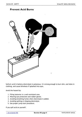
Section 05 - SAFETY Group 05: Safety Information Section 05 page 4 <- Go to Section TOC TM4756-REPAIR MANUAL
Service Cooling System Safely
Section 05 - SAFETY Group 05: Safety Information Section 05 page 6 <- Go to Section TOC TM4756-REPAIR MANUAL
Explosive release of fluids from pressurized cooling system can cause serious burns.
Shut off engine. Only remove filler cap when cool enough to touch with bare hands. Slowly loosen cap to first stop to relieve pressure before removing completely.
Remove Paint Before Welding or Heating
Avoid potentially toxic fumes and dust.

Hazardous fumes can be generated when paint is heated by welding, soldering, or using a torch.

Remove paint before heating:
Remove paint a minimum of 100 mm (4 in.) from area to be affected by heating. If paint cannot be removed, wear an approved respirator before heating or welding.
Section 05 - SAFETY Group 05: Safety Information Section 05 page 7 <- Go to Section TOC TM4756-REPAIR MANUAL
If you sand or grind paint, avoid breathing the dust. Wear an approved respirator. If you use solvent or paint stripper, remove stripper with soap and water before welding. Remove solvent or paint stripper containers and other flammable material from area. Allow fumes to disperse at least 15 minutes before welding or heating.
Do not use a chlorinated solvent in areas where welding will take place.
Do all work in an area that is well ventilated to carry toxic fumes and dust away.
Dispose of paint and solvent properly.
Avoid Heating Near Pressurized Fluid Lines
Flammable spray can be generated by heating near pressurized fluid lines, resulting in severe burns to yourself and bystanders. Do not heat by welding, soldering, or using a torch near pressurized fluid lines or other flammable materials. Pressurized lines can accidentally burst when heat goes beyond the immediate flame area.
Work In Ventilated Area

Section 05 - SAFETY Group 05: Safety Information Section 05 page 8 <- Go to Section TOC TM4756-REPAIR MANUAL
Engine exhaust fumes can cause sickness or death. If it is necessary to run an engine in an enclosed area, remove the exhaust fumes from the area with an exhaust pipe extension.
If you do not have an exhaust pipe extension, open the doors and get outside air into the area.
Wear Protective Clothing
Wear close fitting clothing and safety equipment appropriate to the job.

Section 05 - SAFETY Group 05: Safety Information Section 05 page 9 <- Go to Section TOC TM4756-REPAIR MANUAL
Prolonged exposure to loud noise can cause impairment or loss of hearing.

Wear a suitable hearing protective device such as earmuffs or earplugs to protect against objectionable or uncomfortable loud noises.
Operating equipment safely requires the full attention of the operator. Do not wear radio or music headphones while operating machine.
Practice Safe Maintenance
Understand service procedure before doing work. Keep area clean and dry.
Never lubricate, service, or adjust machine while it is moving. Keep hands, feet , and clothing from power-driven parts. Disengage all power and operate controls to relieve pressure. Lower
Section 05 - SAFETY Group 05: Safety Information Section 05 page 10 <- Go to Section TOC TM4756-REPAIR MANUAL
equipment to the ground. Stop the engine. Remove the key. Allow machine to cool.

Securely support any machine elements that must be raised for service work. Keep all parts in good condition and properly installed. Fix damage immediately. Replace worn or broken parts. Remove any buildup of grease, oil, or debris.
On self-propelled equipment, disconnect battery ground cable (-) before making adjustments on electrical systems or welding on machine.
On towed implements, disconnect wiring harnesses from tractor before servicing electrical system components or welding on machine.
Park Machine Safely
Before working on the machine:
Lower all equipment to the ground. Stop the engine and remove the key. Disconnect the battery ground strap. Hang a "DO NOT OPERATE" tag in operator station.
Use Proper Lifting Equipment
Section 05 - SAFETY Group 05: Safety Information Section 05 page 11 <- Go to Section TOC TM4756-REPAIR MANUAL
Lifting heavy components incorrectly can cause severe injury or machine damage. Follow recommended procedure for removal and installation of components in the manual.
Construct Dealer-Made Tools Safely

Faulty or broken tools can result in serious injury. When constructing tools, use proper, quality materials, and good workmanship.
Do not weld tools unless you have the proper equipment and experience to perform the job.
Support Machine Properly

Section 05 - SAFETY Group 05: Safety Information Section 05 page 12 <- Go to Section TOC TM4756-REPAIR MANUAL
Always lower the attachment or implement to the ground before you work on the machine. If the work requires that the machine or attachment be lifted, provide secure support for them. If left in a raised position, hydraulically supported devices can settle or leak down.
Do not support the machine on cinder blocks, hollow tiles, or props that may crumble under continuous load. Do not work under a machine that is supported solely by a jack. Follow recommended procedures in this manual.


When implements or attachments are used with a machine, always follow safety precautions listed in the implement or attachment operator′s manual.
Work in Clean Area
Before starting a job: Clean work area and machine.
Section 05 - SAFETY Group 05: Safety Information Section 05 page 13 <- Go to Section TOC TM4756-REPAIR MANUAL
Make sure you have all necessary tools to do your job. Have the right parts on hand.

Read all instructions thoroughly; do not attempt shortcuts.
Illuminate Work Area Safely
Illuminate your work area adequately but safely. Use a portable safety light for working inside or under the machine. Make sure the bulb is enclosed by a wire cage. The hot filament of an accidentally broken bulb can ignite spilled fuel or oil.
Service Machines Safely
Tie long hair behind your head. Do not wear a necktie, scarf, loose clothing, or necklace when you work near machine tools or moving parts. If these items were to get caught, severe injury could result.

Section 05 - SAFETY Group 05: Safety Information Section 05 page 14 <- Go to Section TOC TM4756-REPAIR MANUAL
Remove rings and other jewelry to prevent electrical shorts and entanglement in moving parts.
Use Proper Tools
Use tools appropriate to the work. Makeshift tools and procedures can create safety hazards. Use power tools only to loosen threaded parts and fasteners. For loosening and tightening hardware, use the correct size tools. DO NOT use U.S. measurement tools on metric fasteners. Avoid bodily injury caused by slipping wrenches. Use only service parts meeting John Deere specifications.

Service Tires Safely
Section 05 - SAFETY Group 05: Safety Information Section 05 page 15 <- Go to Section TOC TM4756-REPAIR MANUAL
Explosive separation of a tire and rim parts can cause serious injury or death.
Do not attempt to mount a tire unless you have the proper equipment and experience to perform the job.

Always maintain the correct tire pressure. Do not inflate the tires above the recommended pressure. Never weld or heat a wheel and tire assembly. The heat can cause an increase in air pressure resulting in a tire explosion. Welding can structurally weaken or deform the wheel.
When inflating tires, use a clip-on chuck and extension hose long enough to allow you to stand to one side and NOT in front of or over the tire assembly. Use a safety cage if available. Check wheels for low pressure, cuts, bubbles, damaged rims or missing lug bolts and nuts.
Section 05 - SAFETY Group 05: Safety Information Section 05 page 16 <- Go to Section TOC TM4756-REPAIR MANUAL
Service Front-Wheel Drive Tractor Safely
When servicing front-wheel drive tractor with the rear wheels supported off the ground and rotating wheels by engine power, always support front wheels in a similar manner. Loss of electrical power or transmission/ hydraulic system pressure will engage the front driving wheels, pulling the rear wheels off the support if front wheels are not raised. Under these conditions, front drive wheels can engage even with switch in disengaged position.
Safety Information - Air Brake System

Section 05 - SAFETY Group 05: Safety Information Section 05 page 17 <- Go to Section TOC TM4756-REPAIR MANUAL
CAUTION:
Compressed air tank is pressurized!
Always relieve pressure before working on the air brake system. Do not carry out any welding jobs on the air brake system.
Avoid Eye Contact With Radar

Section 05 - SAFETY Group 05: Safety Information Section 05 page 18 <- Go to Section TOC TM4756-REPAIR MANUAL
Radar ground speed sensor emits a very low intensity microwave signal. It will not cause any ill effects during normal use. Although intensity is low, DO NOT look directly into face of sensor while in operation, to avoid any possible eye damage.

Keep ROPS Installed Properly
Make certain all parts are reinstalled correctly if the roll-over protective structure (ROPS) is loosened or removed for any reason. Tighten mounting bolts to proper torque.
The protection offered by ROPS will be impaired if ROPS is subjected to structural damage, is involved in an overturn incident, or is in any way altered by welding, bending, drilling, or cutting. A damaged ROPS should be replaced, not reused.

Section 05 - SAFETY Group 05: Safety Information Section 05 page 19 <- Go to Section TOC TM4756-REPAIR MANUAL
Replace Safety Signs
Replace missing or damaged safety signs. See the machine operator’s manual for correct safety sign placement.

Dispose of Waste Properly
Improperly disposing of waste can threaten the environment and ecology. Potentially harmful waste used with John Deere equipment include such items as oil, fuel, coolant, brake fluid, filters, and batteries.

Use leakproof containers when draining fluids. Do not use food or beverage containers that may mislead someone into drinking from them.
Do not pour waste onto the ground, down a drain, or into any water source.
Section 05 - SAFETY Group 05: Safety Information Section 05 page 20 <- Go to Section TOC TM4756-REPAIR MANUAL
Air conditioning refrigerants escaping into the air can damage the Earth’s atmosphere. Government regulations may require a certified air conditioning service center to recover and recycle used air conditioning refrigerants.
Inquire on the proper way to recycle or dispose of waste from your local environmental or recycling center, or from your John Deere dealer.
Live With Safety
Before returning machine to customer, make sure machine is functioning properly, especially the safety systems. Install all guards and shields.

Safety Measures on Electronic Control Units
Section 05 - SAFETY Group 05: Safety Information Section 05 page 21 <- Go to Section TOC TM4756-REPAIR MANUAL
CAUTION:
Before installing test equipment on tractor, always shut off the engine and turn off key switch.
CAUTION:
Always engage the park lock when performing tests with the engine running.
CAUTION:
When testing is performed with the engine running, there is a risk of injury from rotating parts.
IMPORTANT:
Do not use a test lamp on any control unit. Only use a multimeter (JT05791A/JDG1478).
IMPORTANT:
To protect electronic circuits, disconnect the battery and alternator before performing any welding on the tractor.
GENERAL INFORMATION (g) by Belgreen Section 05 page 22 <- Go to Section TOC TM4756-REPAIR MANUAL
Section 10 - GENERAL INFORMATION
TM4756-REPAIR MANUAL (g) by Belgreen <- Go to Global Table of contents TM4756-REPAIR MANUAL
Table of contents Group 05 - Specifications ....................................................................................1 Specifications (Summary of References) ................................................................1 Engine Specifications 3 Cooling System ..............................................................................................3 Injection Pump (Bosch VP44) ..............................................................................4 Level 11 Electronic Fuel System with HPCR (Denso) ...................................................4 Air Intake System Electrical system . ........................................................................................4 . .........................................................................................4 Hydrostatic Steering System 4 AutoTrac......................................................................................................4 Clutch.........................................................................................................4 AutoPowr/IVT transmission ................................................................................4 PowrQuad Plus transmission ...............................................................................5 AutoQuad II transmission...................................................................................5 Creeper transmission.......................................................................................5 Rear PTO Front PTO . ..................................................................................................5 ...................................................................................................5 Differential assembly.......................................................................................6 Differential lock .............................................................................................6 Final drives ...................................................................................................6 Front-Wheel Drive FWD Axle with TLS 6 ........................................................................................6 Cab Suspension: Hydraulic Brakes ...........................................................................................6 6 Handbrake...................................................................................................6 Parking Lock.................................................................................................6 Hydraulic System with Axial Piston Pump (PFC System)...............................................6 Rockshaft Front Hitch ...................................................................................................7 . ................................................................................................7 Ground Speeds ..............................................................................................7 Front and Rear Wheels .....................................................................................7 Dimensions and Weights ..................................................................................7 Capacities ...................................................................................................8 Handling and Storing Diesel Fuel .........................................................................9 Diesel Fuel................................................................................................. 11 Lubricity of Diesel Fuel 11 Diesel Engine Break-In Oil ............................................................................... 13 Diesel Engine Oil (Engine Serial Number up to 799999) Diesel Engine Oil (Engine Serial Number from 800000) .......................................... 15 ........................................... 17 Transmission and Hydraulic Oil ......................................................................... 19 Front-Wheel Drive Axle Oil .............................................................................. 21 Diesel Engine Coolant .................................................................................... 23 Supplemental Coolant Additives ........................................................................ 24 Grease...................................................................................................... 24 Oil Filters................................................................................................... 25 Mixing of Lubricants ...................................................................................... 26
TM4756-REPAIR MANUAL (g) by Belgreen <- Go to Global Table of contents TM4756-REPAIR MANUAL Lubricant Storage......................................................................................... 26 Operating in Warm Temperature Climates............................................................ 26 Alternative and Synthetic Lubricants................................................................... 27 Unified Inch Bolt and Screw Torque Values............................................................ 28 Metric Bolt and Screw Torque Values Hydraulic system inch fitting torques . ............................................................... 29 ................................................................ 30 Hydraulic system metric fitting torques ............................................................... 31 Product identification and component serial numbers............................................... 32 Engine Serial Number .................................................................................... 34 Transmission serial number ............................................................................. 34 Front wheel drive axle serial number................................................................... 35 Operator′s cab serial number Operator′s seat serial number Sub-assembly serial numbers . ........................................................................ 35 ......................................................................... 36 37 Group 10 - Tune-Up ......................................................................................... 38 Tune-Up (Summary of References)..................................................................... 38 Specifications ............................................................................................. 39 Using High-Pressure Washers ........................................................................... 39 Preliminary Engine Test.................................................................................. 40 Tractor Tune-Up ........................................................................................... 41 Removing and Cleaning the Primary Air Cleaner Element .......................................... 43 Checking the Air Cleaner Safety Element ............................................................. 43 Installing the Primary Filter Element ................................................................... 44 Checking the Air Intake System Connections for Leaks 44 Checking the Crankcase Vent Hose for Clogging ..................................................... 45 Cleaning Dirt from Radiator Screen Keeping the Radiator Screen Clean .................................................................. 45 . ................................................................. 46 Checking the Caps on the Expansion Tank............................................................ 46 Checking the Radiator for Leaks ........................................................................ 47 Checking the engine′s thermostat ...................................................................... 47 Checking the Fuel Transfer Pump Operation.......................................................... 47 Bleeding the fuel system (with Bosch VP44 injection pump) ....................................... 49 Checking the fuel filter (with Bosch VP44 injection pump).......................................... 52 Cleaning the water trap.................................................................................. 52 Checking the Fuel Filter (with Denso/Stanadyne Injection Pump; Stage II Engines According to 97/68/EC)............................................................................................. 54 Bleeding the Fuel System (with Stanadyne Injection Pump; Stage II Engines According to 97/68/EC)............................................................................................. 55 Bleeding the Fuel System (with Denso Injection Pump; Stage II Engines According to 97/68/EC)............................................................................................. 55 Run Engine until it is Warm and Check Engine Speeds .............................................. 56 Checking Setting of Fuel Injection Pump............................................................... 56 Cleaning the Battery, Cables and Battery Box with a Clean Cloth ................................. 56 Check the Neutral Start Circuit ......................................................................... 58 Checking operation of starter motor ................................................................... 60 Checking the lighting circuit ............................................................................ 60 Final Engine Check........................................................................................ 61 Tractor Operation Check ................................................................................. 61 Group 15 - Predelivery Inspection ....................................................................... 63 Predelivery Inspection .................................................................................... 63
Group 05 - Specifications Specifications (Summary of References)
”Engine specifications”
”Cooling system”
”Bosch VP44 injection pump”
”Level 11 electronic fuel system with HPCR (Denso)”
”Air intake system”
”Electrical system”
”Hydrostatic steering”
”AutoTrac”
”Clutch”
”AutoPowr/IVT transmission”
”PowrQuad Plus transmission”
”AutoQuad II transmission”
”Creeper transmission”
”Rear PTO”
”Front PTO”
”Differential”
”Differential lock”
”Final drives”
”Front-wheel drive”
”Front-wheel drive axle with TLS”
”Cab suspension”
”Hydraulic brakes”
”Handbrake”
”Park lock”
”Hydraulic system with axial piston pump”
”Hitch”
”Front hitch”
”Ground speeds”
”Front and rear wheels”
”Dimensions and weights”
”Capacities”
”Handling and storing diesel fuel”
”Diesel fuel”
”Lubricity of diesel fuel”
”Diesel engine break-in oil”
”Diesel engine oil (engine serial number up to 799.999)”
”Diesel engine oil (engine serial number from 800.000)”
”Transmission and hydraulic oil”
”Front-wheel drive axle oil”
”Diesel engine coolant”
”Coolant additives”
”Grease”
Section 10 page 1 <- Go to Section TOC TM4756-REPAIR MANUAL Section 10 - GENERAL INFORMATION Group 05: Specifications