Workshop Manual EK10

1Vehicle data
2Travel motor
5Brake
Electromagnetic spring brake..................................................5-01
Checking the rotor...........................................................5-03
Adjusting the brake clearance.........................................5-04 General...................................................................5-04
Adjustment process................................................5-04
Adjusting the braking force..............................................5-05 Maintenance....................................................................5-06
Measuring the brake deceleration...........................................5-07
General...........................................................................5-07
Preparations for measurement........................................5-07
Evaluating the measurement..........................................5-08
6Idling wheels General....................................................................................6-01
7Hydraulic Montagevorschrift....................................................................7-01 Hydraulic circuit plan...............................................................7-01
Block diagram for NO/HO........................................................7-02
Block diagram for NM/HM.......................................................7-03
Pump unit................................................................................7-04
General...........................................................................7-04
Components:...................................................................7-04
Electrically releasable non-return valve..........................7-05
Replacing the carbon brushes (NO, NM)........................7-06
Replacing the carbon brushes (HO, HM)........................7-07
Removal..........................................................................7-08
Removing the pump motor (NO, NM).............................7-09
Removing the pump motor (HO, HM).............................7-10
Adjustment Pressure release valve.................................7-11
Changing the hydraulic oil...............................................7-12
Bleeding the lift cylinders and the hydraulic system................7-13
Procedure........................................................................7-13
Distributor block.......................................................................7-14
Bubble reservoir......................................................................7-15
Hydraulic hoses.......................................................................7-16
13Vehicle
15End-of-aisle
16Speed sensor
17ABÜ - Braking monitor
18Travel control
21Travel control software
General..................................................................................21-01
Making a connection..............................................................21-01
Setting parameters................................................................21-02
Test........................................................................................21-03
Diagnosis...............................................................................21-03
"File" menu............................................................................21-03
Summary of the most important parameters.........................21-05
Battery discharge curves.......................................................21-06
List of parameters..................................................................21-07
Description of parameters.....................................................21-12
Errors displayed with flashing code.......................................21-17
List of error codes..................................................................21-18
Tester Table...........................................................................21-19
22Steering software
General..................................................................................22-01 Making a connection..............................................................22-02 Errors.....................................................................................22-03 Current errors................................................................22-03
Setpoint potentiometer..................................................22-05 Actual value potentiometer............................................22-06 Tester.....................................................................................22-09 Speed measurement.....................................................22-09
Amplifier data................................................................22-10
Digital inputs and outputs..............................................22-11 Travel on curves active.........................................22-11 Deadman..............................................................22-11
Steering wheel/ -knob...........................................22-11
Steering OK..........................................................22-11
Steering motor contactor......................................22-12
Safety relay...........................................................22-12
Potentiometer voltages.................................................22-13
Supply voltage of actual and setpoint values.......22-13
Setpoint voltage at the steering wheel..................22-13
Actual value voltages at the drive wheel..............22-13
Table of errors........................................................................22-14
Table of Contents
23Hand-held programming unit
General..................................................................................23-01
Operating elements...............................................................23-01
Switching on..........................................................................23-02
Switching off..........................................................................23-02
Language selection...............................................................23-03
Setting parameters................................................................23-04 PROGRAM menu.........................................................23-04
Function........................................................................23-05
Special program menu..........................................................23-06
Resetting to initial settings............................................23-07
Loading settings from the control system into the programming unit.............................................23-08
Loading settings from the programming unit into the control system..................................................23-09
Deleting the diagnosis data...........................................23-10
Adjusting the display contrast.......................................23-11 Language selection.......................................................23-12
Displaying information about the programming unit......23-12
Displaying information about the control.......................23-12 Test menu..............................................................................23-13 Displaying current errors.......................................................23-14 Error history...........................................................................23-14
fuels and lubricants.........................................99-02
Functional check of the deadman brake........................99-03
Functional check of the neutral brake............................99-03
Functional check of the reversing brake........................99-03
Maximum wear on the brake lining................................99-03
the lifting chains for damage..........................99-09
the chain elongation.......................................99-13 Main lift..................................................................99-13
the chain elongation.......................................99-14
lift..........................................................99-14
the lifting chains............................................99-15 Repairing the lifting chains.............................................99-15 Lubricating the lifting chains...........................................99-16 Cleaning the chains........................................................99-17
Definition of vehicle model names
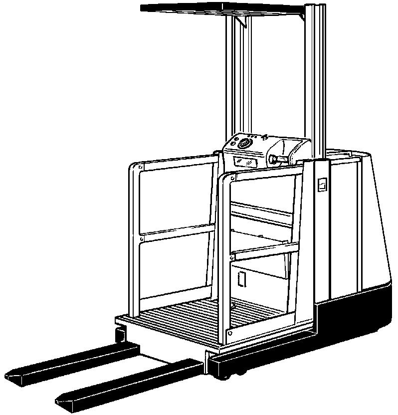
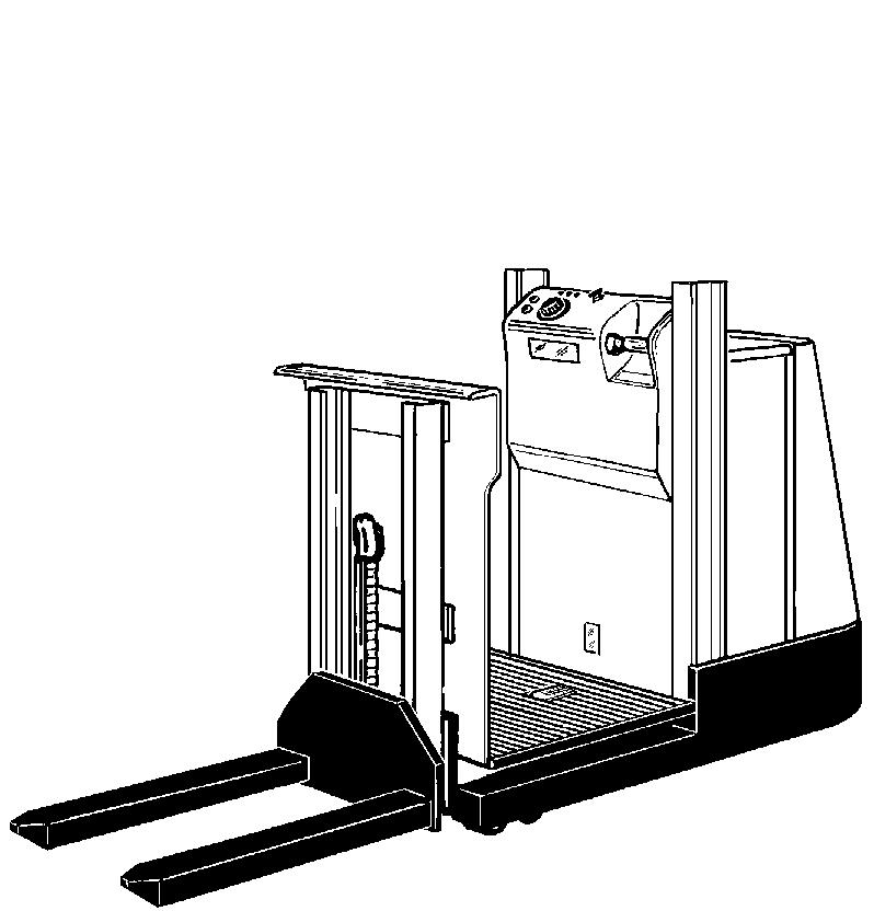
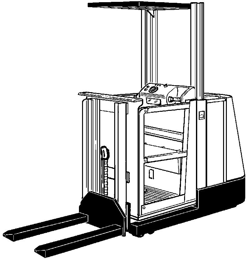
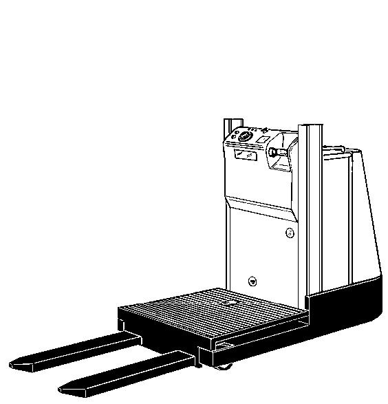
EK10 NO (Niederhub ohne Zusatzhub = low lift without additional lift)
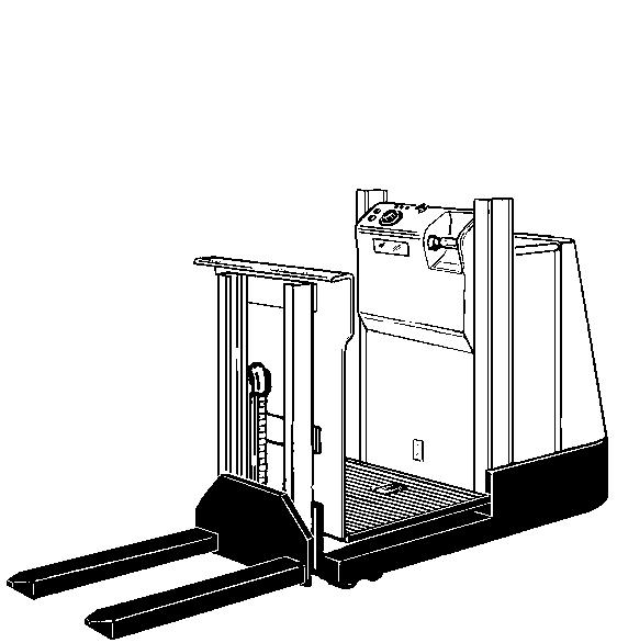
EK10 NM (Niederhub mit Zusatzhub = low lift with additional lift)
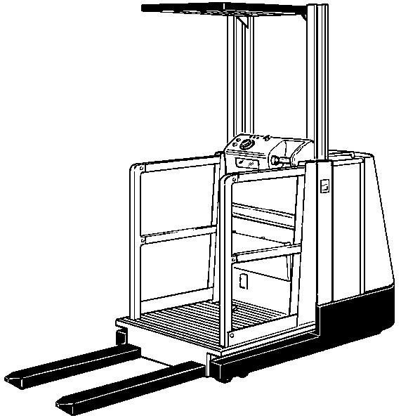
EK10 HO (Hochhub ohne Zusatzhub = high lift without additional lift)
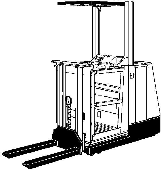
EK10 HM (Hochhub mit Zusatzhub) = high lift with additional lift)
Signs on the vehicle
Nameplate


Travel speed
Outside the aisle
•Type NOalwaysvmax = 9.0km/h
•Type NMPlatform level < 0.5mvmax = 9.0km/h
•Type NMPlatform level > 0.5m & steering straight-onvmax = 4.0km/h
•Type NMPlatform level > 0.5m & steering > ±10°vmax = 2.5km/h
•Type HOPlatform level < 1.2mvmax = 9.0km/h
•Type HOPlatform level > 1.2m & steering straight-onvmax = 4.0km/h
•Type HOPlatform level > 1.2m & steering > ±10°vmax = 2.5km/h
•Type HMPlatform level < 0.5mvmax = 9.0km/h
•Type HMPlatform level > 0.5m & steering straight-onvmax = 4.0km/h
•Type HMPlatform level > 0.5m & steering > ±10°vmax = 2.5km/h
Inside the aisle
Always vmax = 9,0km/h
General
The drive motor used in this vehicle is a 24V shunt motor.
The armature and field coils are controlled separately by the travel controller.
The travel movement is initiated as follows: voltage is applied to the armature and the field is excited. As soon as the armature voltage is equal to the battery voltage, the field current is reduced in order to achieve an increase in speed.
The current speed of the drive motor is determined by a current measurement (measuring shunt) in the travel controller.
Temperature monitor
The drive motor has a temperature monitor (field coil resistor at normal temperature approx. 1.8 ). If the temperature is >90°C, deceleration is initiated by the MOT WRM parameter. If the temperature rises above 105°C, a traction cut-out is initiated by the Mot Hot parameter (see Software travel controle).


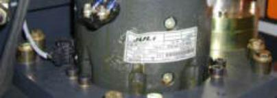
Technical data
Model designationGF 114 - F4
Id. no.W8 408 250
Excitation typeshunt wound
Voltage24V
Rated output2000W
Rated speed2700 rpm
Direction of rotationright / left
Protection / insulation classJP 00 / 20
Field excitation6V / 9A
Armature current104A
On-period
Terminals
S2 = 60min
A 1 Armature winding start
A 2 Armature winding end
F1Field winding
F2Field winding
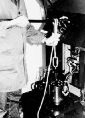
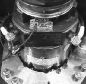
Removing the travel motor
Because the brake (2) is mounted on the travel motor, the vehicle is no longer braked once the brake and the travel motor have been removed. For this reason, always secure the vehicle to prevent it rolling away!
Pull out the battery plug.
Remove power leads (3.
Unplug speed sensor (9).
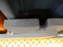
Remove electro magnetic break (2)
The connection point for the connection cable of the spring brake may be in the cable duct (4)!
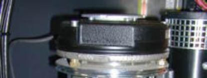
Remove the 8 screws (5).
Screw the special eyebolt tool M6 (6), into the armature shaft (min. 20mm).
Pull the rope (7) (special tool: pulley) through the eyebolt (6).
Ensure that the rope is pulled through correctly (8).
Set the length (holding it tight with your hand is sufficient).
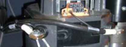
Lift the travel motor out with a lever rod.
Never work without the correct aids. A considerable amount of force is required to release the seal (1) between the travel motor and the gear.
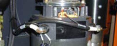
Remove the aids.
Lift the travel motor out by hand.
When the travel motor has been removed, the opening left in the gear (2) must be closed off immediately, in order to prevent oil entering the inside of the gear.


Installation
To install the travel motor, follow the instructions for removal in reverse order. It can be installed without the use of any special tools.
Only use screws of the prescribed length, otherwise the four-point bearing may be damaged!
Screw in and tighten the 8 screws (3) diagonally in several passes.
