SM VOLVO L90C WHEEL LOADER Service Repair Manual -
DOWNLOAD
Document Title:
Description Function Group: 500
Profile: L90C
Description
Service brakes
Service Information
Information Type: Service Information Date: 2014/5/22
The machine is provided with an all-hydraulically controlled brake system divided into two circuits, where one circuit acts on the front axle brakes and the other circuit on the rear axle brakes.
Both the front and rear axles are provided with wet disc brakes.
The system also consists of an hydraulic oil pump, a brake valve and accumulators.
The hydraulic oil pump serves both the brake and the servo systems and is mounted in tandem with the steering pump. The oil is drawn from the hydraulic oil tank.
Each circuit has its own accumulator. These are precharged with nitrogen gas and their purpose is to store energy and to safeguard braking capacity with a good margin.
If the pressure in the accumulator circuit for some reason drops below 9 MPa (1305 psi) this will be indicated by the brake system warning lamp lighting up and the central warning will come into action and if the gear selector is moved to the forward or reverse drive positions the buzzer will sound. If the machine is equipped with a display unit (optional equipment),
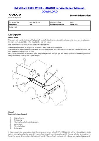
Figure 1
Brakes (principle diagram)
1. Hydraulic tank 2. Brake pump 3.
SM VOLVO L90C WHEEL LOADER Service Repair Manual -
DOWNLOAD
this will also show a warning of low brake pressure.
Instrument panel
1. Warning lamp, low brake pressure (LC6)
2. Central warning (LC9)
Brake valve
The brake valve includes control valve, unloading valve and foot brake valve
The purpose of the control valve is to divide the oil flow from the pump to the brake system and the servo system.
The purpose of the unloading valve is to distribute the oil flow to the different brake circuits and control the pressure in the system.
The foot brake valve is divided into two circuits, where one of the circuits acts on the front axle brakes and the other on the rear axle brakes.
2. Pressure outlet for checking output brake pressure to circuit
SM VOLVO L90C WHEEL LOADER Service Repair Manual -
DOWNLOAD
7. Accumulator for hydraulic parking brake (S3)
L90C Serial No. –15289 (EU), –62960 (US), –70176 (Brazil)
L120C Serial No. –12376 (EU), –62083 (US), –70172 (Brazil)
8. Adjusting screw, unloading pressure
9. Accumulator, front circuit (S2)
10. Pressure sensor, stop lights (SE29)
SM VOLVO L90C WHEEL LOADER Service Repair Manual -
DOWNLOAD
Document Title: Function Function Group: 500
Profile: L90C
Function
Charging, brake in resting position
Service Information
Information Type: Service Information Date: 2014/5/22
When the engine has stated, the oil flow from pump (1) enters the brake valve through connection P.
The oil flow from the pump is greater than the amount restriction (2) will let through. This will cause piston (3) in the control valve to begin to open and oil is supplied to the servo system via the connection marked N.
All oil to the brake system passes through restriction (2). If the system pressure is below 12 MPa (1740 psi), unloading spool (4) will be in its upper position. The oil is supplied to the unloading spool via duct (5). From there the oil is conducted to the control valve and in at the back of piston (3). The oil is also conducted through the duct in the unloading spool to the top of the spool.
From restriction (2) the oil also flows through non-return valve (6). Through duct (7) the oil is conducted out to the parking brake circuit. Non-return valve (9) lets the oil flow through to accumulator (11) at the connection marked S1 and via a duct on to spool (13) in the foot brake valve.
Non-return valve (10) lets the oil flow through to accumulator (12) at the connection marked S2 and via a duct on to spool (14) in the foot brake valve.
When the pressure has risen to the accumulator precharging pressure, approx. 5 MPa (725 psi), the nitrogen gas will be compressed by the flowing into the accumulators at the same time as the pressure in the system rises.
During the charging stage the pressure is the same on both sides of piston (15). The system pressure acts directly on unloading spool (4) and works against spring (16).
Figure 1 Charging
SM VOLVO L90C WHEEL LOADER Service Repair ManualDOWNLOAD
A To hydraulic parking brake (optional equipment L90C, standard equipment L120C)
N To the servo system
Orange = Servo pressure
Pink = Build-up of pressure
Green = Return pressure
Unloading, brake in resting position
When the accumulators (one for each brake circuit) fill up with oil, the pressure in the system rises at the same time towards the max. pressure, 15.5 MPa (2248 psi). The oil which exerts pressure on unloading spool (4) overcomes the force of spring (16) and the spool is displaced downward. The space above unloading spool (4) will then have a return connection to tank. The spool will be kept in the lower position by the system pressure which acts on piston (15). The "active" area of the piston is slightly larger than the corresponding area on the spool. The space behind piston (3) in the control valve will also have a return connection to tank. The pressure required to keep the valve open is reduced. This means non-return valve (6) will be closed by the system pressure.
In this situation the entire oil flow from pump (1) passes piston (3) and moves on to the servo system.
When the brakes are used and the accumulated pressure drops to approx. 12 MPa (1740 psi), unloading spool (4) will be displaced upward because of the spring force.
The return connection to tank through unloading spool (4) will be closed and the oil will be conducted to the underside of piston (3) in the control valve. This will cause the pressure at the top of the piston to rise and the pump flow will be charging the brake system via non-return valve (6). The difference between the unloading pressure and the cut-in pressure is determined by the area difference on piston (15) and unloading spool (4).
Brake in resting position (not actuated)
When the foot brake valve is not actuated, return springs (19 and 20) are pressing spools (13 and 14) upward.
Pressure ducts (21 and 22) will then be closed and the brake connections marked B1 and B2 will be connected to tank from the connection marked T via ducts in the valve housing, see [Invalid linktarget] .
SM VOLVO L90C WHEEL LOADER Service Repair Manual -
SM VOLVO L90C WHEEL LOADER Service Repair Manual -
DOWNLOAD
Red = System pressure
Green = Return pressure
Partial brake application
If the brake pedal is partially depressed, spring (23) will be pretensioned. Spools (13 and 14) will then be displaced downward, closing the tank connection from the brakes and oil from pressure ducts (21 and 22) can flow out to the brakes via the connections marked B1 and B2. This causes the brakes to be applied and the pressure at connections B1 and B2 to rise.
When this pressure corresponds to the force at which spring (23) has been pretensioned, the pressure will aid return spring (19) in pushing up spool (13) and spring (20) in pushing up spool (14). In this way the oil flow to the brakes is closed and a brake application corresponding to the depression of the brake pedal is obtained.
Full brake application
The downward movement of the foot brake pedal is limited by the foot brake pedal adjusting screw, see [Invalid linktarget] . When the pedal is depressed to the end position, the valve still takes up a partial brake application position and the pressure out to the brakes is limited to approx. 8 MPa (1160 psi).
Figure 3
1. Adjusting screw for output brake pressure
2. Security seal
SM VOLVO L90C WHEEL LOADER Service Repair Manual -
SM VOLVO L90C WHEEL LOADER Service Repair Manual
DOWNLOAD
Orange = Servo pressure
Pink = Partial pressure
Red = System pressure
Green = Return pressure
SM VOLVO L90C WHEEL LOADER Service Repair Manual -
Document Title: Hydraulic diagram
Profile:
Hydraulic diagram
L90C
Function Group: 500
DOWNLOAD
Service Information
Information Type: Service Information Date: 2014/5/22
Exercise cleanliness when working with the brakes.
1. Start the engine and charge the accumulators. Raise the lifting arms. Secure the lifting arms with support 999 3831, see [Invalid linktarget] Stop the engine and apply the brake.
1
1. 999 3831 Support
CAUTION
The brake must be applied during the entire wear check.
2. Remove the plug from the wear indicator, see [Invalid linktarget]