

DOWNLOAD SERVICE MANUAL

T8010 [Z8Rx06001 - ]
T8020 [Z8Rx06001 - ]
T8030 [Z8Rx06001 - ]
T8040 [Z8Rx06001 - ]
T8050 [Z8Rx06001 - ]

Hydraulic fluid escaping under pressure can have enough force to penetrate the skin. Hydraulic fluid may also infect a minor cut or opening in the skin. If injured by escaping fluid, see a doctor at once. Serious infection or reaction can result if medical treatment is not given immediately. Make sure all connections are tight and that hoses and lines are in good condition before applying pressure to the system. Relieve all pressure before disconnecting the lines or performing other work on the hydraulic system. To find a leak under pressure use a small piece of cardboard or wood. Never use hands. Failure to comply could result in death or serious injury.
When removing hardened pins such as a pivot pin, or a hardened shaft, use a soft head (brass or bronze) hammer or use a driver made from brass or bronze and a steel head hammer.
When using a hammer to remove and install pivot pins or separate parts using compressed air or using a grinder, wear eye protection that completely encloses the eyes (approved goggles or other approved eye protectors).
Use suitable floor (service) jacks or chain hoist to raise wheels or tracks off the floor. Always block machine in placed with suitable safety stands.
When servicing or repairing the machine. Keep the shop floor and operators compartment and steps free of oil, water, grease, tools, etc. Use an oil absorbing material and or shop cloths as required. Use safe practices at all times.
Batteries contain acid and explosive gas. Explosions can result from sparks, flames or wrong cable connections. To connect the jumper cables correctly to the battery of this machine see the Operators Manual. Failure to follow these instructions can cause serious injury or death.
Hydraulic pump - Dynamic description
T8010, T8020, T8030, T8040, T8050
The tractor uses three hydraulic pumps which are driven through a drive housing on the right side of the range transmission. The pump drive housing gears are driven by the PTO drive line and all the pumps turn at approximately 1.33 times engine speed. A PFC (pressure and flow compensating) piston pump is attached to the front of the pump drive housing, while the tandem gear pumps are attached to the rear of the pump drive housing.
The front section of the tandem gear pump supplies the regulated pressure circuit: brake valve, transmission control valves, PTO and differential lock valve, auxiliary and hitch valve pilot circuits. The rear section supplies charge flow to the PFC pump(s). The PFC pump supplies flow to the priority valve, which directs flow to the steering system, remote valves and the three point hitch.
All hydraulic lines are equipped with O-ring face seals to ensure reliable, vibration-resistant connections.
Charge/lubrication pump
The charge/lubrication pump is the rear section of the dual gear pump and it is used to supply the main PFC pump with a charged inlet condition to prevent cavitation. The pump also supplies lubrication and cooling requirements for the transmission.
The pump draws oil from the transmission housing through a 100 mesh suction screen. The pump flow is directed across the main filter assembly to provide clean charge and lubrication oil.
The pump flow rate at rated speed 2667 RPM( 2000 RPM engine speed) is 177.0 l/min (47.0 US gpm).
Regulated circuit pump
The regulated circuit pump is the front section of the tandem gear pump. The pump draws oil from the system reservoir through a 100 mesh suction screen. The pump flow passes through the regulated circuit filter housing and into the priority regulator valve. The priority regulator valve maintains the regulated pressure circuit at 22.4 - 24.5 bar (325 - 355 psi). The regulated pump flow supplies the PTO/differential lock valve, transmission control valves and brake valve. The remote and hitch valves are also supplied with regulated pressure.
Once these circuits are satisfied, the excess regulated pump flow is directed through the oil coolers and joins up with the charge pump flow at the downstream side of the main filter head.
The pump flow rate at rated speed of 2667 RPM ( 2000 RPM engine speed) is 102.0 l/min (27.0 US gpm).
PFC piston pump
The axial piston pump has a variable flow output and can operate at variable pressures. The pump matches the hydraulic power output to the actual load requirements to ensure maximum efficiency and the minimum use of fuel.
The pump inlet is charged to prevent cavitation. The pump output flow is supplied to the priority regulator valve. The priority regulator valve gives top priority to the steering system and trailer brake circuit. Once the steering system and trailer brake circuits are satisfied the priority regulator valve supplies pump flow to the remote auxiliary valves and three point hitch valve.
The maximum pump flow rate for the standard pump at rated speed of 2667 RPM ( 2000 RPM engine speed) is 146.0 l/min (38.6 US gpm).
NOTE: The standard pump system delivers approximately 113.6 l/min (30.0 US gpm) through a single remote section. This is due to resistance created by oil flowing through restrictive passage ways and long lengths of tubing or hose.
Optional high flow PFC piston pump
An optional high flow PFC piston pump is available. The high flow rate maximum pump flow rate at rated speed of 2667 RPM ( 2000 RPM engine speed) is 220 l/min (58 US gpm).
NOTE: The high flow pump system delivers approximately 113.6 l/min (30.0 US gpm) through a single remote section. This is due to resistance created by oil flowing through restrictive passage ways and long lengths of tubing or
hose. However, when operating two or more remote sections the high flow pump has approximately 75.7 l/min (20.0 US gpm) more flow than a standard pump system to supply the additional remote circuits. RCPH07CCH026FAE 1

1. Charge/lubrication pump outlet (rear section) 3. High flow PFC piston pump
2. Regulated circuit pump outlet (front section) 4. Dual gear pump/regulated system filter housing
Optional Megaflow PFC piston pump
The axial piston pump has a variable flow output and can operate at variable pressures. The pump matches the hydraulic power output to the actual load requirements to ensure maximum efficiency and the minimum use of fuel. The maximum pump flow rate at rated speed 2667 RPM( 2000 RPM engine speed) is 117.0 l/min (31.0 US gpm).
The pump inlet is charged to prevent cavitation. The pump output flow is supplied directly to the remote auxiliary manifold. The manifold is equipped with internal plugs to separate the dual flow supply flow, signal line pressure and signal line pilot relief from the standard PFC piston pump circuit. The Megaflow pump supplies only the third, fourth or fifth remote sections. The two PFC pump hydraulic circuits operate independently.
NOTE: The Megaflow pump system delivers approximately 113.6 l/min (30.0 US gpm) through a single remote section. This is due to resistance created by oil flowing through restrictive passage ways and long lengths of tubing or hose.

1. Megaflow signal line
2. Megaflow outlet
3. Megaflow PFC pump
Lubrication circuit
RCPH07CCH027FAE 2
4. Standard PFC pump
5. Megaflow inlet
6. Main filter assembly
The lubrication flow is a combination of both dual gear pumps’ outputs – filtered charge pump flow and filtered/cooled excess regulated circuit flow. Inlet charge pressure and lubrication are limited to 5.0 bar (75 psi) by a lube relief valve.
The lubrication circuit provides a low pressure flow of oil to lubricate and cool the following transmission components: master clutch, bevel pinion gears, brakes, drop box, odd/even clutches, MFD/range, creep drive and PTO/differential lock lube.

1. Left brake lube
RCPH07CCH029FAE 3
6. Drop box lube
2. PTO lube supply 7. Right brake lube
3. Range lube 8. Charge pump to filter inlet
4. Master clutch lube 9. Oil cooler return to filter 5. Odd/even lube

RCPH07CCH021AAE 4
10. Lube relief hose
11. Drop box output lube (without creeper)
Regulated pressure circuits
12. Drop box rear bearing lube
The regulated circuit is supplied by the front dual gear pump. The pump flow passes through the regulated circuit filter housing and onto the priority regulator valve. The pressure regulator portion of the valve maintains the regulated pressure at 22.4 - 24.5 bar (325 - 355 psi).
The following components are supplied by the regulated circuit:
• speed transmission powershift valve,
• odd/even transmission powershift valve (includes creep and park brake),
84318454 14/03/2010 A.10.A / 96
• range transmission powershift valve (includes MFD),
• PTO/differential lock valve,
• master clutch inching valve,
• brake valve,
• hitch valve pilot pressure,
• remote valve pilot pressure
• and MFD clutch supply.
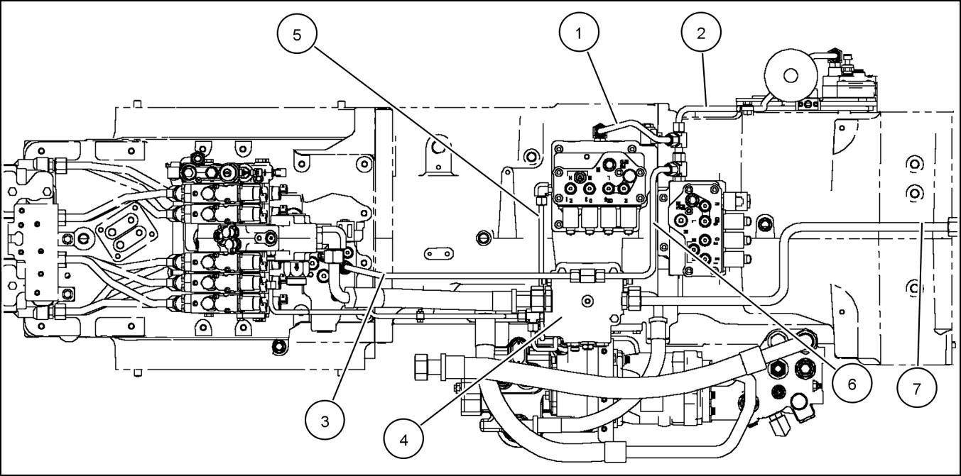
1. Range regulated supply tube
2. Speed transmission control valve regulated supply, upper tube
3. Priority regulator valve to PTO valve
4. Priority regulator valve
5. Master clutch diagnostic tube (See next view.)
6. Transmission control valve regulated supply
7. Priority regulator valve excess to oil coolers
NOTE: Brake, hitch and remote valves regulated supply tubes not shown.
RCPH07CCH023FAE 5


1. Master clutch diagnostic coupler
RCPH07CCH022FAE 6
RCPH07CCH028BAE 7
2. Regulated circuit accumulator
3. Speed transmission control valve regulated supply, lower tube
Tandem gear pump Charge and lubrication - Component identification
T8010, T8020, T8030, T8040, T8050
1

2
1. Pump assembly 5. Lube relief valve assembly
2. Priority regulator valve
3. Regulator section inlet
4. Regulated circuit filter
6. Pump inlet section
7. Suction screen shroud
RCPH07CCH021BAE
RCPH07CCH020BAE
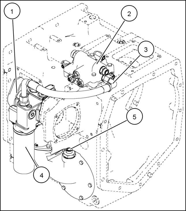
Motor return - Component identification
T8010, T8020, T8030, T8040, T8050
1. Case drain coupler
2. Motor return coupler
3. Motor return tube
RCPH07CCH034BAE 1

RCPH07CCH020AAE 2
Pump drive - Exploded view
T8010, T8020, T8030, T8040, T8050

1. Pump drive housing
2. Idler shaft
RCPH07CCH653FBC 1
7. Bearing cup
8. Bearing cone
3. Bearing 9. Driven gear
4. Spacer 10 Shim
5. Retaining ring
6. Idler gear
11. O-ring
12. Bearing cone
Control valve Priority/Regulator valve - Dynamic description
T8010, T8020, T8030, T8040, T8050
The priority/regulator valve assembly is located on the top right side of the range transmission. The assembly contains:
• the priority spool,
• the regulator spool,
• and steering relief valve.
The front section of the dual gear pump and the pressure and flow compensating (PFC) piston pump supply oil to the priority/regulator valve.
Priority spool ( supplied by the PFC piston pump)
Oil flows into the priority/regulator valve from the left side port (2) Steering has first priority: oil flows across the priority spool (11) and out the steering supply port (3) There is a cross-drilled passage near the top of the priority spool. Oil enters this orifice and starts to build pressure against the spring. As steering demand is satisfied, pressure builds on the top of the priority spool and the spool moves down against its spring, opening a passage to the remote and hitch circuits (13)
When the steering circuit is placed on demand, a pressure drop is created on the top end of the priority spool. Signal and spring pressure work against pump outlet pressure, and the priority spool moves up to accommodate steering demand.
Once steering demand is satisfied, pressure builds on the top of the priority spool and the spool shifts down to increase flow to the remote and hitch circuits. When equipped with trailer brakes, oil is also supplied from the priority valve to the trailer brakes.

4. Regulated supply to system
10. Steering signal to hand pump
5. Excess flow to coolers 11. Priority spool
6. Regulated supply to brakes 13. Supply to remote valves RCPH07CCH016GAE 2
1. Priority regulator valve 8. Regulated pressure adjustment
2. Supply from PFC piston pump 9. Steering relief adjustment
3. Supply to steering
4. Regulated supply to system
5. Excess flow to coolers
6. Regulated supply to brakes
7. Regulated supply
Steering signal to hand pump
Priority spool
Regulator spool
Supply to remote valves
Internal plug
Regulator spool (supplied by regulated pump section)
Regulated pump flow enters the priority/regulator valve at the right side port (7) Oil flows across the regulator spool (12) and supplies all the regulated circuits through the side port (6) and top port (4). The oil also flows through the orifice near the top of the regulator spool. This oil builds pressure and moves the regulator spool against the spring.
This regulates pressure and maintains the 22.4 - 24.5 bar (325 - 355 psi) in the regulated circuits. These include the transmission control valves, PTO/differential lock valve, brake valve and regulated pressure for remote valve and the hitch valve pilot pressure.
When all regulated circuit demands are met, the regulator spool continues to maintain the 22.4 - 24.5 bar (325 - 355 psi) pressure and allows excess pump flow out the cooler supply port (5)
When a regulated circuit is activated, the regulator spool senses a momentary drop in pressure. The spring will overcome the spool and move it up to increase flow of oil to meet the demand. As the demand is met, pressure again builds on the top side of the spool through the orifice and moves the spool down to maintain regulated pressure.
1. Priority regulator valve
2. Supply from PFC piston pump
RCPH07CCH016GAE 4
8. Regulated pressure adjustment
9. Steering relief adjustment
3. Supply to steering 10. Steering signal to hand pump
4. Regulated supply to system
5. Excess flow to coolers
Priority spool
12. Regulator spool
6. Regulated supply to brakes 13. Supply to remote valves
7. Regulated supply 14. Internal plug
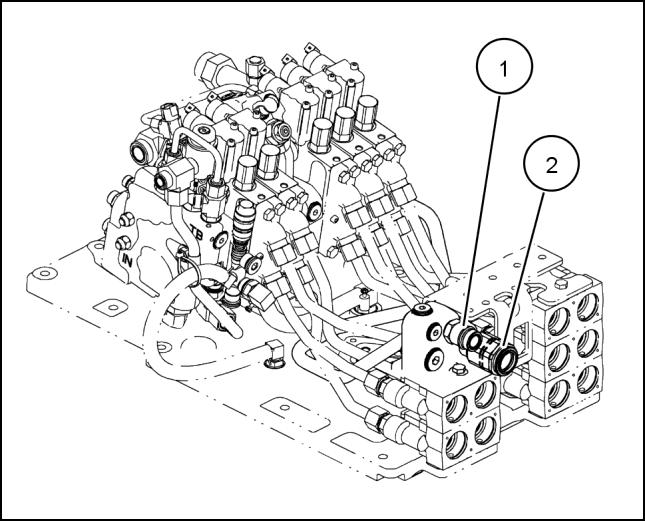
Priority regulator valve with pressure solenoid
NOTE: T8050 only.
The priority/regulator valve equipped with a pressure solenoid valve (1) which is not adjustable. The pressure solenoid uses feedback from the pressure transducer, through the transmission controller, to maintain a tighter tolerance on regulated system pressure. The solenoid maintains full regulated pressure to the transmission clutches regardless of temperature or other demands on the regulated pressure circuit.

RCPH07CCH020GAE 5
1. Pressure solenoid valve
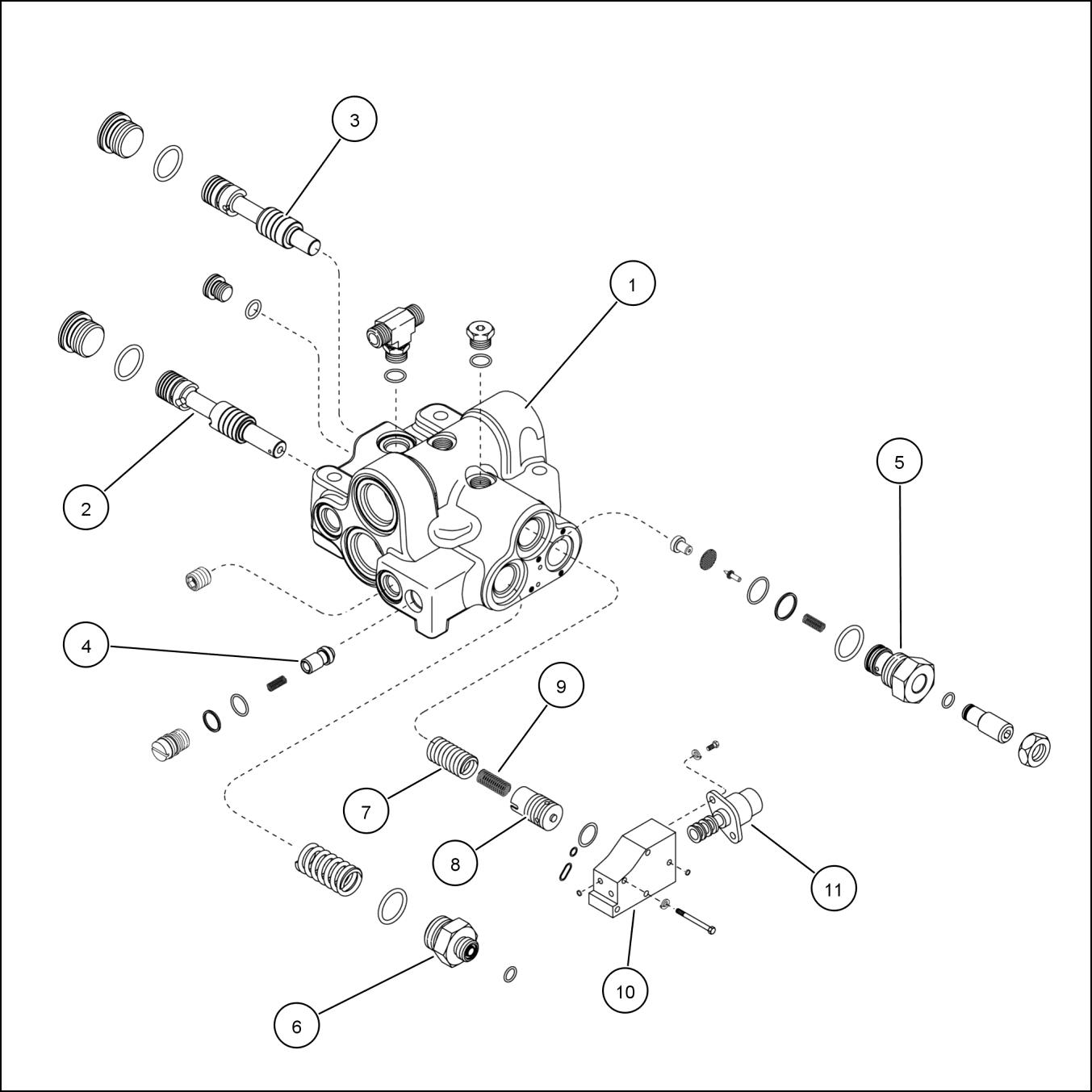
Control valve Priority/Regulator valve - Exploded view
T8010, T8020, T8030, T8040

1. Priority/regulator valve body
Priority valve spool
3. Regulator spool
4. Logic check valve assembly
RCPH07CCH028GAE 1
Regulated pressure adjustment assembly
Internal plug
5. Pilot relief assembly
2.
6. Orifice fitting
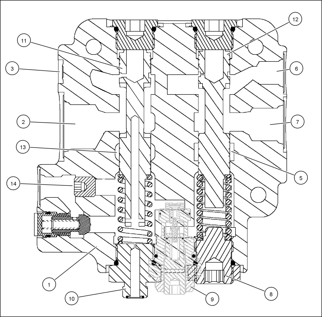
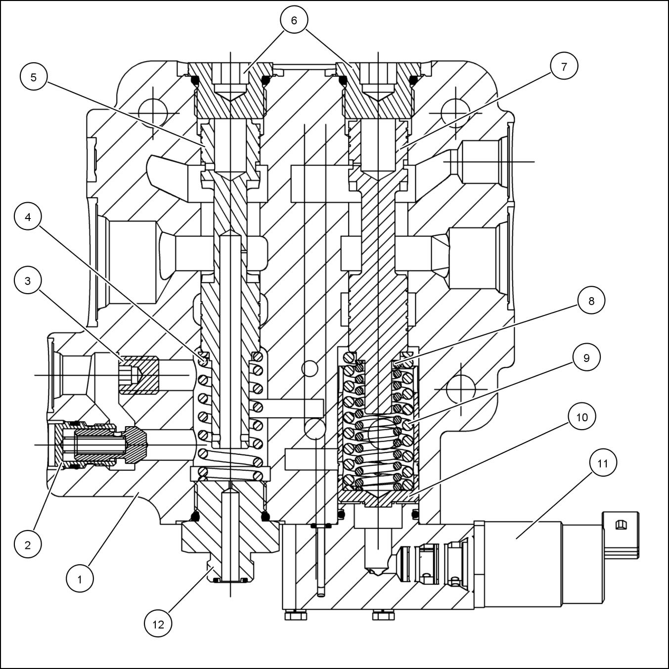
Control valve Priority/Regulator valve - Sectional view
T8010, T8020, T8030, T8040

1. Priority and regulator valve 7. Regulator spool
2. Logic check valve assembly
Regulator spring 3. Internal plug
Lock nut 4. Priority spring
Adjusting plug 5. Priority valve spool
Pilot relief valve assembly 6. Plug
Orifice fitting body assembly
Control valve Priority/Regulator valve - Exploded view
1. Priority/regulator valve body
7. Outer spring
2. Priority valve spool
8. Piston
3. Regulator spool
9. Inner spring
4. Logic check valve assembly
10. System pressure valve block
5. Pilot relief assembly
11. System pressure solenoid valve
6. Orifice fitting
Control valve Priority/Regulator valve - Sectional view
1. Priority and regulator valve
7. Regulator spool
2. Logic check valve assembly
8. Inner spring
3. Internal plug 9. Outer spring
4. Priority spring
Piston
5. Priority valve spool
System pressure solenoid assembly
6. Plug
Orifice fitting body assembly
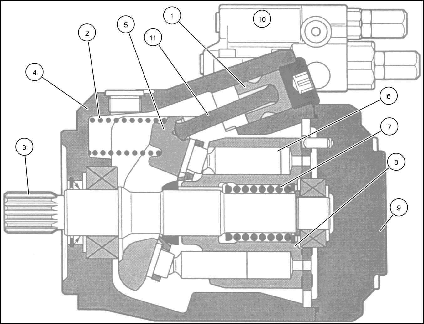
Pressure/flow compensating (PFC) pump - Dynamic description
T8010, T8020, T8030, T8040, T8050
NOTE: The principles of operation for the standard flow pump apply to both the optional high flow pump and Megaflow pump systems. The illustrations below depict the standard flow pump.
Principle of Control
All remote valves, the hitch control valve, the optional trailer brake and optional power beyond circuit contain a signal port. Each signal port directs a signal pressure, equal to the working pressure of that circuit, through signal lines and check valves to the pump compensator spool. The compensator angles the pump swash plate to meet system demands.
A check valve is located in each signal line between the control valves and the compensator spool. If several control valves are operated at the same time, the signal line at the highest pressure causes the other check valve(s) at the lower pressures to seat themselves. This prevents signal bleed off through other control valves and ensures that the highest signal pressure acts on the compensator spool.
The pump is designed to operate in two different modes according to the demand for flow and pressure. The modes ares:
• Low pressure standby: When there is no demand for flow or pressure, the pump provides just enough flow to make up for internal leakage in the hydraulic system at low pressure. In this mode the pump requires very little power to drive it.
• Pressure/flow delivery and compensation: When there is a demand for flow and pressure from the hydraulic system, the pump responds to provide only the flow required. This limits the power consumption of the system.
Thank you very much for your reading. Please Click
NOTE: If there is no response to click on the link above, please download the PDF document first and then clickonit.
1. Control piston
2. Control spring
7. Piston block loading spring
8. Piston block
3. Drive set 9. Back plate
4. Pump housing 10. Compensator assembly
5. Swash plate
6. Piston
11. Control piston rod

RCPH07CCH037FAE 2 Pressure compensator
1. Signal line pressure
2. Pump case drain
3. Control piston pressure
4. Piston pump outlet pressure
6. High pressure compensator spool
7. High pressure spring
8. Compensator assembly
9. Flow compensator springs
5. Flow compensator spool 10. Orifice plug
Low pressure stand by
When there is no demand for flow, there is no pressure signal feedback to the pump, and the pump enters low pressure standby mode. Since there is no place for pump oil to flow, pressure builds at the pump outlet passage. This pressure is directed, through internal passages in the pump back plate, to the end of the compensator spool opposite the spring.
The spring acting on the flow compensator spool allows the spool to move at a 23.5 - 27.0 bar (340 - 390 psi) differential pressure. At this pressure, the flow compensator spool moves down and allows oil to flow into the passage to the pump control piston.
Pressure on this control piston tilts the pump swash plate against the swash plate control spring to a near neutral position. In this condition, the pump provides just enough flow to make up for internal leakage, thus maintaining a minimum system pressure of 23.5 - 27.0 bar (340 - 390 psi).
The pump remains in the low pressure standby position as long as there is no pressure or flow demand from the hydraulic system. In this mode, the pump produces very little heat and absorbs very little horsepower from the engine.
Engine Start Up
Before the engine is started, the pump swash plate angle is at its maximum angle. As soon as the engine is cranked by the starter motor, the pressure and flow compensating (PFC) pump produces flow and pressure builds in the pump
delivery passage. When this pressure reaches 23.5 - 27.0 bar (340 - 390 psi) the pump enters its low pressure standby mode. This occurs almost instantly and makes engine starting easier.
Pressure/flow delivery and compensation
When oil is required in the system, flow is controlled by the difference in pressure at opposite ends of the compensator spool.
When a control valve is operated, pressure at the outlet of the piston pump drops slightly. Spring and signal line pressure shift the flow compensator spool away from the spring end, allowing oil from the control piston to drain past the spool and to tank.
As the oil drains out of the control piston, the swash plate angle increases and pump flow rises until the flow demand has been met. The flow from the pump is determined by the size of the orifice in the control valve which is being operated. This orifice is created by limiting the main valve spool travel within the control valve.
When a control valve is operated, oil pressure in the circuit being supplied increases to its operating pressure. This pressure is transmitted through the sensing line to the spring end of the compensator spool.
Increased flow demand
When an additional control valve is operated, pressure drops slightly at the pump pressure passage. The compensator spool moved up and allows the oil behind the control piston to drain to tank. The swash plate moves and pump flow increases until the extra demand for flow has been met.
Pressure at the pump outlet increases until it is 23.5 - 27.0 bar (340 - 390 psi) above the signal line pressure. This pressure increase moves the pump compensator spool against the spring, allowing sufficient flow past the spool to the control piston. This action on the piston moves the swash plate to a position where increased flow is maintained and the pressure stabilized.
Decreased flow demand
When flow demand is reduced, pump pressure increases until the pump outlet pressure exceeds the signal line pressure by more than 23.5 - 27.0 bar (340 - 390 psi). The flow compensator spool moves down to allow some oil to flow into the pump control piston. This action on the piston destrokes the pump against the spring and reduces pump flow.
When pump flow falls to match the reduced demand, the difference in pressure sensed on the opposite sides of the compensator spool returns to 23.5 - 27.0 bar (340 - 390 psi). The compensator spool moves and blocks off the passage to the control piston, which locks the swash plate at that pumping angle.
High pressure standby
The hydraulic system is protected by limiting its maximum pressure to 202 - 203 bar (2930 - 2950 psi) through a signal relief valve. This protection is required, for example, when a hydraulic cylinder reaches the end if its stroke or when an unconnected remote valve is operated.
NOTE: Hitch system pressure is not limited by a signal relief valve. Hitch system maximum pressure limit is 224 bar (3250 psi).
When system pressure reaches the setting of the high pressure compensator spool, the pump high pressure compensator spool shifts against its spring, allowing the full pump pressure to be applied to the pump control piston. This destrokes the pump very rapidly from full stroke to almost zero (within 8 to 10 milliseconds). The swash plate stabilizes to provide just sufficient flow to make up for internal leakage.
The pump remains in the high pressure standby mode until the valve in operation returns to neutral. When this occurs, signal line feed from the valve is cut off. Signal pressure drops because the drain orifice plug passage is open to the pump case drain. When there is no signal line pressure, the pump immediately returns to a low pressure standby condition.
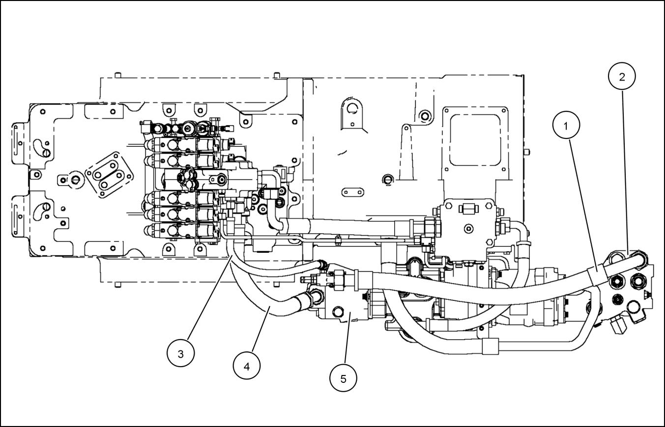
Pressure/flow compensating (PFC) pump Standard - Component identification
T8010, T8020, T8030, T8040, T8050

RCPH07CCH025FAE 1

RCPH07CCH017FAE 2
1. Remote manifold load sense tube
6. PFC piston pump
2. PFC pump to priority regulator valve
7. Remote manifold return (tube)
3. Remote manifold return (hose)
8. Remote manifold supply
4. Main filter assembly
9. Priority regulator valve
5. Pump load sense
Pressure/flow compensating (PFC) pump High flow - Component identification
T8010, T8020, T8030, T8040, T8050

1

2
RCPH07CCH018FAE
RCPH07CCH017FAE
1. Remote manifold load sense tube
6. High flow PFC piston pump
2. PFC pump to priority regulator valve
7. Remote manifold return (tube)
3. Remote manifold return (hose)
8. Remote manifold supply
4. Main filter assembly
9. Priority regulator valve
5. Pump load sense
Pressure/flow compensating (PFC) pump Dual flow - Component identification
T8010, T8020, T8030, T8040, T8050

RCPH07CCH027FAE 1
RCPH07CCH030FAE 2
84318454 14/03/2010 A.10.A / 116