Tractor


TK4020F /TK4020Y /TK4030 TK4030F /TK4030V /TK4040 TK4040PI /TK4050 /TK40S0PI /TK4060
SERVICE MANUAL
47830952 26/03/2015 EN
TK4020F , TK4020V , TK4030F , TK4030V , TK4030 , TK4040M , TK4040 , TK4050M , TK4050 , TK4060
Link Product / Engine
Product Market Product Engine
TK4020F Middle East Africa F5AE9484A
TK4020F Asia Pacific F5AE9484A
TK4020F Europe F5AE9484A
TK4020F Australia New Zealand F5AE9484A
TK4020V Asia Pacific F5AE9484A
TK4020V Australia New Zealand F5AE9484A
TK4020V Europe F5AE9484A
TK4020V Middle East Africa F5AE9484A
TK4030 Australia New Zealand F5AE9484B
TK4030 Middle East Africa F5AE9484B
TK4030 Asia Pacific F5AE9484B
TK4030 Europe F5AE9484B
TK4030F Middle East Africa F5AE9484B
IK4UJUI- Asia Pacific F5Ak9484B
TK4030F Europe F5AE9484B
TK4030F Australia New Zealand F5AE9484B
IK4UJ0V Asia Pacific F5Ak9484B
TK4030V Middle East Africa F5AE9484B
TK4030V Europe F5AE9484B
TK4030V Australia New Zealand F5AE9484B
TK4040 Middle East Africa F5AE9484G
TK4040 Australia New Zealand F5AE9484G
TK4040 Europe F5AE9484G
TK4040 Asia Pacific F5AE9484G
TK4040M Europe F5AE9484G
TK4040M
TK4040M
AsiaPacific F5AE9484G
Australia New Zealand F5AE9484G
TK4040M Middle East Africa F5AE9484G
TK4050 Europe F4CE9487N
TK4050
Australia New Zealand F4CE9487N
TK4050 Middle East Africa F4CE9487N
TK4050 Asia Pacific F4CE9487N
TK4050M Asia Pacific F4CE9487N
TK4050M Middle East Africa F4CE9487N
TK4050M Europe F4CE9487N
TK4050M
Australia New Zealand F4CE9487N
TK4060 Europe F4CE9487A
TK4060
Asia Pacific F4CE9487A
TK4060 Middle East Africa F4CE9487A
IK4UbU
Austraiia New Zealand F4CE9487A
47830952 26/03/2015
Contents INTRODUCTION Engi 10 [10.001) Engine and crankcase 10.1 [10.216] Fuel tanks................................................................................................................ 10.2 [10.400] Engine cooling system ............................................................................................ 10.3 Clutch 18 [18.104] Clutch hydraulic release control ..............................................................................18.1 [18.100] Clutch mechanical release control........................................................................... 18.2 [18.110] Clutch and components........................................................................................... 18.3 Transmission ................................................................................ 21 [21.114] Mechanical transmission ......................................................................................... 21.1 [21.118] Transmission/Rear drive .......................................................................................... 21.2 [21.140} Mechanical transmission internal components 21.3 [21.148] Transmission/Rear drive internal components 21.4 [21.160] Creeper 21.5 [21.162] Reverser 21.6 Rear axle 27 [27.100] Powered rear axle 27.1 [27.126] Spur gear and final drives 27.2 Power Take-Off (PTO)_____________________________________ 31 [31.114] Two speed rear Power Take Off (PTO) 31.1 Brakes and controls............................................................................33 [33.120] Mechanical service brakes..........................................................................33.1 [33.202] Hydraulic service brakes 33.2 Hydraulic systems ................................................................... 35 [35.114] Three point hitch control valve 35.1 47830952 26/03/2015
[35.322] Regulated/Low pressure system 35.2 [35.204] Remote control valves 35.3 Steering 46 [46.110] Steering clutch ......................................................................................................... 46.1 Tracks and track suspension ........................................................48 [48.130] Track frame and driving wheels 48.1 [48.100] Tracks...................................................................................................................... 48.2 |48.110] Front suspension...................................................................................................... 48.3 {48.114] Rear suspension 48.4 (48.134] Track tension units 48.5 |48.138] Track rollers 48.6 Electrical 55 (55.100] Harnesses and connectors......................................................................................55.1 OSS.201] Engine starting system 55.2 OSS.301] Alternator 55.3 [55.302] Battery 55.4 {55.640] Electronic modules 55.5 (55.404] External lighting 55.6 |55.408] Warning indicators, alarms, and instruments 55.7 t55.oTC FAULT CODES..........................................................................................................55.8 Platform, cab, bodywork, and decals...................................................90 |90.150] Cab.......................................................................................................................... 90.1 47830952 26/03/2015

INTRODUCTION 47830952 26/03/2015 1
Contents INTRODUCTION Safety rules 3 Basic instructions 7 Consumables 10 47830952 26/03/2015 2
Safety rules
Safety regulations
Warnlng and danger symbol
This warning symbol points out important messages con ceming your safety.

Carefully read the following safety regulations and observe advised precautions in order to avoid potential hazards and safeguard your health and safety.
In this manual the symbol is accompanied by the following key-words:
WARNING" \/\/bmings concerning unsuitable repair op eratJons that may jeopardise the safety of repair person nel.
•DANGER" - Specific warnings concerning potential haz "°‘”" ards for operator safety or for other persons directly or indirectly involved.
To prevent accidents
Most accidents or injuries that occur in workshops are the result of non-observance of simple and fundamental safety regulations. For this reason, in most cases these accidents can be avoided: by foreseeing possible causes and consequently acting with the necessary caution and care.
Accidents may occur with all types of vehicle, regardless of how well it was designed and built.
Acareful and judicious service technician isthebest guarantee against accidents.
Precise observance of the most basic safety rule is normally sufficient to avoid many sei1ous accidents.
•DANGER" Never carry out any leaning, lubrication or maintenance operations when the engine is running.
Safety regulations
General guldelines
• Carefully follow specified repair and maintenance procedures.
• Do not wear rings, wrisMatches, jewellery, unbuttoned or loose articles of clothing such as: ties, torn clothing, scarves, open jaclcets or shirts with open zips that may remain entangled in moving parts. It is advised to wear approved safety clothing, e.g: nomslip fooMear, gloves, safety goggles, helmets, etc.
• Do not carry out repair operations with someone sitting in the driver's seat, unless the person is a trained technician who is assisting with the operation in question.
• Do not operate the vehicle or use any of the implements from different positions, other than the driver's seat.
• Do not carry out operations onthe vehide with the engine running, unless specifically indicated.
• Stop the engine and ensure that all pressure is relieved from hydraulic circuits before removing caps, covers, valves, etc.
• All repair and maintenance operations must be carried out using extreme care and attention. 47830952
INTRODUCTION
28/O3f2015
• Service steps and platforms used in a workshop or in the field should be built in compliance with the safety rules in force.
• Disconnect the batteries and label all controls toindicate that the vehicle is being serviced. Biock the machine and all equipment which should be raised.
• Do not check or fill fuel tanks, accumulator battei1es, nor use starting liquid when smoking or near naked flames, as these fluids are inftammable.
• Brakes are inoperative when manually released for repair or maintenance purposes: use blocks or similar devices to control the machine in these conditions.
• The fuel nozzle should always be incontact withthe filling aperture: maintain this contact until the fuel stops flowing into the tank to avoid possible sparks due to static electricity build-up.
• Only use specified towing points for towing the vehicle. Connect parts carefully: make sure that all pins and/or locks are secured in position before applying traction. Never remain near the towing bars, cables or chains that are operating under load.
• Transport vehicles that cannot be driven using a trailer or a low-loading platform trolley, if available.
• When loading or unloading the vehicle from the trailer (or other means of transport), select a flat area capable of sustaining the trailer or truck wheels. Firmly secure the vehicle to the truck or trailer and lock the wheels in the position used by the carrier.
• Electric heaters, battery-chargers and similar equipment must only be powered by auxiliary power supplies with efficient ground insulation to avoid electrical shock hazards.
• Always use suitable hoisting or lifting devices when raising or moving heavy parts.
• Take extra care if bystanders are present.
• Never pour petrol or diesel oil into open, wide or low containers.
• Never use gasoline, diesel oil or other inflammable liquids as cleaning agents: use non inflammable, non toxic commercially available solvents.
• Wear safety goggles with side guards when leaning parts with compressed air.
• Limit the air pressure to a maximum of 2.1 bar, according to local regulations.
• Do not run the engine in confined 9paces without suitable ventilation.
• Do not smoke, usenaked ftames, or cause sparks inthe area whenfuel filling orhandling highly inflammabie liquids.
• Never use naked flames for lighting when working on the machine or checking for leaks.
• All movements must be carried out carefully when working under, on or near the vehicle. Wear protective equipment: helmets, goggles and special footwear.
• When carrying out checks with the engine running, request the assistance of an operator in the driver's seat. The operator must maintain visual contact with the servioe technician at all times.
• If operating outside the workshop, position the vehicle on a ftat surface and lock inposition. If working on a slope, lock the vehicle in position. Move to a ftat area as soon as is safely possible.
• Damaged or bent chains or cables are unreliable. do not use them for lifting or towing. Always use suitable protective gloves when handling chains or cables.
• Chains should always be safely secured: make sure that the hitch-up point is capable of sustaining the load in question. Keep the area near the hitch-up point, chains or cables free of all bystanders.
• Maintenance and repair operations must be cari1ed out in a clean and dry area. Eliminate any water or oil spillage immediately.
• Do not create piles of oil or grease-soaked rags: as they represent a serious fire hazard. Always store rags in a closed metal container.
Before stai1Jng the tractor or its attachments, checI‹, adjust and block the operator's seat. Also ched‹ that there are no persons within the vehicle or implement range of action.
• Empty pockets of all objects that may fall unobserved into the vehicle parts.
• In the presence of protruding metal parts, use protective goggies or goggles with side guards, helmets, special footwear and gloves.
INTRODUCTION
47830B52 20f03/201S 4
SERVICE MANUAL
Engine
47830952 26/03/2015 10
TK4020F , TK4020V , TK4030F , TK4030V , TK4030 , TK4040M , TK4040 , TK4050M , TK4050 , TK4060
Contents Engine 10 [10.001] Engine and crankcase 10.1 [10.216] Fuel tanks 10.2 [10.400} Engine cooling system 10.3 47830952 26/03/2015 10
Engine - 10 Engine and crankcase - 001
47830952 26/03/2015 10.1 [10.001] / 1
TK4020F , TK4020V , TK4030F , TK4030V , TK4030 , TK4040M , TK4040 , TK4050M , TK4050 , TK4060
Contents Engine 10 Engine and crankcase - 001 SERVICE Engine Remove .. ... . . . . . . . ... . . . . . . . ... .. 3 Install...............................................................................................................................................7 47830952 26f03f2015 10.1 {10.001ț / 2
Engine - Engine and crankcase


Engine - Remove
DANGER
Heavy obJectsI
Liftandhandle allheavy components usinglifting equipment withadequate capacity. Always support Make sure the work area is clear of all bystanders. Failure to comply will result In death or serious Injury.
NOTE: The pictures showing disassembly were made on a machine with a NEF engine. For the arrangement of the elements between the two engines, NSF and FSA, keep in mind that the gears of the timing system are respectively on the flywheel side for the former and on the fan sfde for the laner. The removal operations are similar for both engines. A note shows the differences between the two engines. Perform operations Clutch - Remove (18.110). prooeed as follows:
1. Remove the right-hand (1) and left-hand support of the safety roof.
2. Remove the left-hand (1) and right-hand shrouds ofthe radiator fans.
47830952 26/03/2015 10.1 |10.001] / 3
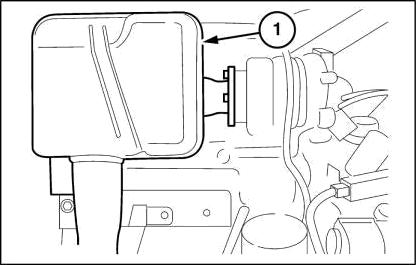
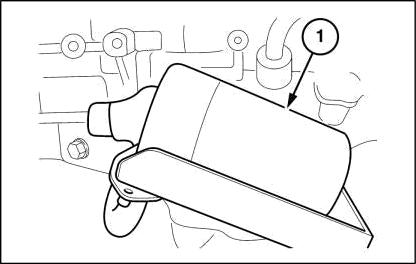
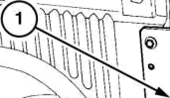
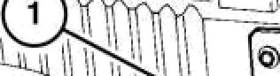
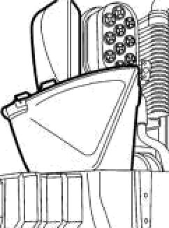
3. Take off the muffler (1) and related flame shield.
Then
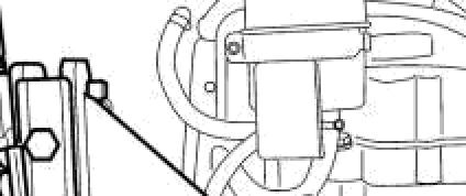
fiIOTE: On the FfiA engine, again on the right-hand side of the crankcase, on the cover of the engine oil coo/er there is a rigid sleeve where there is a plug, collect most of the coolant from the plug, then loosen the clamp on the flexible sleeve, exyacf /i and collect the rest of the coolant.
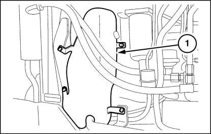
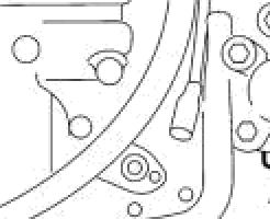
5. Detach the fuel pipe from the priming pump (1) and the return pipe (2) from the injection pump.
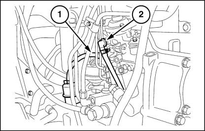


fiIOTE: On the FfiA engine, the injection pump, looking ai the machine from the same side, is on the ie/I and the priming pump is on the right.
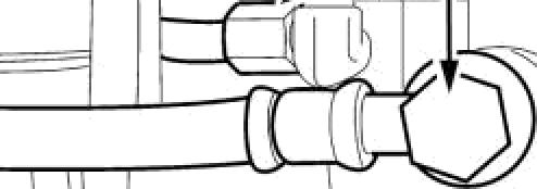
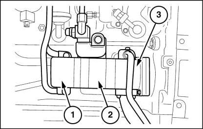
6. For models TK4050 and TK4060. Detach the flow and return pipes (1) from the heat exchanger.


NOTE: This applies only to NSF engines.


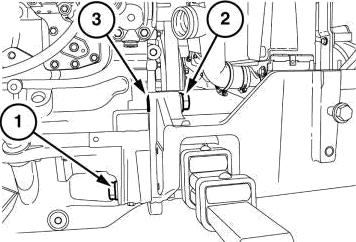
7. Detach the oil supply and intake tubes for the SteeringO-Matic on the unit pump (1). Also remove the tank with the support.

On the unit (2), only for models TK4050 and TK4060, remove the oil delivery pipe to the transmission and the bypass valve unit.
From the unit (3), remove the supply tube to the lift. Disconnect the intake tube. Remove the entire pump unit.
fiIOTE: On fhe FSA engine, looking at the machine from the same side, the pump unit, not w”ith three pumps but only two, in addition is mounted on the leR-hand side.
Engine - Engine and crankcase
4.
47830652 26/03/2015 10.1 |10.001] / 4
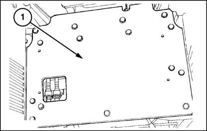
8. Remove the filter (1) with the supply tube to the pump.
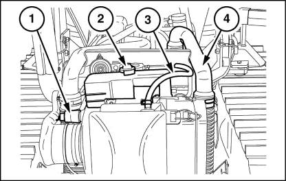
9. Detach from the engine side:
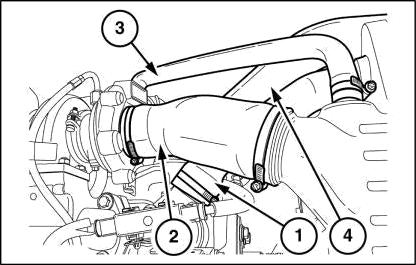
• Upper radiator sleeve (1)


• Air supply sleeve to the turbocharger (2)

• Oil vapor collection pipe from the engine breather (3)


• Air supply sleeve from the turbocharger to the intercooler (4)
On the left-hand side:
• Air supply sleeve from the intercooler to the intake manifold.
NDAP: On the F5 engine, the sleeves on tfie intercooler are reversed, that is, the pipe that is on tfie right-fiand side on tfie intercooler goes to the intake manifold. The pipe that is on the lelt-fiand side on the intercooler goes to the turbocharger outlet.
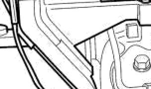
10. Disconnect the upper radiator support (1) from 1he damper support for the bonnet (2). Then remove it. Remove the relay of the grid heater (3), including the support and the supply cable, disconnecting it from the alternator, and of the supply to the grid heater, disconnecting itfromtheintake manifold. Also remove the battery charge cable from the alternator.
Engine - Engine and crankcase
47830B52 28/03/2015 10.1 [10.001] / 5 3 2
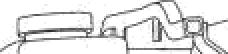
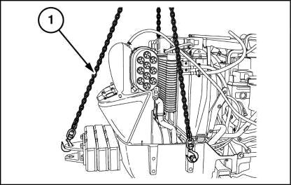
11. Sling the radiator support, tank, intercooler and air cleaner with a chain (1) and hook it onto the hoist.
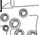
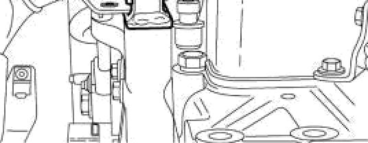
12. Disconnect the abovementioned support from the en gine by removing the screws (1) and (2) on the lefthand side. Do the same on the right-hand side. Remove the washers (3).
Engine Engine and crankcase
47830B52 2Bf03/2015 10.1 |10.001] / 6
Engine - Engine and crankcase
Engine - Install
WARNING
Avold in}uryI
Handle all parts carefully. Do not place your hands or fingers between parts. Use Personal Protectlve Equipment (PPE) as indicated In this manual, Including protective goggles, gloves, and safety footwear.
Failure to comply could result In death or serious injury.
To re-install the engine, proceed as follows:
• Mount the support for the radiator cores on the en gine with the four screws. Remember to insert the washers as a spacer on the I vo upper screws.
• Refit the hood damper support. Re-connect the upper radiator support. Refit the support with the grid heater relay and sum ply cable. Connect it to the alternator with the charge cable. Connect the supply cable to the relay at the grid heater element.
• Reinstall:
• Upper radiator sleeve
• Air cleanerAurbocharger sleeve
• Oil filter collection pipe/air cleaner
• Intercooler right-hand sleeve
On the left hand side:
• Intercooler IeftTand sleeve
• Refit the lift oil filter including the supply pipe to the pump.
• Refit the pump unit, including the oil supply pipe, to the lift. Reconnect the intake pipe to the pump. Connect the inlet pipe and the supply pipe to the Steering O-Matic pump. Also fit the tank and the related support.
For the TK4050 and TK4060 models, fit the bypass valve assembly and the oil supply pipe to the t am mission.
• Reconnect the supply to the heat exchanger pump on the bypass valve assembly. Reconnect the return to the intercooler assembly.
• Reconnect the fuel supply pipe to the priming pump. Reconnect the exhaust pipe to the injection pump.
• Reconnect the radiator lower sleeve and refit the plug.
• Refit the muffles and related flame shield.
• Refit the right- and left-hand fan guards.
• Refit the right- and left-hand support of the safety roof.
• Fill up the engine refrigerant with the product and quantity prescribed in Consumables ().
• Carry out the operations for the implement clutch Clutch - Remove (18.110).
47830B52 28/03/2015 10.1 [10.001] / 7
Index Engine 10 Engine and crankcase - 001 Engine - Install 7 Engine - Remove ........................................................................................................................................3 47830952 26f03f2015 10.1 {10.001ț / 8
- 10 Fuel tanks - 216
Engine
47830952 26/03/2015 10.2 [10.216] / 1
TK4020F , TK4020V , TK4030F , TK4030V , TK4030 , TK4040M , TK4040 , TK4050M , TK4050 , TK4060
Contents Engine 10 Fuel tanks - 216 SERVICE Fuel tank Remove Rear ..........................................................................................................................................3 Install Rear 6 Remove Front 7 Install Front 9 47830952 26f03f2015 10.2 {10.216} / 2
Fuel tank - Remove - Rear
DANGER
Heavy obJectsI

Lift and handle all heavy components using lifting equipment with adequate capacity. Always support unlts or parts with sultable slings or hooks. Make sure the work area Is clear of all bystanders. Failure to comply will result In death or serlous Injury.

Proceed as follows.
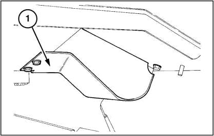
1. After disconnecting the operator present switch, loosen the retaining bolts and remove the seat(1).
2. Loosen the retaining bolts and detach the seat mounting (1).
NOTE: The rear tank varies from models TK4020, TK4030 (special) to models TK4040, TK40fi0, TK4060 (open Tield). There are sI”ighi differences in capacity and in shape.

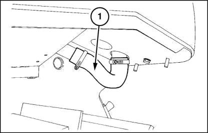
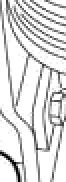
3. Whilst detaching the support (1) (Fig. 2), disconnect the P.T.O. switch connection (1).
Engine - Fuel tanks
47830952 26/03/2015 10.2 |10.216] / 3


Engine - Fuel tanks
4. Drain the fuel from the front tank.
s. retaining bolts and remove the rear tank
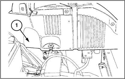
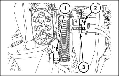
6. Disconnect electrical connections (1) and (2) - rear lights and fuel level gauge.
7. Remove the clamp. Detach the tank breather pipe (3).
47830B52 20/03/2015 10.2 (10.216] / 4 1
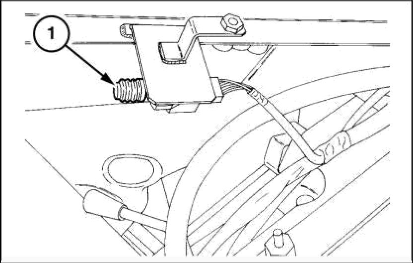
8. Remove the retaining bolts. Detach the electilc cable clamp (1) and breather pipe.
Engine - Fuel tanks
 9. Working from under the left-hand fender, remove the retaining bolts. Remove the fuel pipe guard (1).
10. Remove the rear tank clamps and sleeve (1). If necessary, remove the connection pipe of the front tank.
9. Working from under the left-hand fender, remove the retaining bolts. Remove the fuel pipe guard (1).
10. Remove the rear tank clamps and sleeve (1). If necessary, remove the connection pipe of the front tank.
47830952 26/03/2015 10.2 |10.216] / 5
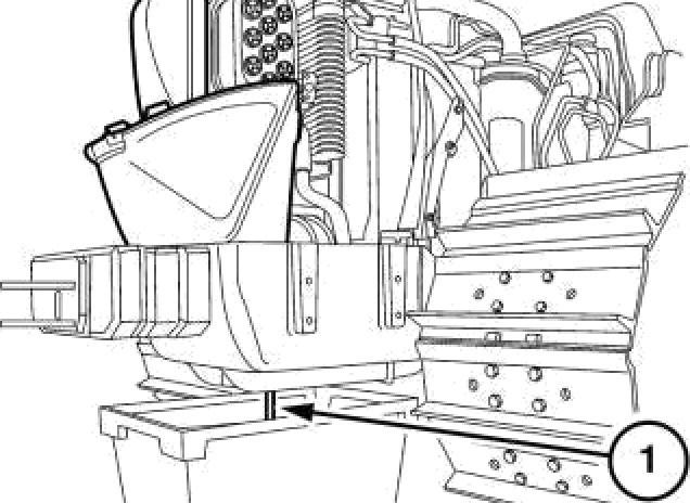
11. Remove theretaining bolts. Remove the rear tank (1).
Fuel tank - Install - Rear
@ WARNING
Avoid inJuryI
Handle all parts carefully. Do not place your hands or fingers between parts. Use Personal Protectlve Equlpment (PPE) as Indicated in this manual, including protective goggles, gloves, and safety footwear. Failure to comply could result in death or serious injury.
To refit, proceed as follows.
• Fit the rear tank with the relative retaining bolts.
• Refit the sleeve and clamps to the rear tank and, if removed previously, the connection pipe of the front tank.
• Working from under the left-hand fender, fit the fuel pipe guard with the relative retaining bolts.
• Refit the electric cable damp and the breather pipe with the relative retaining bolts.
• Refit the tank breather pipe and clamp.
• Reconnect the electrical connections for the rear lights and the fuel level gauge.
• Fit the rear tank cover and therelative retaining bolts.
• Connect the connection for the power take-off switch.
• Refit the seat mounting and the relative retaining bolts.
• Fit the seat and the related retaining bolts. Reconnect the operator present switch.
• Fill up the fuel with the product and quantity pre scribed in Consumables (). Bleed the air from the fuel circuit.
Engine - Fuel tanks
47830B52 20f03/2015 10.2 |10.216] / 6
Engine - Fuel tanks
Fuel tank - Remove - Front
DANGER
Heavy obJectsI
Lift and handle all heavy components using lifting equipment with adequate capacity. Always support unlts or parts with sultable slings or hooks. Make sure the work area Is clear of all bystanders. Failure to comply will result In death or serlous Injury.
NOTE: The front tank varies from models TK4020, TK4030 (special) to models TK4040, TK4050, TK4060 (open field). There are differences in capac'ity and shape. Proceed as follows.
1. Fully raise the engine hood (1). Disconnect the supporting damper and secure the damper to the restraint bar.
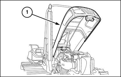
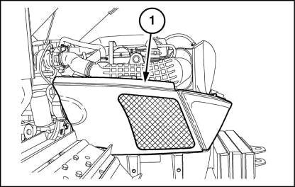
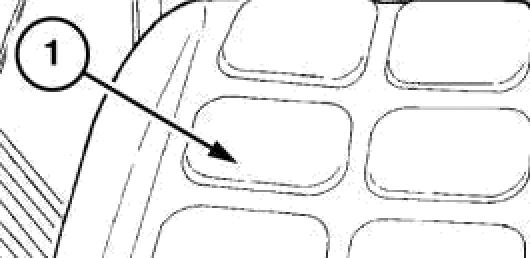
2. Detach the plastic side panels (1) on both sides.
3. Drain the fuel from the front tank (1).
47830952 26/03/2015 10.2 |10.216] / 7
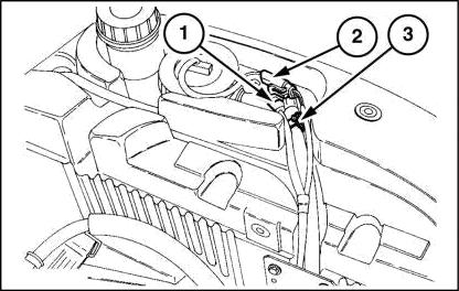
4. Disconnect the electrical connections from the clogged filter detector (1), the horn and the Nel level sensor for the front tank.


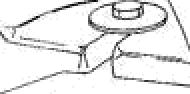
Extract the expansion tank (2). Stand the tank on the radiator.
Loosen the metal clamps and remove from the tank: the breather pipe (3), on the right-hand side, the supply pipe for the priming pump and the return pipe from the injection pump. On the left-hand side at the bottom disconnect the pipe connecting the two tanks. Disconnect the right- and left-hand pipe (4) from the intercooler.
5. Loosen the metal clamps and remove the screw from the sleeve (1) joining the air cleaner and turbocharger 1 inlet hose. Then remove the sleeve. Remove the right- (1) and left-hand panel fastener, hood locking catch and the two spacers alongside the catch from the tank.
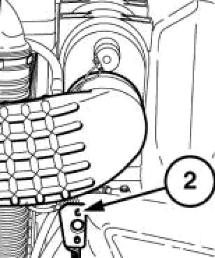
6. Loosen the clamps on the air cleaner and on the fan manifold retaining the dust ejector pipe (1). Then re move the pipe (where applicable).


On models TK40S0 and TK4060, turn the screw (2) by half a turn and extract the heat exchanger (3). Then place the heat exchanger so it does not hinder the up ward movement of its support.


7. On the right-hand side, take out the screw (1) fasten ing the intercooler support, together with the heat exchanger support, expansion tank support andhorn. On the other side, take out the corresponding screw and, on the top left- and right-hand side, remove the retaining bolts on the radiator and raise everything. Free thetankby taking out the twoscrews onthe clamp (2). Then under the front suspension support remove the related fasteners. Raise the tank.
Engine - Fuel tanks
MOLJ¥1 4
47830B52 20f03/2015 10.2 |10.216] / 8
1 ”