

DOWNLOAD MANUAL
Contents
INTRODUCTION
Engine
[10.501] Exhaust Gas Recirculation (EGR) exhaust treatment
[18.1 10] Clutch and components
ransmission
14] Mechanical transmission
[21.140] Mechanical transmission internal components
[21.1 12] Power shuttle transmission
[21.154] Power shuttle transmission internal components
[21.120] Gearbox
[21.160] Creeper
[21.162] Reverser
Four-Wheel Drive (4WD) system
[23.202] Electro-hydraulic control
Front axle system
DOWNLOAD MANUAL
Brakes and controls
[33.202] Hydraulic service brakes
[33.220] T railer brake hydraulic control
[33.224] T railer brake pneumatic control
Hydraulic systems
Hydraulic systems
Fixed displacement pump
Auxiliary hydraulic valves and lines
Main lift system
Steering
[41.200] Hydraulic control components
[41.206] Pump
[41.216] Cylinders
Wheels
Front wheels
Cab climate control
[50.200] Air conditioning
Electrical systems
Electrical system
Harnesses and connectors
Cab engine controls
Engine control system
Engine starting system
Alternator
Battery
Cold start aid
Fuel tank system
Fuel injection system
Engine oil system
Electronic modules
T ransmission control system
Rear Power T f (PT control system
Front Power T f (PT control system
[55.512] Cab controls . . . . .
[55.130] Rear hitch electronic control system
[55.408] W arning indicators, alarms, and instruments . . . .
DOWNLOAD MANUAL
Note the Owner
Note the Owner
General instructions
Important notice
All maintenance and repair operations described this manual should carried out exclusively the NEW LAND authorised All instructions detailed should carefully observed and special equipment indicated should used necessary
Everyone who carries out service operations described without carefully observing these prescriptions will directly responsible deriving
Shimming
each select adjusting measure them individually using a micrometer and then sum recorded values. not rely measuring the whole shimming set, which may incorrect, rated value indicated for each
Rotating shaft seals
T o correctly install rotating shaft observe the following instructions:
• Let the seal soak into the same oil will seal for least half hour before mounting.
• Thoroughly clean the shaft and ensure that the shaft working surface not
• Place the sealing lip towards the case a hydrodynamic consider the shaft rotation direction and orient grooves order that they deviate the fluid towards the inner side the
• Coat the sealing lip with a thin layer lubricant (oil rather than grease) and fill with grease the gap between the sealing lip and the dust lip double lip
• Insert the seal into its seat and press down using a flat tap the seal with a hammer a
• T ake care insert the seal perpendicularly its seat while you are pressing it. Once the seal settled, ensure that contacts the thrust element
• T o prevent damaging the sealing lip against the shaft, place a suitable protection during installation.
O - rings
Lubricate the O - rings before inserting them into their seats. This will prevent the O - rings from rolling over and twine during mounting which will jeopardise
Sealers
Apply one the following sealers: R SILMA RHODORSIL CAF 1 , L OCTITE ® P IASTIC G ASKET over the mating surfaces marked with
Before applying the sealer , prepare the surface follows:
• Remove possible scales using a metal
• Thoroughly degrease the surfaces using one the following cleaning agent: petrol a water and soda
Bearings
advisable heat the bearings - ( 176 - 194 ) before mounting them their shafts and cool them down before inserting them into their seats with external tapping.
Roll pins
When fitting straight roll pins, ensure that the pin notch oriented the direction the fort stress the pin. Coil roll pins can installed any
• T o transfer a failed tractor , use a trailer a low loading platform trolley
• T o load and unload the machine from the transportation select a flat area providing a firm support the trailer truck Firmly tie the machine the truck trailer platform and block wheels required the forwarder
• For electrical battery - chargers and similar equipment use exclusive auxiliary power supplies with a ficient ground avoid electrical shock
• Always use lifting equipment and similar appropriate capacity lift move heavy components.
• Pay special attention
• Never pour gasoline diesel oil into open, wide and low containers.
• Never use diesel oil other flammable liquids cleaning Use nonflammable nontoxic etary
• W ear protection goggles with side guards when cleaning parts using compressed air
• not exceed a pressure 2.1 bar ( 30.45 psi ) , accordance with local
• not run the engine a closed building without proper
• not use open cause sparks the nearby area when filling fuel handling highly flammable liquids.
• not use flames light sources when working a machine checking for
• Move with caution when working under a tractor , and also near a tractor . W ear proper safety accessories: goggles and special footwear
• During checks which should carried out with the engine ask assistant seat the operator ’ s seat and keep the service technician under visual control any
• case operations outside the drive the tractor a flat area and block working incline cannot first block the tractor carefully Move a flat area soon possible with a certain extent safety
• Ruined plied cables and chains are unreliable. not use them for lifting trailing. Always handle them wearing gloves proper
• Chains should always safely Ensure that fastening device strong enough hold the load persons should stop near the fastening trailing chains
• The working area should always kept CLEAN and Y Immediately clean any spillage water
• not pile grease oil soaked they constitute a great fire Always place them into a metal container Before starting the tractor its adjust and block the operator ’ s Also ensure that there are persons within the tractor attachment operating range.
• not keep into your pockets any object which might fall unobserved into the tractor ’ s inner
• Whenever there the possibility being reached ejected metal parts similar , use protection eye mask goggles with side special footwear and heavy
• W ear suitable protection such tinted eye special gloves and footwear whenever necessary carry out welding All persons standing the vicinity the welding process should wear tinted eye NEVER LOOK A T THE WELDING ARC YOUR EYES ARE NOT SUIT ABL Y
• Metal cables with the use get frayed. Always wear adequate protections (heavy gloves, eye protection, etc.)
• Handle all parts with the greatest Keep your hands and fingers far from moving gears and similar Always use approved protective such eye heavy gloves and protective footwear
Start
• Never run the engine confined spaces which are not equipped with adequate ventilation for exhaust gas
• Never bring your body , fingers near fans rotating
Contents
DIAGNOSTIC
3710 - Lambda sensor - signal not plausible [ECU]
3766 - Diesel particulate filter pressure sensor: Fault check for the pressure sensor plausibility
3796 - Diesel particulate filter pressure sensor hose line error
3825 - Short circuit over load error for H - bridge [ECU]
Diesel Particulate Filters (DPF) - T orque

Diesel
Particulate Filters (DPF) - General specification

Measurements respect for installing the filter - Legend components - Legend sensor fixing holes:
1
- ( - )
Distance between the two bands the the one with the set fixing holes (10) and the one with the adjustable fixing holes
- ( - )
Distance between the centre the turbine the centre the union the decoupler / turbine and the adjustable filter fixing bushings (12)
134 - ( 5 - )
Distance between the centre the turbine the centre the union / turbine and the band supporting surface (4) with set fixing holes the filter
Band supporting surface with set fixing holes.
Initial part the DPF filter , connected with the sleeve (15) the Middle part the DPF filter , inside which there the ceramic part clean.
End part the DPF filter , connected with the sleeve (14) the exhaust
Clamp retaining the middle part (6) \ end part (7)
Clamp retaining the middle part (6) \ initial part (5)
Band with the set fixing
Band with the adjustable fixing
Threaded screwing them out enables changing the adjustment distance (3)
Grub screw fixing the bushing (12)
Filter outlet inserted the exhaust
Union joining the filter the
Clamp fixing the union (15) the filter
T utor , protects the decoupler during the handling from the supplier , dismantled after assembly (it advised keep one hand and reassemble before starting disassemble the filter that the decoupler undergoes deformation).
Gas pressure detection after the middle part the filter , the pipe that goes the dif ferential pressure sensor connected
Gas pressure detection before the middle part the filter , the pipe that goes the dif ferential pressure sensor connected
Exhaust gas temperature sensor from the
Exhaust gas temperature sensor the intake the middle part the filter 22. Lambda sensor .
Diesel Particulate Filters (DPF) - Dynamic description
A diesel particulate filter (DPF) a device designed remove polluting diesel engine particulate from exhaust gas when needs
The diesel particulate filter can regenerated automatically forcing.
The regeneration process signaled the operator the central monitor the dashboard and with acoustic The indication necessary for the purposes safety warn the operator about the high exhaust temperature reached during the
The automatic regeneration shall not fect engine
During the the operator can continue working normally
Under certain operating conditions automatic regeneration might not completed (engine continuously stopping and lengthy periods idle speed) and must then

The start automatic highlighted with the following warning light blinking the dashboard and the same symbol appears every 5 minutes the central monitor with the word “ON” combined with a single concluding the operation the symbol appears with the word “OFF“.
When the level soot exceeds a certain the electronic control unit asks you proceed with manual filter regeneration.
NOTICE: the filter not regenerated when whether manually the functionality the filter Continuing ignore this besides greatly reducing engine horsepower , damages the filter such extent that necessary for the dealer replace the filter with a new one.
When the following warnings appear the dashboard necessary proceed follows:
DPF regenerated
Start automatic regeneration with the control, start forced regeneration
Image legend:
W arning light the dashboard Flasher f Central display

ANIL15TRO1986AA 1
DPF regenerated Low severity
Automatic regeneration only start forced generation with control

ANIL15TRO1987AA 2
DPF regenerated High severity
Automatic regeneration only start forced generation with control

DPF damaged technical support required
Automatic and forced regeneration inhibited
ANIL15TRO1988AA 3

ANIL15TRO1989AA 4
Diesel Particulate Filters (DPF) - Remove
Raise the disconnect the headlights connector from the engine Remove the See T railer brake pneumatic control - Remove
NOTE: Remove the hinge from the support leaving this under the
Remove the side panels both

Loosen the clamp the connection pipe (1) between the air cleaner (3) and unscrew the retaining screws the air intake pipe (2) then slide towards the front that comes out the filter ter disconnecting the clogged filter sensor remove the filter from the bonnet

Disconnect the connectors the pressure dif ferential sensor (1) , the two temperature and the lambda sensor Loosen the system heat shield (2) Position everything the left - hand side the

Remove the bonnet support (1)

Unscrew the pressure dif ferential unit (1) with its pipes, clamps and sensor
Unscrew the temperature sensor (2)

Unscrew the filter ’ s upper heat shield (1) , the lower one stays

Mark the filter shown the
NOTE: The right - hand marking must include the first part the filter , the central part the filter (1) , and the clamp that joins them (2) The left - hand marking will include the central the left - hand and the clamp (3)

ANIL15TRO1998AB
Loosen the clamp (1) joining the muf fler the DPF outlet The clamp (2) that keeps the outlet tube the filter parallel the first section the filter

1 Remove the left - hand clamp (1) fastening the filter the

12. Loosen the left - hand clamp (1) fastening the middle and left parts the filter
ANIL15TRO2001AB
Remove the left - hand part the filter (1) , with the clamp (2) , retrieving the copper

after you have loosened the right - hand clamp (1) , remove the central part the filter (2)

Diesel Particulate Filters (DPF) - Install
NOTE: For the torque settings please refer Diesel Particulate Filters (DPF) - T orque (10.501)
- assemble the central part the DPF filter (2) with the relevant T ighten the clamp (1) , paying tention the orientation the
- assemble the left - hand part the DPF filter (1) with the relevant clamp (2) T ighten the paying tion the orientation the parts.
NOTE: the clamp and the seal are rusty a poor change the clamp and the
Reassemble the left - hand clamp (1) fastening the filter the
Position the collar (1) fastening the filter pipe the muf fler T ighten Also tighten the top the collar (2) that fixes the pipe the
- fit the filter upper heat shield (1) .
- fit the temperature sensor (2) and the pressure ferential assembly (1) , complete with and sensor ANIL15TRO2009AB
Refit the hood support (1) ANIL15TRO2010AB
Refit the system heat shield (2) Reconnect the sure sensor , lambda sensor , and pressure dif ferential sensor (1) Position the wire necessary , secure the wire harness with straps.
Fit the air cleaner (3) onto the hose (1) that connects the air cleaner the Then secure the hose the hood support with the relevant
10. T ighten the clamp the hose. Run the intake duct (2) toward the filter Then tighten with the relevant Reconnect the connector the clogged filter sensor
1 - assemble the side panels (2) and the bonnet (1) , T railer brake pneumatic control - Install
Diesel Particulate Filters (DPF) - Remove
Raise the Disconnect the headlight connector from the engine after you have secured the hood the hoist with a remove the See T railer brake pneumatic control - Remove (33.224)
Remove the side panels both
- with support
With the controller for recovering the gas from the airconditioning recover the gas (1)
Disconnect the air conditioning pipes (1) , the control panel side.

Loosen the clamp (1) retaining the air cleaner / turbine connection Loosen the bolts the air intake pipe (2) Then slide the pipe toward the front make the pipe come out the air cleaner
Disconnect the connector the clogged filter sensor , unscrew the filter (3) from the hood support and extract

Disconnect the connectors the pressure dif ferential sensor (1) , the two temperature and the lambda sensor Loosen the system heat shield (2) Position everything the left - hand side the engine.

Remove the complete hood support (1) . ANIL15TRO2017AB
the gap the left - hand side the reservoir for the behind the filter , remove the bolts (1) that join the cross support (2) the filter and the rear support (3)


Remove the brakes reservoir heat shield (1) ANIL15TRO2019AB
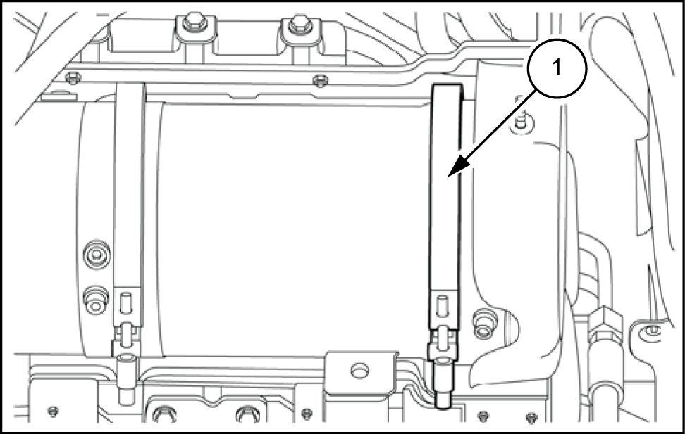
1 Loosen the clamp (1) fastening the exhaust pipe the DPF filter
12. Using a belt, sling the muf fler , two points least, take the slack with a Remove the bolts (2) that secure the exhaust pipe (1) the support (3) Then extract all the pipe from the right - hand side the tractor and put down a pallet the

13. Put two eyebolts (1) the screws retaining the upper heat shield the filter Using a hook the filter (2) and tension the

the left - hand under the filter remove the two screws (1) the adjustment bushings (3) the filter left support (2)
NOTE: After taking out the unscrew the bushings create a gap between the filter assembly and the left

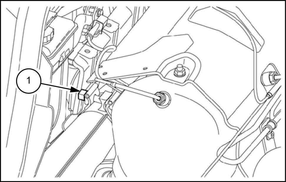
the right - hand loosen the clamp (1) that secures the filter decoupler the Move the clamp toward the T ake out the three hex socket screws (2) fastening the right support (3) the transversal
NOTE: These screws have been fitted the supplier and a few drops Loctite have been used prevent over from coming

16. Using the hoist, raise the filter , taking great care that there are wiring harnesses and tie - - rods connected obstructing the then rest the filter with the cross support a
NOTE: W ith the machine these conditions ble work the for example the valve cover , the right - hand support not possible reassemble the filter without making any special adjust-