[25.108] Final drive hub, steering knuckles, and shafts .
[25.122] Axle suspension control
Rear axle system
Powered rear axle
Rear bevel gear set and dif ferential
Planetary and final drives
Rear axle track yoke assembly
[31.104] Rear electro-hydraulic control
[31.1 10] One-speed rear Power T ake-Of f (PT
Remote control valves
Reservoir , cooler , and filters
Combination pump units
Hitches, drawbars, and implement couplings .
[37.1 10] Rear three-point hitch
Front hitch
Frames and ballasting
[39.100] Frame
Steering
Steering control
Hydraulic control components
Pump
Autoguidance steering
Auxiliary steering
Wheels
[44.520] Rear wheels
racks and track suspension
[48.100] T racks
[48.130] T rack frame and driving wheels
[48.134]
[48.138] T rack rollers
[55.000] Electrical system
Fuel injection system
Engine cooling system
Engine oil system
Engine intake and exhaust system
Engine control system
T ransmission control system
Front axle control system
Steering control system
V and (HV AC) control system
Harnesses and connectors
Rear hitch electronic control system
Battery
W arning and instruments
[55.512] Cab controls .
Electronic modules
Selective Catalytic Reduction (SCR) electrical system
[55.DTC] F AUL T CODES
General specification - Engine
General specification - Power train
Capacities
Product identification
Product identification - Machine orientation
Foreword - Important notice regarding equipment servicing
All repair and maintenance work listed this manual must carried out only qualified dealership strictly complying with the instructions and whenever the special
Anyone who performs repair and maintenance operations without complying with the procedures provided herein shall responsible for any subsequent
The manufacturer and all the organizations its distribution chain, including - without limitationnational, regional, local reject any responsibility for damages caused parts and / components not approved the facturer , including those used for the servicing repair the product manufactured marketed the manufacturer any case, warranty given attributed the product manufactured marketed the manufacturer case damages caused parts and / components not approved the manufacturer
The manufacturer reserves the right make improvements design and changes specifications any time without notice and without incurring any obligation install them units previously and illustrative material herein are accurate known time publication but are subject change without notice. case refer your NEW HOLLAND Sales and Service
Safety rules
Personal safety
This the safety alert used alert you potential personal injury Obey all safety messages that follow this symbol avoid possible death injury
Throughout this manual you will find the signal words W and CAUTION followed special These precautions are intended for the personal safety you and those working with
Read and understand all the safety messages this manual before you operate service the
DANGER indicates a hazardous situation not will result death serious injury
W ARNING indicates a hazardous situation not could result death serious injury
CAUTION indicates a hazardous situation not could result minor moderate injury
F AILURE T O FOLLOW
Machine safety
NOTICE: Notice indicates a situation that, not avoided, could result machine property damage.
Throughout this manual you will find the signal word Notice followed special instructions prevent machine property damage. The word Notice used address practices not related personal safety .
Information
NOTE: Note indicates additional information that clarifies other information this
Throughout this manual you will find the word Note followed additional information about a step, other information the The word Note not intended address personal safety property
Safety rules - General maintenance safety
General maintenance safety
Keep the area used for servicing the machine clean and dry Clean spilled
Service the machine a level
Install guards and shields after you service the machine.
Close all access doors and install all panels after servicing the
not attempt clean, lubricate, clear obstructions, make adjustments the machine while motion while the engine
Always make sure that working area clear tools, parts, other persons and pets before you start operating the
Unsupported hydraulic cylinders can lose pressure and drop the equipment, causing a crushing hazard. not leave equipment a raised position while parked during unless the equipment securely
Jack lift the machine only jack lift points indicated this manual.
Incorrect towing procedures can cause When you tow a disabled machine follow the procedure this Use only rigid tow
Stop the remove the key , and relieve pressure before you connect disconnect fluid
Stop the engine and remove the key before you connect disconnect electrical connections.
Scalding can result from incorrect removal coolant
Cooling systems operate under Hot coolant can spray out you remove a cap while the system hot. Allow the system cool before you remove the cap. When you remove the turn slowly allow pressure escape before you completely remove the
Replace damaged worn electrical
The exhaust and hydraulic lines may become hot during T ake care when you service such Allow surfaces cool before you handle disconnect hot W ear protective equipment when
When follow the instructions the Always disconnect the battery before you weld the Always wash your hands after you handle battery
SER VICE MANUAL
Engine - Overview
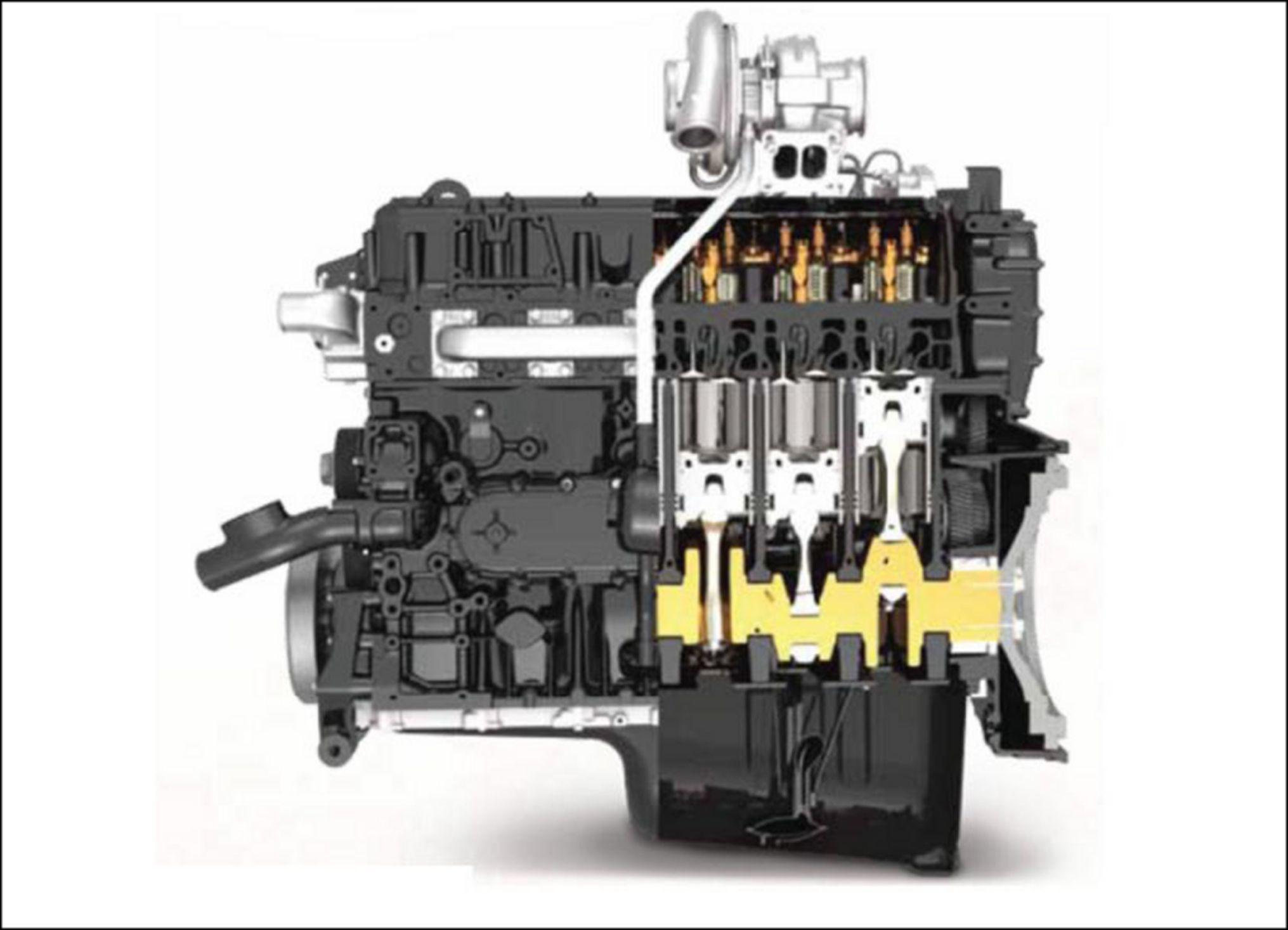
The Cursor® 9
The Cursor® 9 a state the art engine developed Fiat Powertrain T echnologies (FPT) The Cursor® 9 used the tractors has some significant internal and external dif ferences from Cursor® 9 engines used other CNH There are procedures specific the engines that are dif ferent from the Cursor® 9 used other CNH These changes were made fit the engine into the series frames without losing our featured visibility around the hood and
The Cursor® 9 engine was introduced the CNH combines 2006 and migrated into the series has proven itself a consistent reliable performer The introduction the series brings new heights with 275 ( 374 ) (rated) and 316 ( 429 ) power boost
• 6 cylinder , turbocharged and aftercooled
• Single overhead cam with roller rocker arms
• W astegate turbo / Electronic V ariable Geometry T urbocharger (EVGT)
• High pressure common rail fuel system
• Selective Catalytic Reduction (SCR) emissions control
• TIER compliant without internal external Exhaust Gas Recirculation (EGR)
RAIL15TR00417GA 1
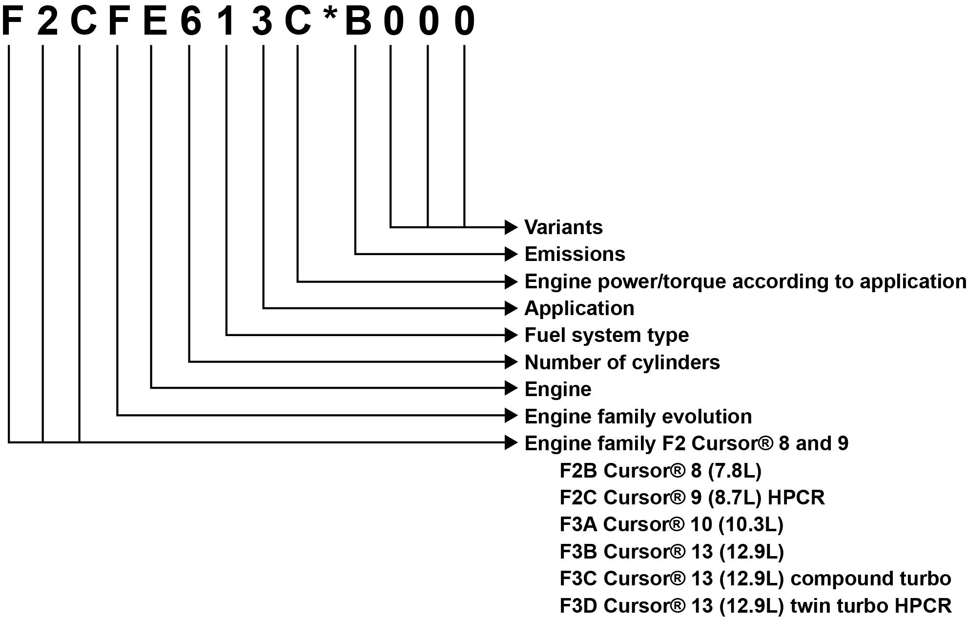
FPT model number designation
NOTE: The FPT engine designation code has evolved over the This the best current information and may not applicable previous FPT
RAIL15TR01380GA
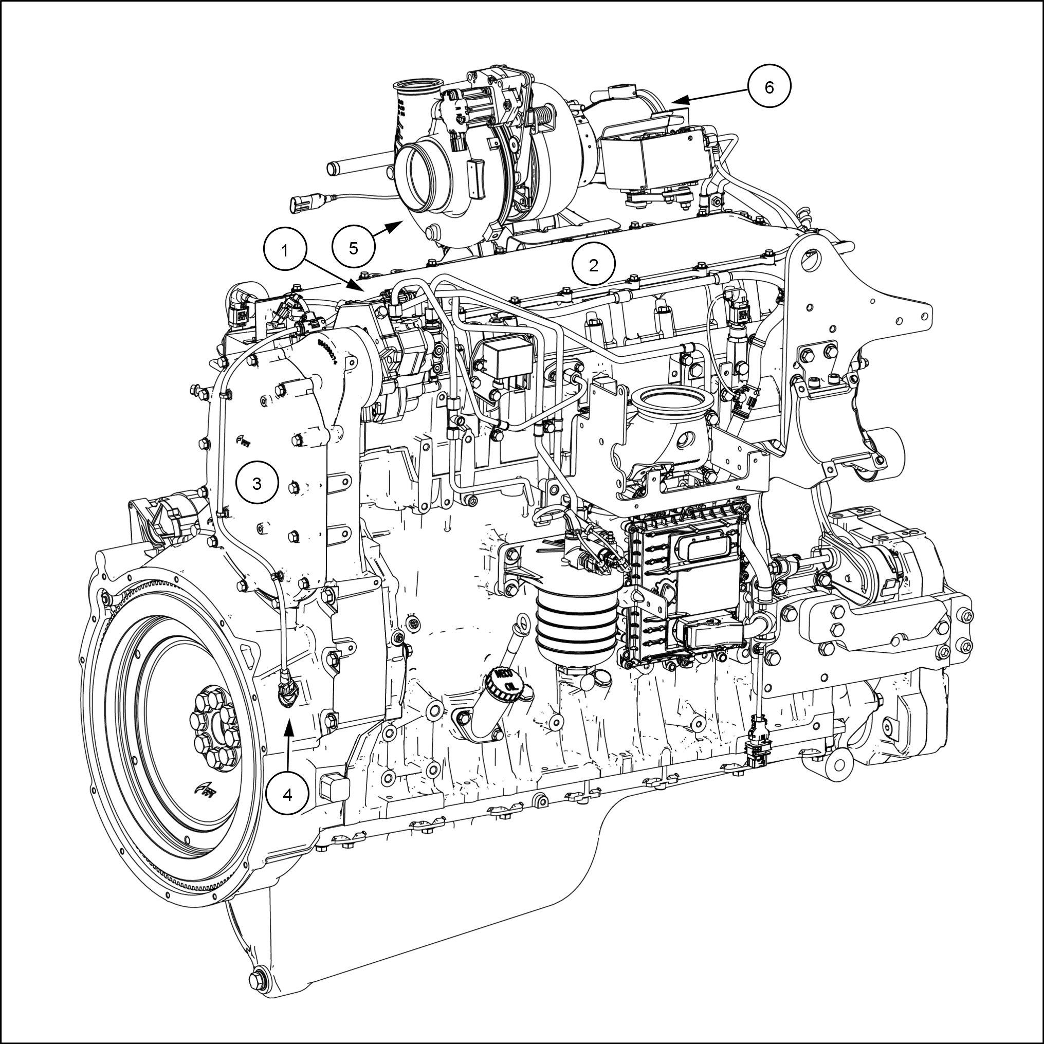
V isual external differences for T8. tractor engines
There are a few things that make the FPT Cursor® 9 engine used the T8. tractors visually and mechanically dif ferent from other Cursor® 9
3
The fuel pump sits higher and closet the center line the A two piece valve cover assembly that allows for valve adjustment without removing the entire cover
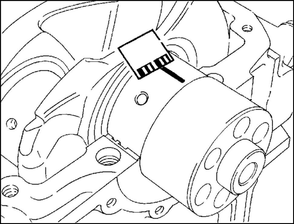
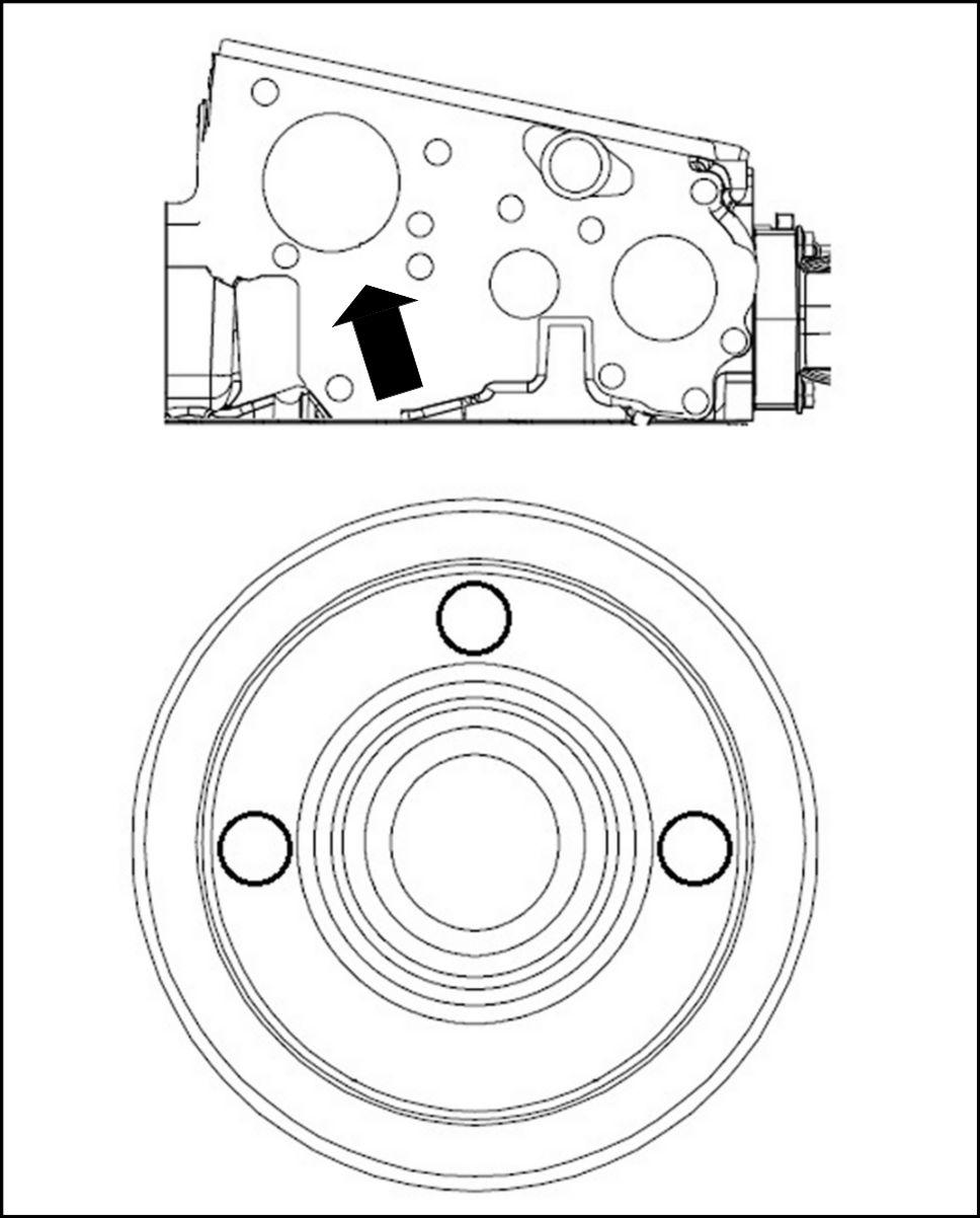
The rear cover oval shape where other Cursor® 9 engines it’ s
The flywheel speed sensor located the right side the others have the left side the
The turbocharger moved higher and toward the center line the Exhaust flap for TIER
RAIL15TR00608GA
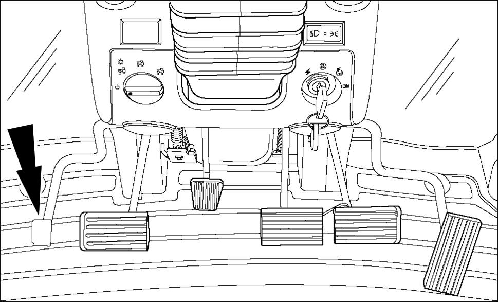
Exhaust brake
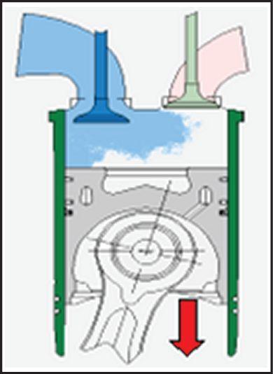
Admission phase:
Intake fresh air
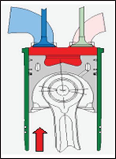
Compression phase:
Energy stored the compressed air , braking fect increases with compression
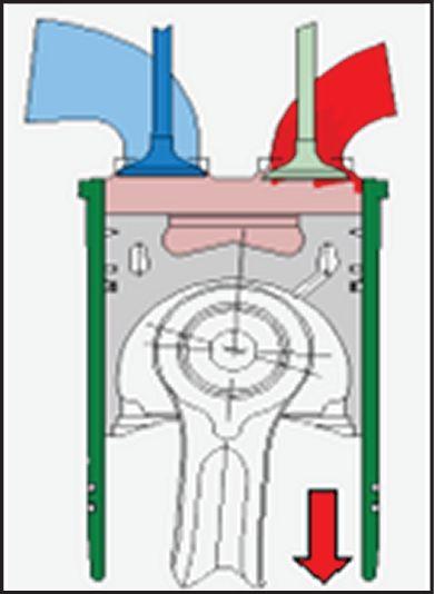
Tdead center:
Exhaust valves compressed air energy blown
All Cursor® engines are equipped with advanced engine brake system: the Iveco T urbo Brake (IBT)
• Decompression engine brake
• Quick responding
• Integrated the engine control
• Linked cruise control
• Linked EBS
Advantage
• Less brake pad wear
• Automatically engaged
Benefit
• Reduced operation cost
• Operator ease
The engine brake controlled the T ractor Control Unit
The Electronic Service T ool (EST) used configure the TCU whether not the tractor has engine
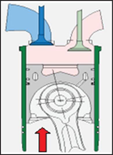
Exhaust phase:
Cylinder empty , energy
Exhaust gases impact against the creating additional braking fect.
The engine brake activated when the pedal left the clutch depressed.
1CCH481AAA 4
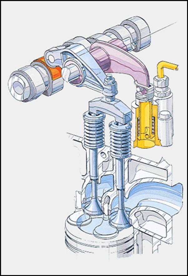
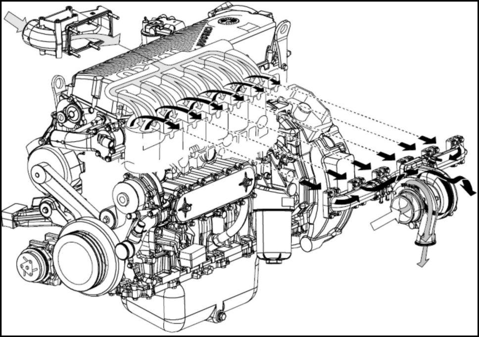
Air Induction - cross flow cylinder head
The cylinder head the cross flow inlet one side and exhaust the other This and four valves per cylinder give excellent breathing ability and ficient perature The air supplied the inlet a gate turbocharger a V ariable Geometry T urbocharger
RAIL15TR00376BA 5
W
astegate turbocharger
The wastegate turbocharger allows for a larger bocharger installed producing higher boost sures the low and midrange rpm while not over - boosting high
Intake pressure builds against a diaphragm the gate and opens a valve allowing exhaust bypass the turbine therefore slowing the compressor and limiting the pressure the intake
RAIL15TR00396BA 6
RCPH1
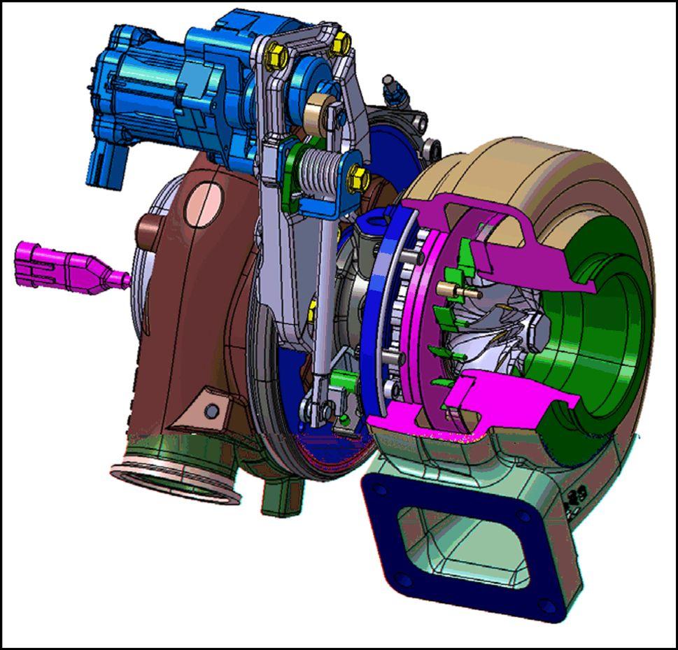
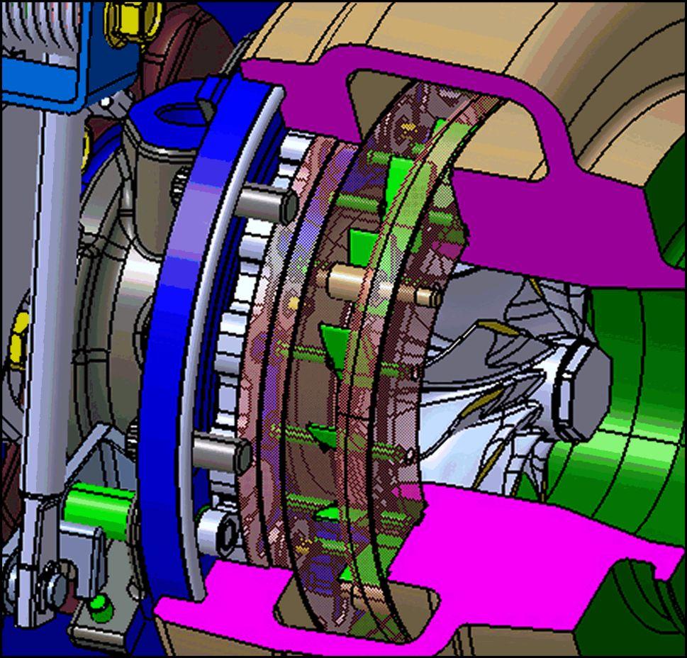
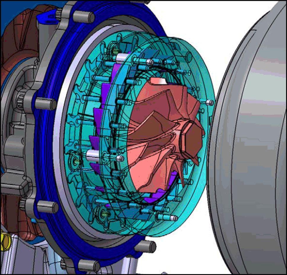
Electronically V ariable Geometry T urbocharger (eVGT)
RAIL15TR00383BA 7
RAIL15TR00395BA 8
V anes open (low boost)
The electronically V ariable Geometry T urbocharger (eVGT) used the TIER and TIER and The eVGT electronically controlled the Engine Control Unit (ECU).
RAIL15TR00394BA 9
boost)
The eVGT uses a series aerodynamic vanes direct exhaust toward the turbine controlling both the velocity and angle the exhaust contacts the This gives the ECU the ability dynamically the boost pressure any given engine speed and Improving performance and fuel economy
Fully open the velocity slows and the angle decreased therefore the turbine and compressor turn slower producing less When the vanes close increasing the velocity and therefore increasing turbine and pressor speed, producing higher boost anytime needed across the entire operating range the
V anes closed (high
EDC17CV41
A
A new Engine Control Unit (ECU) used TIER the used FPT engines from the L NEF the L Cursor® t has two electrical connectors: one for the engine components and one for the tractor connections. Pin connections will common for all the CNH / FPT engines using this controller T ractor connector
Engine connector
The EDC17CV41 controls all engine and Selective Catalytic Reduction (SCR)
RAIL14TR00234P
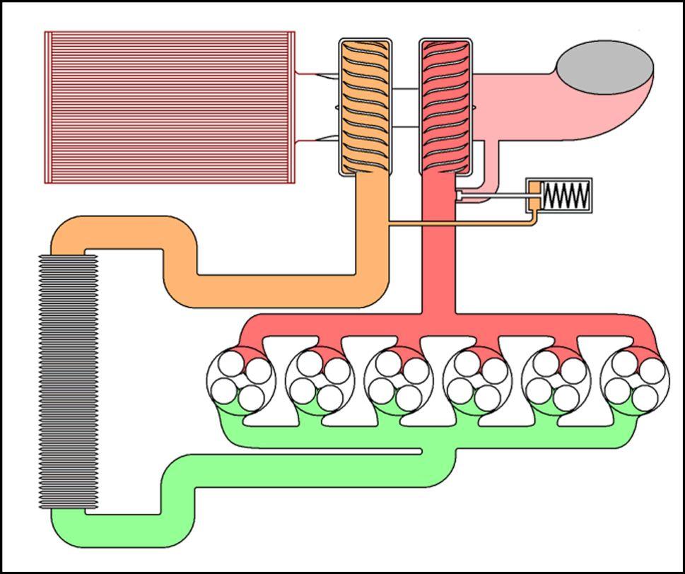
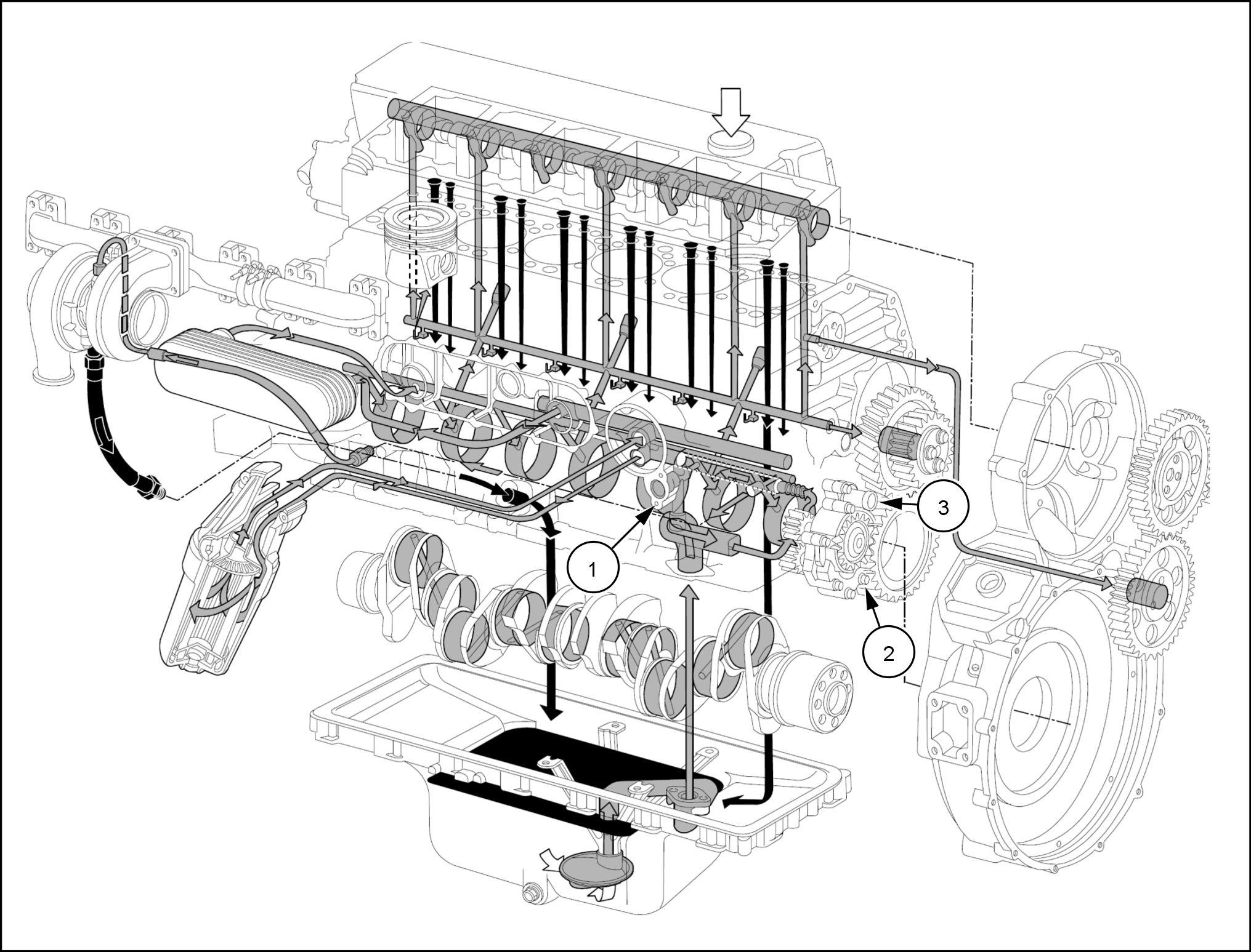
Lubrication System
1 1
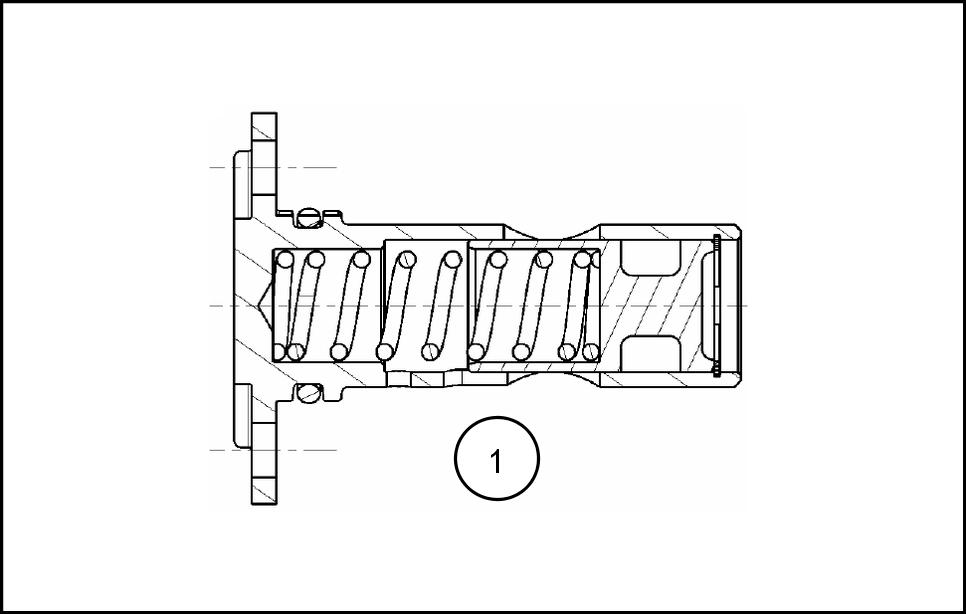
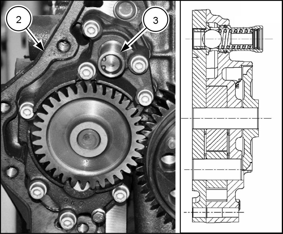
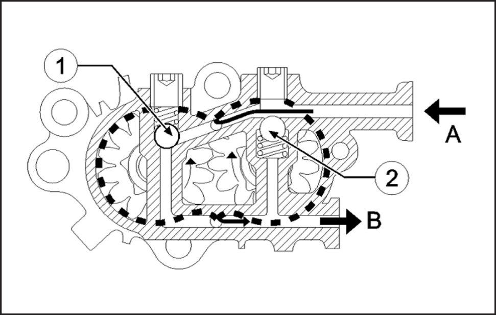
Oil pressure controlled a 5 bar ( 72.5 psi ) relief valve (1) the oil galley coming from the gear type oil pump (2) located behind the rear cover the The oil pump also has over pressurization relief valve (3) set approximately bar ( 145 psi )
A 5 bar ( psi ) oil pressure control valve (1) located the left hand side the The oil pump assembly (2) includes over pressurization relief valve (3) that protects the The valve opens 9.4 –10.8 bar ( 136.3 –156.6 psi ) .
RAIL15TR00416GA
RAIL15TR00367AA
RAIL15TR00389BA
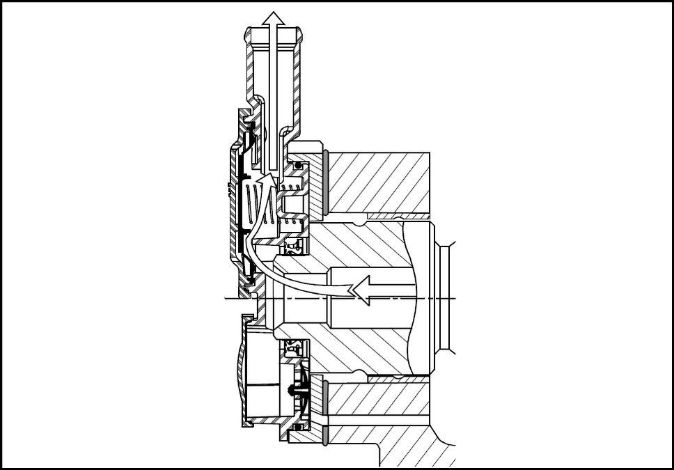
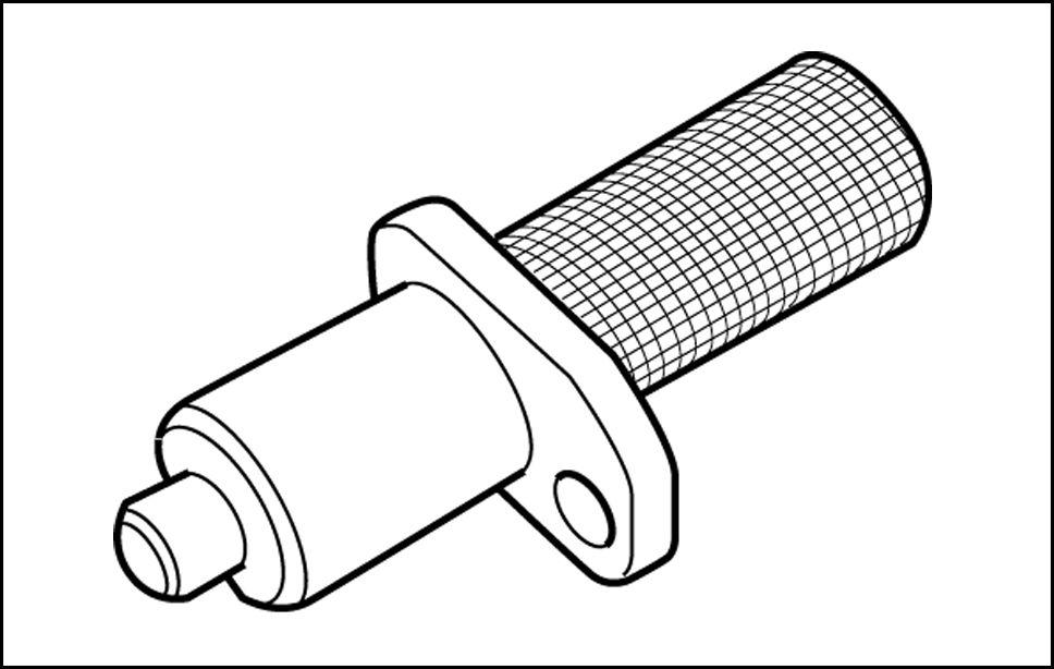
Blow - recirculation
Blow - controlled a rotary filter bolted the rear the As the cam turns excess oil thrown f centrifugal finer oil filtered
The blow - then passes through the center the camshaft and exits the
This filter must replaced regular intervals the gine will build excessive pressure the crank
Built into the cover the front a valve that allows blow - pressures out, but will not allow atmospheric pressure into the
This filtered air directed back into the inlet and -
RAIL15TR00366AA
RAIL15TR00377BA
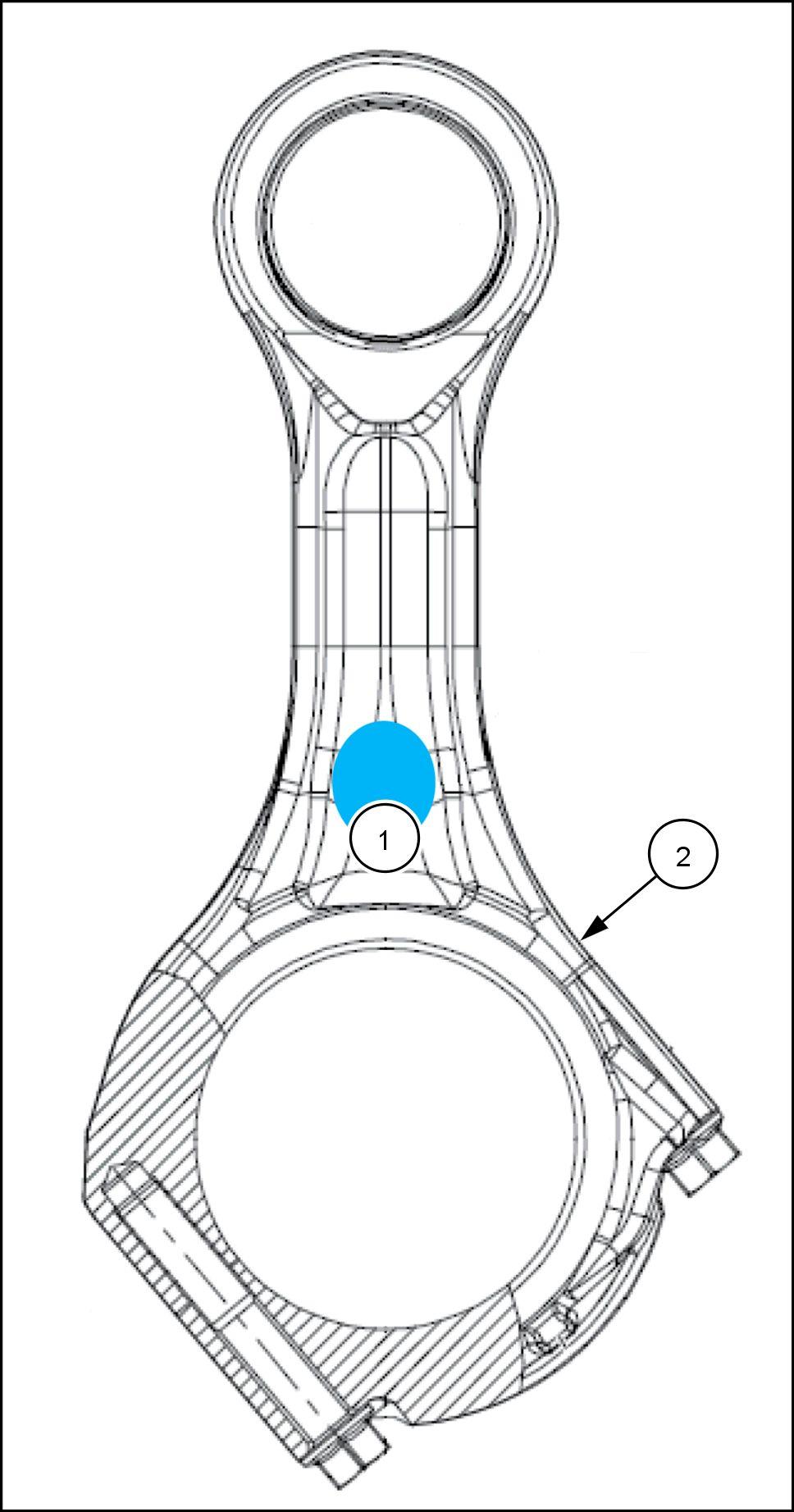
Connecting Rods
Connecting rods must all the same weight class
The weight class identified a color swatch the connecting
There are three classes crankshaft bearing diameters (bore size) the connecting The bore size marked a color code the rod. The oil clearance mined the connecting rod bore size and the crankshaft journal Based connecting rod bore diameter and the crankshaft journal diameter a bearing set must
Connecting rods are the fracture split Care must taken when handling these rods any damage the cap / rod mating area requires that the rod replaced.
Connecting rod class and color Bore diameter and color designation
Y ellow
Green 3450 – 3470 grams
Grade Y ellow
Blue
Y ellow
Green 3471 – 3490 grams
Grade Green
Blue
Y ellow
Green 3491 – 3510 grams
Grade Blue
Blue
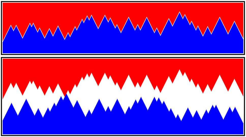
Fracture split rods give nearly perfect both examples the red (rod) profiles are identical are the blue (cap) the top example the rod fits perfectly with the the lower example the rod the same position but the cap here the material peaks align peak peak and keeps cap from mating with the rod.
RAIL15TR00397CA
RAIL15TR00375AA
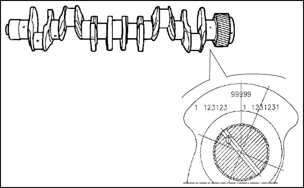
Crankshaft
• The crankshaft are classified three classes: there are three classes for the connecting rod journals and three classes for the main
• The crankshaft journal sizes are stamped the rear flyweight for both the connecting rod journals and the main journals.
• Six digits for the connecting rods and seven digits for the
• The crankshaft may have been grounddersize from the factory A (1) preceding the six digits a standard crankshaft, a (2) preceding for a shaft that has been ground
• The main bearing bores the block are classed 1,2,or 3 and are located the rear the block lower right hand the classifications are not the crankshaft must measured and classified for each
Standard crankshaft connecting rod bearing selection
Standard crankshaft connecting rod journals Class (1) Y ellow paint
Connecting rod bore
Green Green Y ellow Class (1) Green Y ellow Y ellow Red Green Green Class (2) Green Green Y ellow Red Red Green Class (3) Red Green Green
NOTE: may necessary mix two bearing shells one
0.127 under - size crankshaft connecting rod bearing selection
Connecting rod bore0.127 Standard crankshaft connecting rod journals Class (1) Y ellow paint Class (2) Green paint
(3) Blue paint
Green / Black Green / Black Y ellow / Black Class (1) Green / Black Y ellow / Black Y ellow / Black Red / Black Green / Black Green / Black Class (2) Green / Black Green / Black Y ellow / Black Red / Black Red / Black Green / Black Class (3) Red / Black Green / Black Green / Black
Standard crankshaft main bearing selection
Main bearing bore fit class Standard crankshaft
With the variables the bearing selection process, always a good idea use a plastic gauge test each journal for proper
RAIL15TR00392BA
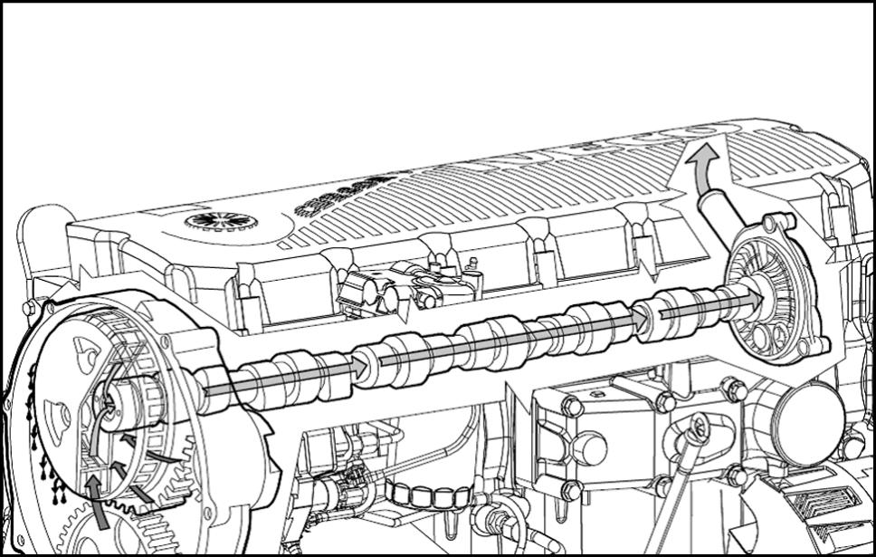
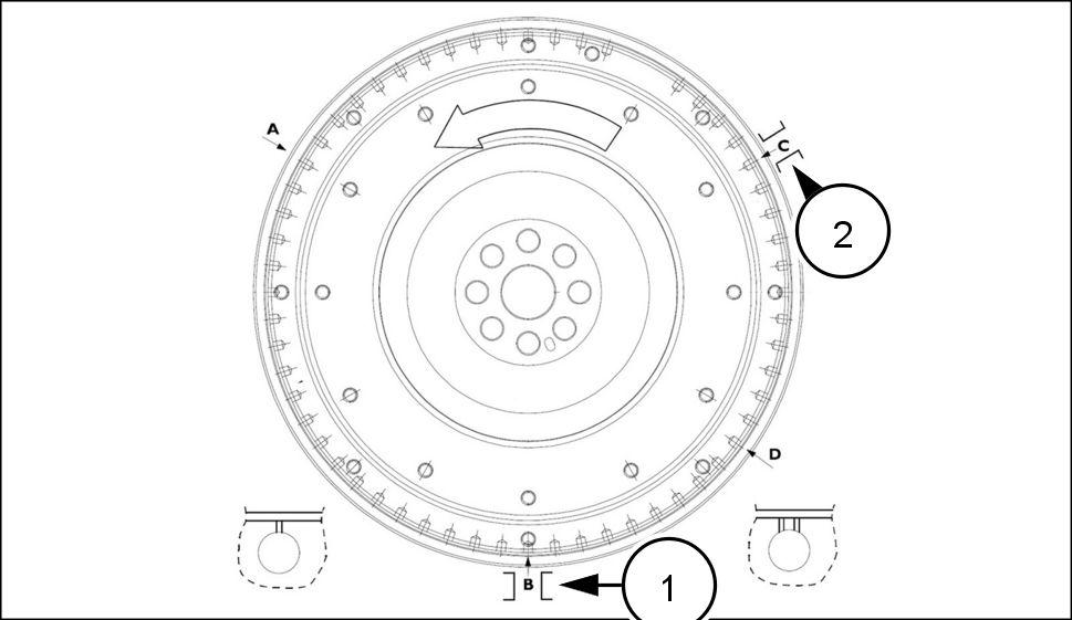
Camshaft installation and timing
When timing adjusting valves critical position the C D holes the center the view hole (1) the bottom the bell Serious engine damage can occur procedures are not followed carefully
TDC 3 and 4
TDC 1 and 6
TDC 2 and 5
° before TDC 1 and 6
When timing adjusting valves critical position the C D holes the center the view hole (1) the bottom the bell Serious engine damage can occur procedures are not followed carefully
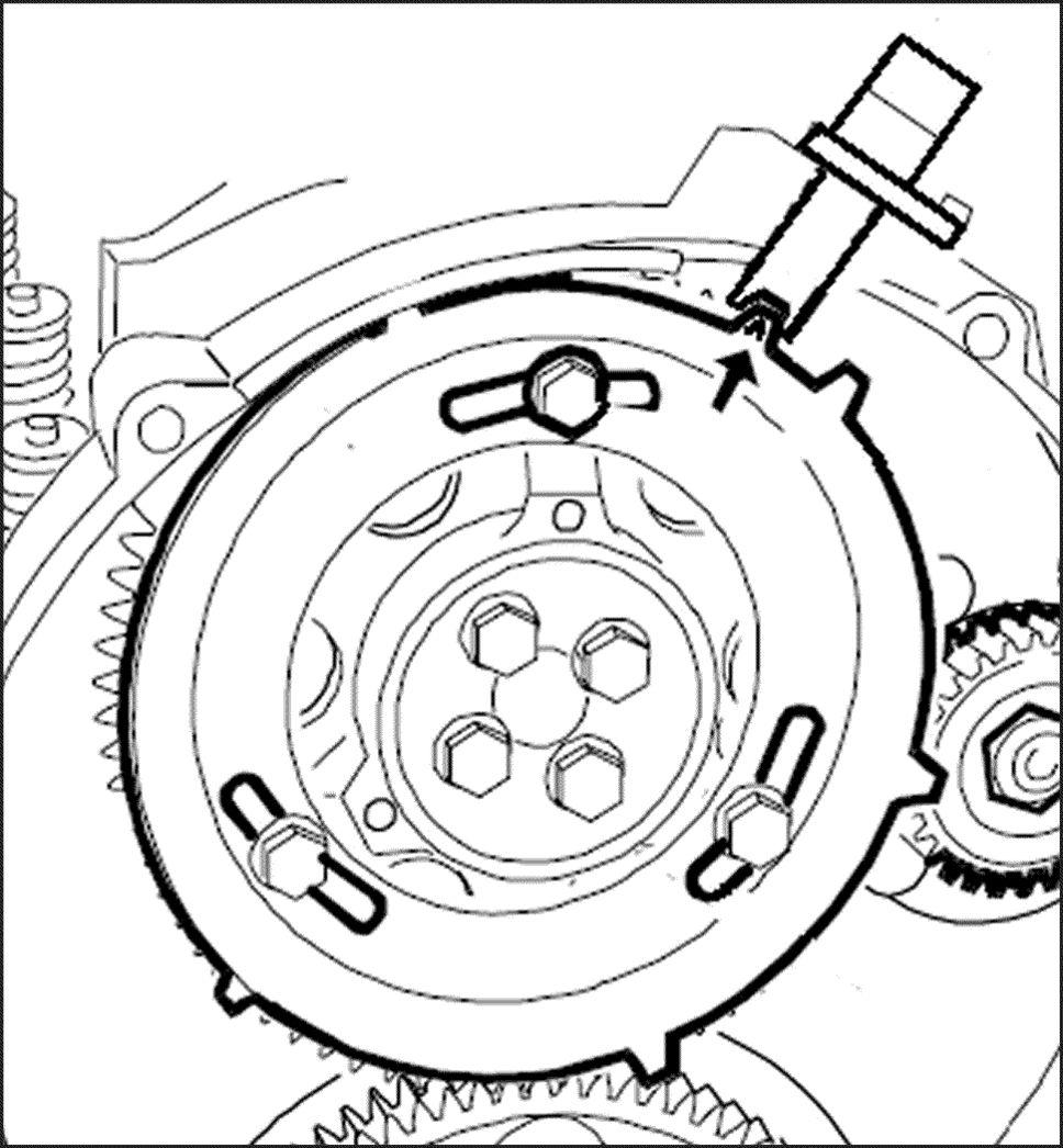
NOTE: All references flywheel rotation will made viewed from the rear the
NOTE: The B and C holes are marked with one hash mark (l) and the hole with two hash marks
Position the flywheel TDC 1 and the B hole the This can done locating the D hole the bottom view hole the bell housing, and then turning the flywheel counterclockwise until the B hole
Once the flywheel this position, should pinned position with the flywheel pinning tool 380000150 the sensor
The engine now ready have the camshaft
RAIL15TR00406F
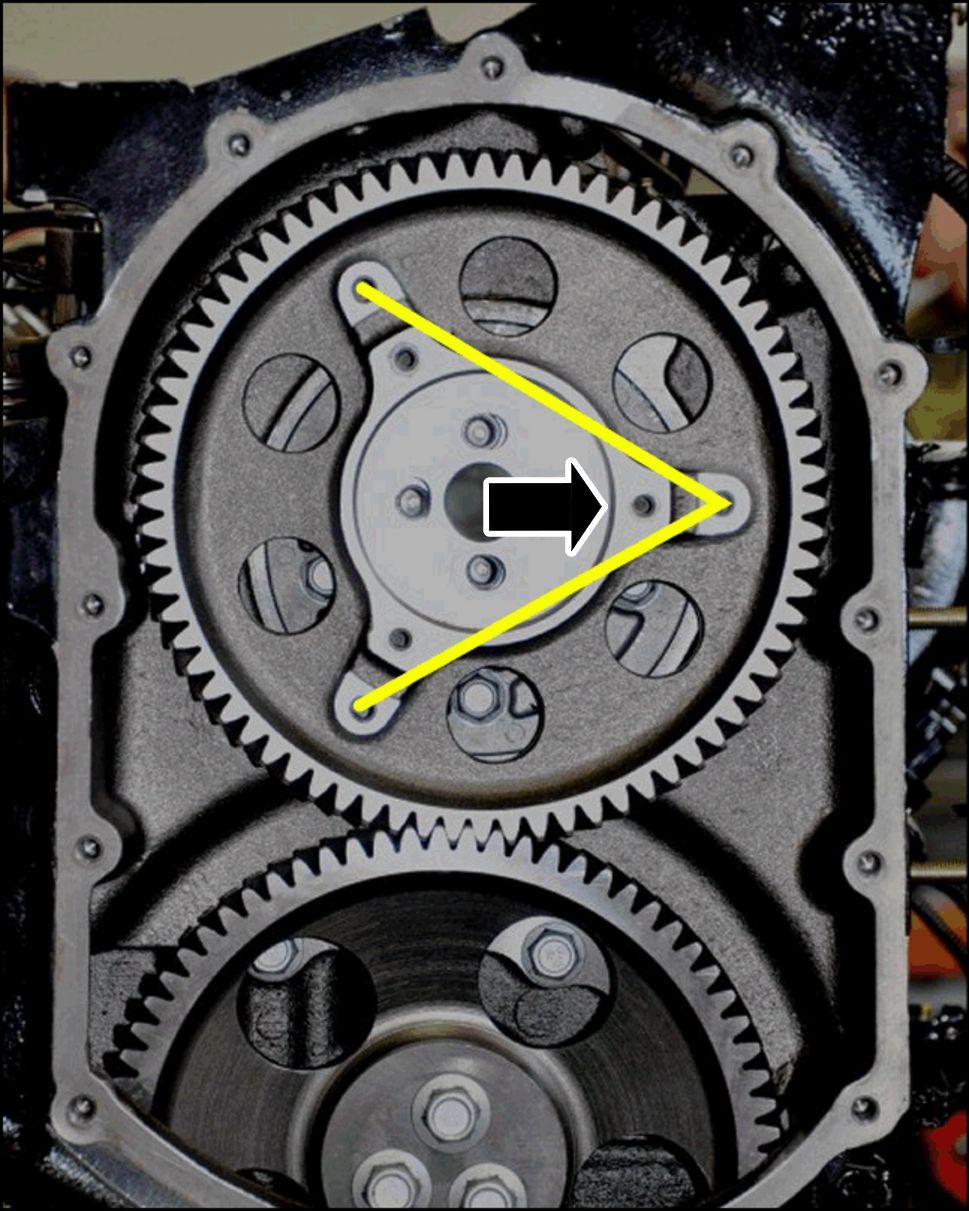
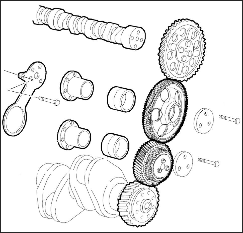
Install the camshaft with the three holes (viewed from the front) the and 3 position.
NOTE: not trust the back the cam for positioning.
Install the camshaft gear shown.
the cam drive must installed with the three phonic wheel mounting holes making arrow pointing the this not the phonic wheel will not able
The slotted holes must centered the camshaft bolt holes make fine adjustments the cam later this
Install the bolts and but not torque yet; they will loosened later this procedure.
RAIL15TR00380BA
RAIL15TR00378BA
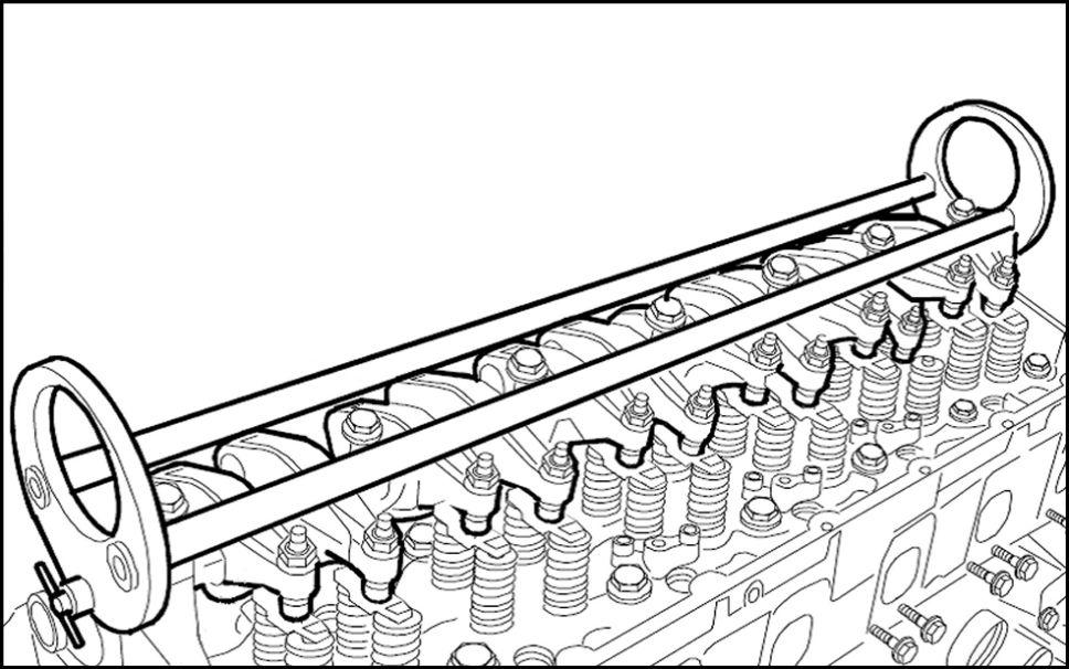
Install the rocker arm shaft assembly using tool number: 380000149 .
Camshaft timing
The double idler gear location The upper single idler gear location can adjusted and used set the back lash between the idler gear and the camshaft gear
This back lash has checked and set since this overhead camshaft All for the gear train mounted the block except the camshaft gear which mounted the cylinder Set the back lash before the rocker arm assembly
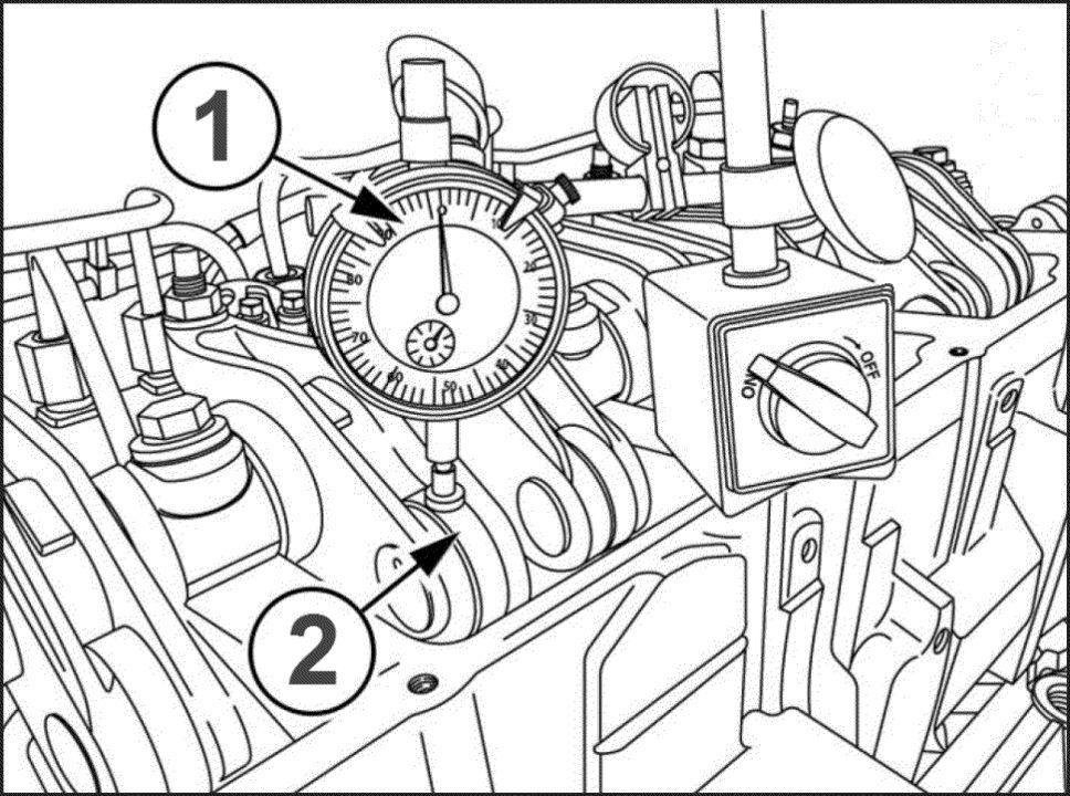
Use a dial indicator measure the camshaft gear idler back Only measure the back lash between the upper idler gear and the camshaft gear . Install the dial indicator tangential a camshaft gear Hold the idler that does not move and rock the camshaft gear
Correct back lash – ( – )
Rotate the flywheel clockwise until the D hole appears the bottom view hole. Install a dial indicator (1) the number 3 exhaust valve rocker arm camshaft roller (2)
Preload the dial indicator ( )
Rotate the engine clockwise until the dial indicator stops moving: lift the valve end the rocker arm take any clearance play out and verify that you are the inner base circle the the lowest
RAIL15TR00374AA
RAIL15TR01370BA
RAIL15TR01371BA
Zero the dial indicator this
T ier III and later Cursor® 9 engines, rotate the engine counterclockwise until the dial indicator reads 5.29 ( ) ± ( ) Check see the D hole the window and that the timing pin will lock the
the D hole not centered the window and the flywheel cannot locked:
Loosen the four bolts that retain the camshaft gear
Rotate the flywheel until the D hole the timing window and the flywheel can T ighten the four bolts that hold the camshaft gear the
Now , verify the timing turning the engine clockwise –° and then back counterclockwise until the D hole the timing window and the timing pin will lock the V erify the reading the dial indicator ( ) ± 0.05 ( 0.002 )
NOTE: For engines without engine brake engine serial numbers 25342 and after , set backlash use 4.70 ( )
NOTE: For engines with without engine brake prior engine serial number set backlash use ( 0.21 )
Repeat the above procedure necessary obtain the specified Once timing within the specified range tighten the camshaft gear retaining bolt specified
Ultimately timing for the cam a TIER 4 engine is: ( ) lift number 3 exhaust rocker arm ° before T Dead Center (TDC) 1 and which the D hole the visible through the hole the bottom the bell housing.
Phonic wheel adjustment
Using the phonic wheel timing fork (special tool 380000151 ) with the flywheel locked the D position, install the phonic wheel the timing fork engages the phonic wheel tooth with the “^” T ighten the phonic wheel retaining bolts the specified
Adjusting the valve lash
• The valves can only adjusted when the piston TDC
• Rotate the engine counterclockwise the B hole (the first hole after the hole with the double Use the timing pin lock the
• Now adjust the valves cylinder number
• Use the chart the left determine which hole use adjust the
RAIL15TR01372BA
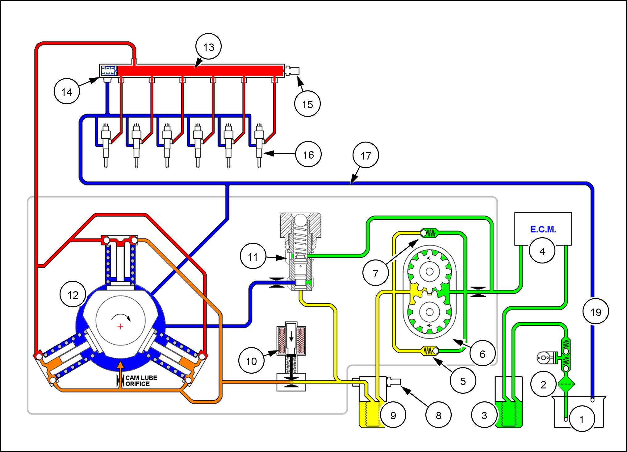
High Pressure Common Rail (HPCR)
Pressure sensor
Common rail
Injector
Supply from high pressure pump
Relief valve
RAIL15TR00407F A
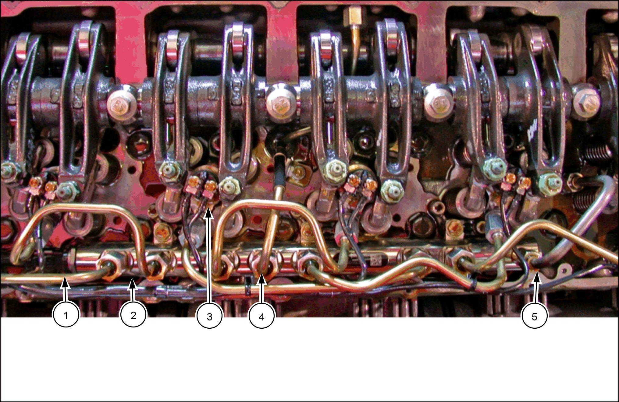
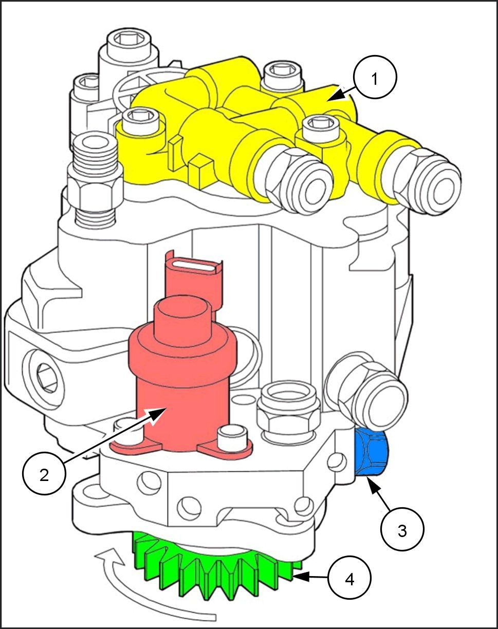
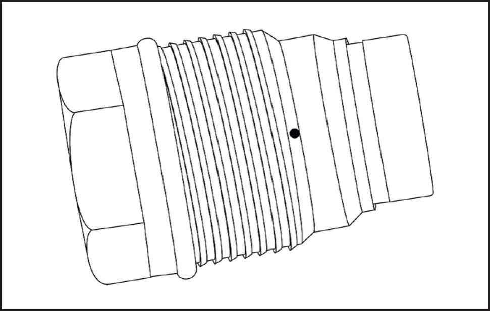
Fuel pump assembly
RAIL15TR00384BA
These are the components the fuel pump that are available separately through parts
Low pressure gear
Regulator valve Controls low pressure supply high pressure the common rail
5.0 bar ( 72.5 psi ) low pressure control valve.
NOTE: There are two 5.0 bar ( 72.5 psi ) pressure valves: one the gear pump and this one the pump body
Drive gear
Fuel system Components
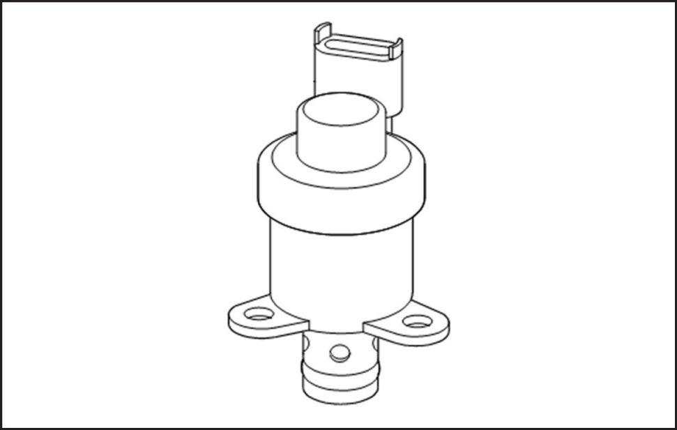
Pressure regulator
Located the high pressure regulates the amount fuel supplied the high pressure pump the basis signals received from the Engine Control Unit (ECU) modulating the dutycycle. This allows pressure variation inside the common
The pressure regulator normally open. The high sure pump therefore maximum delivery mode signal sent the ECU
The regulator Pulse Width Modulated (PWM); ceives V (battery voltage) from the The ECU completes and varies the current controlling the The regulator not polarity Resistance checked should about 3.2 Ω .
Common rail relief valve
The common rail relief valve mounted the end the common rail. functions protect the nents case a failure the rail pressure sensor the pressure regulator that could cause the high pressure pump provide more fuel than the system can safely
The common rail relief valve a two stage valve. When the rail pressure reaches 2000 bar ( 29000 psi ) , the valve opens and will drop the common rail pressure imately 1000 bar ( 14500 psi ) This allows the engine operated but reduced power
Low pressure gear pump
(A) Supply fuel drawn from pre - filter
(B) Supply fuel final filter
(1) Fuel supply relief valve bar ( psi )
(2) Supply pump bypass valve (for bleeding)
The fuel supply transfer pump a gear pump located the back the CP3 high pressure The transfer pump shaft driven f the CP3 high pressure pump shaft.