Link Product I Engine
Market Product Engine
T8.320 PST TIER 4B [ZGRE05001 Europe F2CFE613G*B002
T8.350 PST TIER 4B [ZGREOSOO 1 Europe F2CFE614G*B002
T8.380 PST TIER 4B [ZGREOSOO 1 Eufope F2CFE614D*B002
T8.410 PST TIER 4B [ZGRE05001 Europe F2CFE614C*B002
TB.380 SmartTraxT" PST TIER 4B |ZGRE05001 - ] Europe F2CFE614O*B002
T8.410 SmartTraxT" PST TIER 4B [ZGRE05001 } Europe F2CFE614C*B002
48123726 2\/04/2017
Contents INTRODUCTION Engine...................................................................................................10 [10.001) Engine and crankcase 10.1 [10.101] Cylinaer heads 10.2 [10.202] Air cleaners and lines 10.3 [10.206] Fuel filters................................................................................................................. 10.4 [10.216] Fuel tanks 10.5 [10.218l Fuel injection system................................................................................................ 10.6 [10..304} Engine lubrication system. 10.7 [10.310] Aftercooler. 10.8 [10.400] Engine cooling system............................................................................................. 10.9 [10.414] Fan and drive......................................................................................................... 10.10 [10.500] Selective Catalytic Reduction (SCR) exhaust treatment ........................................ 10.11 Power coupling......................................................................................19 [19.100] Drive shaft. 19.1 [19.110] Flywheel damper 19.2 [19.120] Drive shaft shidld assembly 19.3 Transmission........................................................................................21 [21.105] Powershift transmission hydraulic components........................................................ 21.1 [21.113] Powershift transmission 21.2 [21.135] Powershift transmission external controls 21.3 [21.155] Powershift transmission internal components 21.4 [21.200] Dropbox 21.5 [21.900] Hydraulic pump drive ............................................................................................... 21.6 Four-Wheel Drive (4WD) system...........................................................23 [23.2Ci2) Electro hydraulic control 23.1 48123726 21/04/2017
[23.314] Drive shaft. 23.2 Front axle system 25 [25.100] Powered front axle 25.1 [25.102] Front bevel gear set and differential 25.2 [25.108] Final drive hub, steering knuckles, and shafts 25.3 25.4 Rear axle system..................................................................................27 [27.100] Powered rear axle.................................................................................................... 27.1 [27.106] Rear bevel gear set and differential 27.2 |27.120] Planetary and final drives 27.3 (27.610] Rear axle track yoke assembly 27.4 Power Take-OP (PTO).............................................................................31 |31.104] Rear electro-hydraulic control 31.1 [31.110] One speed rear Power Take Off (PTO) 31.2 |31.114] Two-speed rear Power Take Off (PTO) 31.3 [31.146] Front Power Take Off (PTO) 31.4 Brakes and controls..............................................................................33 [33.110] Parking brake or parking lock 33.1 |33.202] Hydraulic service brakes 33.2 33.220] Trailer brake hydraulic control 33.3 [33.224] Trailer brake pneumatic control........................................................................ 33.4 |33.240] Emergency brake........................................................................................... 33.5 Hydraulic systems................................................................................. 35 [35.000] Hydraulic systems .................................................................................................... 35.1 |35.102] Pump control valves................................................................................................. 35.2 |35.106] Variable displacement pump.................................................................................... 35.3 |35.114] Three-point hitch control valve ................................................................................. 35.4 35.124] Three-point hitch hydraulic adjustment..................................................................... 35.5 48123726 2\/04/2017
[35.204] Remote control valves 35.6 [35.300] Reservoir, cooIer, and fiiters 35.7 [35.304] Combination pump units .............................................................................. 35.8 Hitches, drawbars, and implement couplings.......................................37 [37.110] Rear three-point hitch 37.1 [37.162] Front hitch................................................................................................................ 37.2 Frames and ballasting.......................................................................39 [39.100] Frame 39.1 Steering.......................................................................................... 41 [41.101] Steering control 41.1 [41.200] Hydraulic control components 41.2 [41.206} Pump 41.3 [41.432) Autoguidance steering..............................................................................................41.4 [41.910] Auxiliary steering...................................................................................................... 41.5 Wheels 44 [44.520] Rear wheels 44.1 Tracks and track suspension .......................................................48 [48.10Cl] Tracks 48.1 (48.130] Track frame and driving wheels 48.2 [48.134} Track tension units 48.3 [48.138j Track rollers..............................................................................................................48.4 Cab climate control 50 [50.100} Heating 50.1 [50.200] Air conditioning 50.2 [50.300] Cab pressurizing system 50.3 Electrical systems..................................................................................55 [55.000] Electrical system ...................................................................................................... 55.1 48123726 21/04/2017
[55.010] Fuel injection system.............................................................................................55.2 (55.012] Engine cooling system 55.3 [55.013] Engine oil system..................................................................................................55.4 (55.014] Engine intake and exhaust system ........................................................................55.5 [55.015] Engine control system 55.6 [55.024] Transmission control system 55.7 (55.045] Front axle control system 55.8 (55.047] Steering control system 55.9 [55.050] Heating, Ventilation, and Air-Conditioning (HVAC) control system 55.10 [55.100] Harnesses and connectors...................................................................................55.11 [55.130] Rear three-point hitch electronic control system................................................... 55.12 [55.302] Battery 55.13 [55.408] Warning indicators, alarms, and instruments 55.14 [55.512] Cab controls 55.15 [55.640j Electronic modules 55.16 [55.988] Selective Catalytic Reduction (SCR) electrical system 55.17 [55.DTC] FAULT CODES.................................................................................................. 55.18 Platform, cab, bodywork, and decals ...................................................90 [90.100] Engine hood and panels 90.1 [90.102j Engine shields, hood latches, and trims.................................................................90.2 [90.124] Pneumatically-adjusted operator seat. 90.3 [90.150] Cab 90.4 [90.151] Cab interior 90.5 [90.160] Cab interior trim and panels...................................................................................90.6 48123726 Z1/04/2017

INTRODUCTION 48123726 21/04/2017 1
Contents INTRODUCTION Foreword - Important notice regarding equipment servicing 3 Safety rules ............................................................................................................................4 Safety rules - General maintenance safety 5 Safety rules Personal Protective Equipment (PPE)................................................................6 Safety rules - Do Not Operate tag Safety rules - Ecology and the environment..............................................................................8 Torque - Minimum tightening torques for normal assembly 9 Torque - Standard torque data for hydfaU[ic connections 14 General specification - Engine...............................................................................................21 General specification - Power train 22 Capacities 25 Product identification 26 Product identification Machine orientation 29 48123726 2T/04/2017 2
Foreword - Important notice regarding equipment servicing
All repair and maintenance worI‹ listed in this manual must be carried out only by qualified dealership personnel, strictly complying with the instructions given, and using, whenever possible, the special tools.
Anyone who performs repair and maintenance operations without complying with the procedures provided herein shall beresponsible for any subsequent damages.
The manufacturer and all the organizations of its distribution chain, including - without limitation - national, regional, or local dealers, reject any responsibility for damages caused by parts and/or components not approved by the manufacturer, including those used for the servicing or repair of the produQ manufactured or marketed by the manufaQurer. In any case, no warranty is given or attributed on the product manufactured or marketed by the manufacturer in case of damages caused by parts and/or components not approved by the manufacturer.
The manufacturer reserves the right to make improvements in design and changes in specifications at any time without notice and without incurring any obligation to install them on units previously sold. Specifications, descriptions, and illustrativematerial hereinare asaECrlrate asknown st time ofpublfCdtiOf\ but are subject to chBnge without notice. In case of questions, refer to your NEWHOLLAND Sales and Service Networks.
INTRODUCTION
48123726 21/04/2017
Safety rules
Personal safety
Thisisthe safety alert symbol. It isused to alert youto potential personal injury hazards. Obey all safety messages that follow this symbol to avoid possible death or injury.

Throughout this manual you will find the signal words DANGER, WARNING, and CAUTION followed by special instructions. These precautions are intended for the personal safety of you andthose working with you.
Read and understand all thesafety messages inthis manual before you operate or service the machine.
DANGER indicates a hazardous situation that, if not avoided, will result in death or serious injury.
WARNING indicates a hazardous situation that, ifnot avoided, could result in death or serious injury.
CAUTION indicates a hazardous situation that, if not avoided, could result inminor ormoderate injury.
Machine safety
fiIOTtCE: Notice indicates a s”ituation that, if not avoided, could resutt in machine or property damage.
Throughout this manual you will find the signal word Notice followed by special instructions to prevent machine or property damage. The word Notice is used to address practices not related to personal safety.
Information
/OTE: Note indicates additional infonnation that c/a/i//es steps, procedures, or other information in this manual.
Throughout this manual you will find the word Note followed by additional information about a step, procedure, or otherinformation in the manual. The word Note isnot intended to address personal safety or property damage.
INTRODUCTION
FAILURE TO FOLLOW DANGER, WARNING, AND CAUTION MESSAGES COULD RESULT IN DEATH OR SERIOUS INJURY.
481Z3726 Z1/04/2017 4
Safety rules - General maintenance safety
General maintenance safety
Keep the area used for servicing the machine clean and dry. Clean up spilled ftuids. Service the machine onafirm, level surface. Install guards and shields after you service the machine. Close all access doors and install all panels after servicing the machine.
Donotattempt toclean, lubricate, clear obstructions, ormake adjustments tothe machine whileitisinmotion or while the engine is running.
Always make sure that working area is clear of tools, parts, other persons and.pets before you start operating the machine.
Unsupported hydraulic cylinders can lose pressure and drop theequipment, causing acrushing hazard. Donot leave equipment in a raised position while parked or during service, unless the equipment is securely supported.
Jack or lift the machine only at jack or lift points indicated in this manual.
Incorrect towing procedures can cause accidents. When you tow a disabled machine follow the procedure in this manual. Use only rigid tow bars.
Stop the engine, remove the key, and relieve pressure before you connect or disconnect fluidlines. Stop the engine and remove the key before you connect or disconnect electrical connections.
Scalding can result from incorrect removal of coolant caps. Cooling systems operate under pressure. Hot coolant can spray out if you remove a cap while the system is hot. Allow the system to cool before you remove the cap. When youremove the cap, turn it slowty to allow pressure to escape before you completely remove the cap.
Replace damaged or wom tubes, hoses, electrical wiring, etc.
The engine, transmission, exhaust components, and hydraulic lines may become hot during operation. Take care when you service such components. Allow surfaces to cool before you handle or disconnect hot components. Wear protective equipment when appropriate.
When welding, follow the instructions in the manual. Always disconnect the battery before you weld on the machine. Always wash your hands aRer you handle battery components.
INTRODUCTION
48123726 21/04/2017
SERVICE MANUAL
Engine
T8.320 PST TIER 4B [ZGRE05001 - ], T8.350 PST TIER 4B [ZGRE05001 -
l. TO.380 PST TIER 4B [ZGRE05001 - ], T8.380 SmartTraxTM PST TIER 4B [ZGRE05001 - ], T8.410 PST TIER 4B [ZGRE05001 - ], T8.410 SmartTraxTM PST TIER 4B [ZGRE05001 - ]
48123726 21/04/2017 10
Engine - Overview
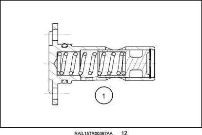
The CursoñB 9
The Cursors 9 is a state of the art engine developed by Fiat Powertrain Technologies (FPT) The Cursoro 9 used in the T8. tractors has some significant internal and external differences from Cursor‹B 9 engines used in other CNH products. There are procedures specific to the T8. engines that are different from the Cursors 9 used in other CNH applications. These changes were made to fit the engine into the T8. series frames without losing our featured visibility around the hood and chassis.
The CursorG• 9 engine was introduced in the CNH combines in 2006 and migrated into the T9. series tractors. It has proven itself to be a consistent reliable performer. The introduction in the T8. series brings it to new heights with up to 275 kW {374Hp) (rated) and 316 kW (429 Hp) in power boost mode.
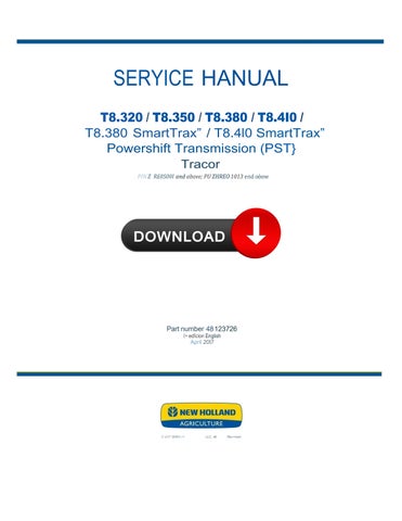
• 6 cylinder, 24 valve, turbocharged and aftercooled
• Single overhead cam with roller rocker arms
• Wastegate turbo/Electronic Variable Geometry Turbocharger (EVGT)
• High pressure common rail fuel system
• Selective Catalytic Reduction (SCR) emissions control
• TIER 4B compliant without internal or external Exhaust Gas Recirculation (EGR)
48123726 21/04/2017 10.1 [10.001] / 3
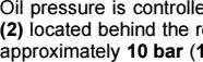
Visual external differences for T8. tractor englnes
There are a few things that make the FPT CursorD• 9 engine used in the T8. tractors visually and mechanically different from other CursorB 9 applications.
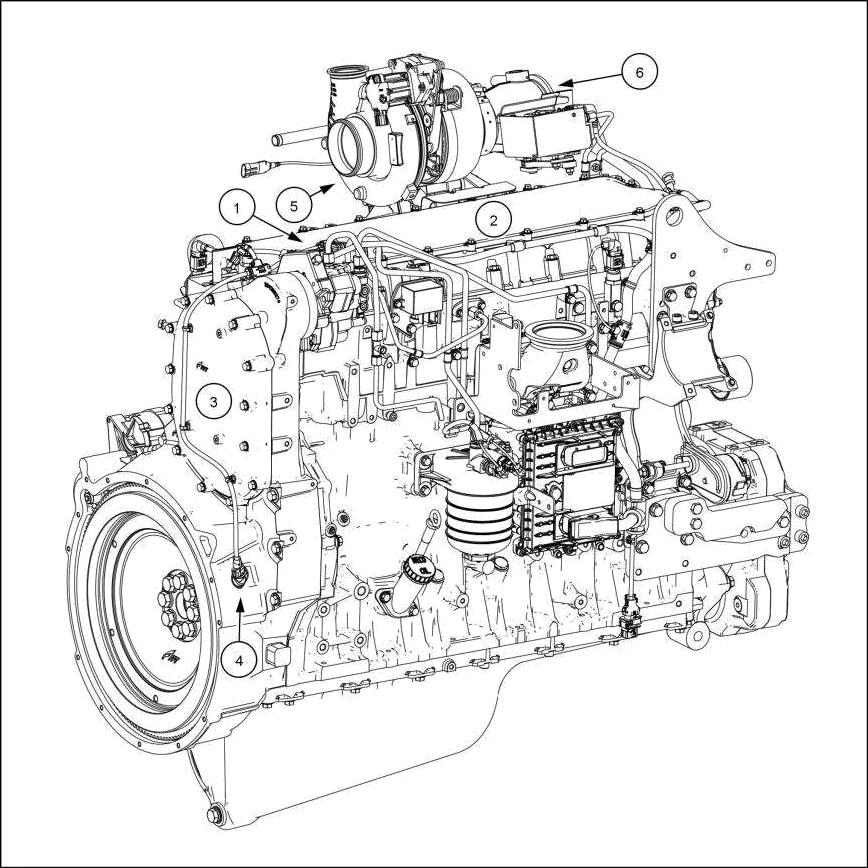
1. The fuel pump sits higher and closet to the center line of the engine.
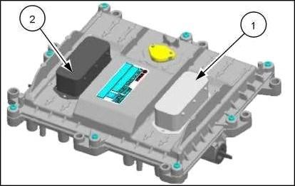
2. A two piece valve cover assembly that allows for valve adjustment without removing the entire cover.
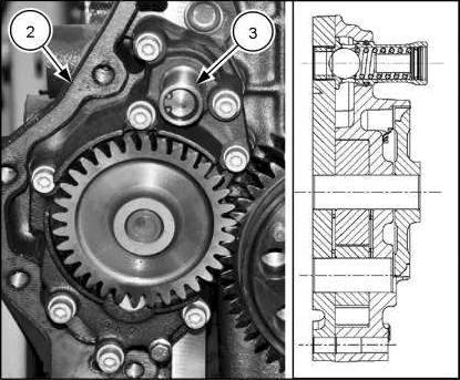
3. The rear cover is an oval shape where on other CursoñB 9 engines it's round.
4. The flywheel speed sensor is located on the right side of the engine, others have on the left side of the engine.
5. The turbocharger is moved higher and toward the center line of the engine.
6. Exhaust ftap for TIER 4B.
Engine - Engine and crankcase
48123726 21/04/2017 10.1 [10.001] / 5
Engine - Engine and crankcase


The engine brake is activated when the pedal left of the clutch is depressed.
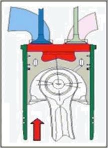
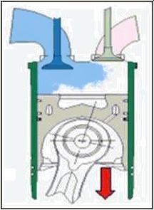
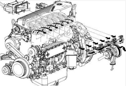
Air Induction - cross flow cylinder head
The cylinder head is of the cross flow design, inlet on one side and exhaust on the other. This and four valves per cylinder give it excellent breathing ability and efficient temperature control. The air is supplied to the inlet by a wastegate turbocharger or a Variable Geometry Turbocharger (VGT).
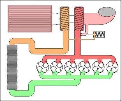
Wastegate turbocharger
The wastegate turbocharger allows for a larger tur bocharger to be installed producing highef boost pressures in the low and midrange rpm while not over-boosting at high rpm.
Intake pressure builds against a diaphragm in the wastegate and opens a valve allowing exhaust to bypass the turbine therefore slowing the compressor and limiting the pressure in the intake manifold.
’ . ..
48123726 21/04/2017 10.1 |10.001] / 7
Electronically Variable Geometry Turbocharger (eVGT)
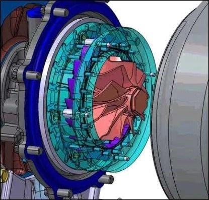
The electronically Variable Geometry Turbocharger (eVGT) is used on the TIER 4A T8.420 and TIER 4B T8.350, T8.380, T8.410 and T8.435. The eVGT is electronically controlled by the Engine Control Unit (ECU).
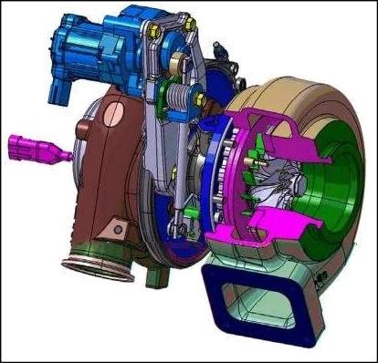
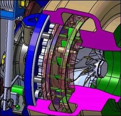
The eVGT uses a series of aerodynamic vanes to direct exhaust toward the turbine controlling both the velocity and angle the exhaust contacts the turbine. This gives the ECU the ability to dynamically lune" the boost pressure at any given engine speed and load, Improving performance and fuel economy.
Fully open the velocity slowsand the angle is decreased therefore the turbine and compressor turn slower producing less boost. When needed, the vanes close increasing the velocity and angle, therefore increasing turbine and compressor speed, producing higher boost anytime it is needed across the entire operating range of the engine.
Engine - Engine and crankcase
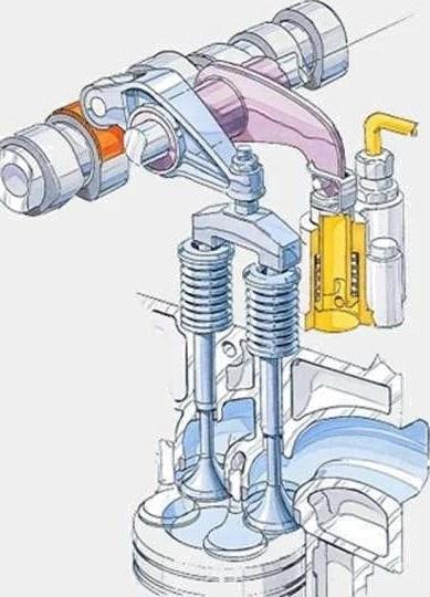
Vanes open (low boost)
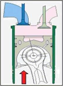
Vanes closed (high boost)
48123726 2J/04/2017 10.1 |10.001] / 8
EDC17CV41