This Workshop Manual has been prepared to provide servicing personnel with information on the mechanism, service and maintenance of M5040, M6040 and M7040. It is divided into three parts, “General”, “Mechanism” and “Servicing”.
■ General Information on the tractor identification, the general precautions, maintenance check list, check and maintenance and special tools are described.
■ Mechanism
Information on the construction and function are included. This part should be understood before proceeding with troubleshooting, disassembling and servicing.
Refer to Diesel Engine / Tractor Mechanism Workshop Manual (Code No. 9Y02101874 / 9Y021-18201) for the one which has not been described to this workshop manual.
■ Servicing
Information on the troubleshooting, servicing specification lists, tightening torque, checking and adjusting, disassembling and assembling, and servicing which cover procedures, precautions, factory specifications and allowable limits.
All information illustrations and specifications contained in this manual are based on the latest product information available at the time of publication.
The right is reserved to make changes in all information at any time without notice.
Due to covering many models of this manual, information or picture being used, have not been specified as one model.
May 2006
0 KUBOTA Corporation 2006
M5040, M6040, M7040, WSM
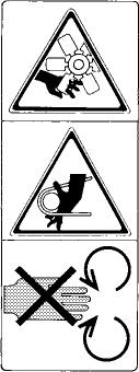
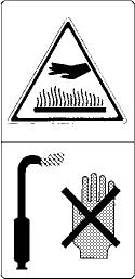
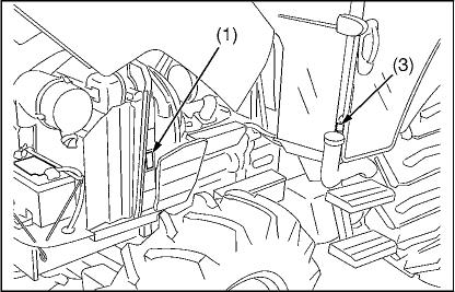
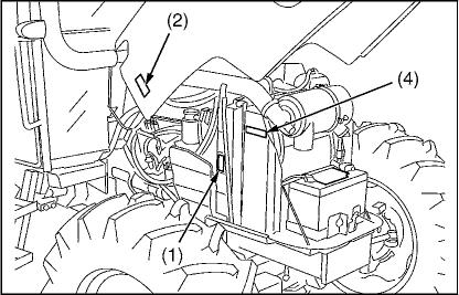
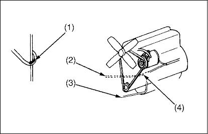
■ CABIN Model
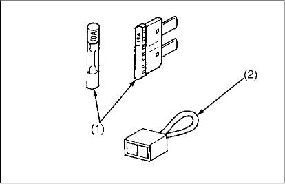
(1) Part No. 6C090-4958-2 Stay clear oÏ engine fan and fanbelt.
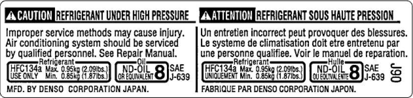
(4) Part No. 3A851-7295-1
M7040 Kubota Repair Manual - DOWNLOAD
SAFETY INSTRUCTIONS
(2) Part No. 3N300-4958-1
Donot touch hot surface like muffler, etc.
(3) Part No. 6C040-4741-1 No Ïire
Improper service msthods oiay' csuse In)ury. AiF ¢00diti0l1i0g SySt8M ShOUId beS8/V1ù0d by qualifi pe nnel. See Repair Manual. Î J-639 MFD. BY DENSO C0RP0RATi0N JAPAN.
Un entreóen incorreNpelit pr0v0quer des blessures. L6 Sy5tefrle de CIifÏI3t1sdti0I1d01 ett6 6l›tr9teriu paF ü09 perS0n0e q‹I81itt00. V0(r I9 Ma0uel de fepartti0fl.
FABRIQUE PA9 DEÏOO C0kP0RkTl0N JAPON.
3TMACAPCP005A
M7040 Kubota Repair Manual - DOWNLOAD
(”U| 0*£7) 0JtJ 098L
’U!ź’ŹgOt6’S9
u08ZtOt0Z# [0#0ZN'0#09N]
t™!LI9 l0’ZSl
**0dt T0Jtt [0#0SN)
(”U!8”69 ’6“SS) 089I ‘08#L TO/\/\t4
( u!‹” Ę/ OȚ 6”Ssł ++ oz8I I OSI’r [avz]
(”u!o”‹sł o‹rz [or0‹IN]
(*U! 0 Z6) +^ 09t’õ [0t’09IN)
(*U!0”96) OJOJ 0ZJrZ [OJrOgłN)
(”U| 0*£Z) tJJtJł 098L
(”U!Z”Z9 I 6”5S)
*'*0 o 0 [0 0 N'0 09N1
(U?ź9Oł0’ZS)
*0ZI¿O¡0BtŁ[0#0SM]
('U! 9”00í) OJOJ gg9g l0tr09ł/\I)
M5040, M6040, M7040, WSM
1. TRACTOR IDENTIFICATION
[1] MODEL NAME AND SERIAL NUMBERS
(1) ROPS Model
3TMACAP0P001A
3TMACAP0P002A
3TMACAP0P003A ° O (1)
When contacting your local KUBOTA distributor, always specify engine serial number, tractor serial number and hourmeter reading. (1) Tractor Identification Rate (4) ROPS IdentificationPlate (2) Tractor Serial Number (ROPS Serial Number) (3) Engine Serial Number
W1030262
3TMACAP0P004A ,L,
J,
M5040, M6040, M7040, WSM
M7040 Kubota Repair Manual - DOWNLOAD
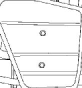
(2) CABIN Model G GENERAL
3TMACAP0P005A
3TMACAP0P006A
When contacting your local KUBOTA distributor, always specify engine serial number, tractor serial number and hourmeter reading. (1) Tractor Identification Plate (3) Tractor Serial Number (2) CABIN Identification Plate (4) Engine Serial Number (CABIN Serial Number)
W1030474
3TMACAP0P007A
3TMACAP0POß8A
M5040, M6040, M7040, WSM
M7040 Kubota Repair Manual - DOWNLOAD
Engine Serial Number
The engine serial number is an identified number for the engine. It is marked after the engine model number. It indicates month and year of manufacture as follows. Year of manufacture
3TMACAN0P013B s| !, e c
Month Engine Serial Number 0001 9999
January A0001 A9999 B0001
February C0001 C9999 D0001
March E0001 E9999 F0001
April G0001 G9999 H0001
May J0001 J9999 K0001
June L0001 L9999 M0001
July N0001 N9999 P0001
August Q0001 Q9999 R0001
September 50001 59999 T0001
October U0001 U9999 V0001
November W0001 W9999 X0001
December Y0001 Y9999 Z0001
e.g. V3007-6A0001
“6" indicates 2006 and “A" indicates January. So, 6A indicates that the engine was manufactured on January, 2006.
(1) Engine Model and Serial Number
W1010477
M5040, M6040, M7040, WSM
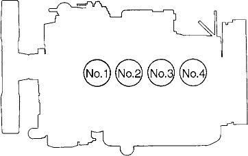
[2] CYLINDER NUMBER
3EEABAB1P011A
The cylinder numbers of KUBOTA diesel engine is designated as shown in the figure.
The sequence of cylinder numbers is given as No.1, No.2, No.3 and No.4 starting from the front cover side.
W1011077
2. GENERAL PRECAUTIONS
• During disassembly, carefully arrange removed parts in a clean area to prevent confusion later. Screws, bolts and nuts should be installed in their original position to prevent reassembly errors.
• When special tools are required, use KUBOTA genuine special tools. Special tools which are not frequently used should be made according to the drawings provided.
• Before disassembling or servicing electrical wires, always disconnect the ground cable from the battery first.
• Remove oil and dirt from parts before measuring.
• Use only KUBOTA genuine parts for parts replacement to maintain machine performance and to assure safety.
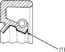
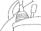
• Gaskets and O-rings must be replaced during reassembly. Apply grease to new O-rings or oil seals before assembling. See the figure left side.
• When reassembling external snap rings or internal snap rings, they must be positioned so that sharp edge faces against the direction from which a force is applied. See the figure left side.
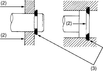
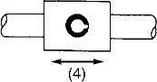
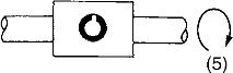
• When inserting spring pins, their splits must face the direction from which a force is applied. See the figure left side.
• To prevent damage to the hydraulic system, use only specified fluid or equivalent.
(1) Grease (2) Force (3) Sharp Edge (4) Axial Force (S) Rotating Movement
(A) External Snap Ring
(B) Internal Snap Ring
W1010904
3TMABAB0P005A
3. HANDLING PRECAUTIONS FOR ELECTRICAL PARTS AND WIRING
3TMABAB0P006A
To ensure safety and prevent damage to the machine and surrounding equipment, heed the following precautions in handling electrical parts and wiring.
■ IMPORTANT
• Check electrical wiring for damage and loosened connection every year. To this end, educate the customer to do his or her own check and at the same time recommend the dealer to perform periodic check for a fee.
• Do not attempt to modify or remodel any electrical parts and wiring.
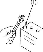
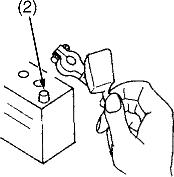
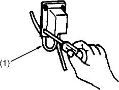
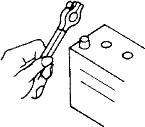
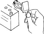
• When removing the battery cables, disconnect the negative cable first. When installing the battery cables, connect the positive cable first.
(1) Negative Terminal (2) Positive Terminal
WIRING
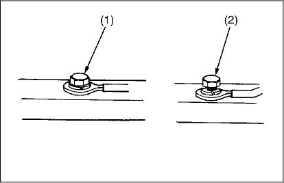
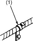
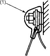
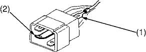
• Securely tighten wiring terminals.
(1) Correct (2) Incorrect
W1011114 (Securely Tighten) (Loosening Leads to Faulty Contact)
W1011216
3TMABAB0P007A
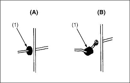
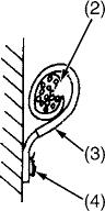
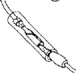
• Do not let wiring contact dangerous part. (1) Dangerous Part (3) Wiring (Correct) (2) Wiring (Incorrect) (4) Dangerous Part
W1011313
3TMABAB0 P008A
3GFABAB0P003A
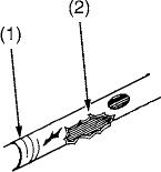
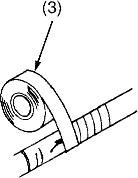
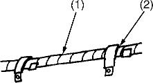
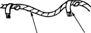
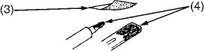
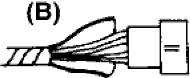
• Repair or change torn or aged wiring immediately. (1) Aged (3) Insulating Vinyl Tape (2) Torn
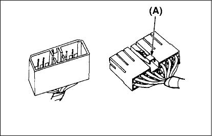
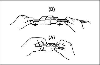
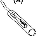
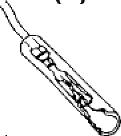
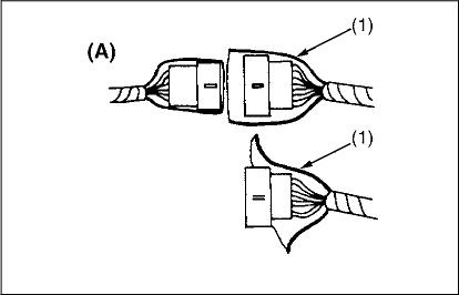
• Make certain that there is no female connector being too open. (A) Correct (B) Incorrect
W1012430
• Make certain plastic connector. (1) Cover is large enough to cover whole (A) Correct (B) Incorrect
W1012519
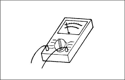
[5] HANDLING OF CIRCUIT TESTER
• Use tester correctly following manual provided with tester.
• Check for polarity and range.
W1012684
3TMABAB0 P020A
4. LUBRICANTS, FUEL AND COOLANT
1 Fuel tank
2 Coolant
tank
3 Washer liquid
4 Engine crankcase (with filter)
L 18.5 U.S.gals. 15.4 Imp.gals.
L
No. 2-D diesel fuel
No. 1-D diesel fuel if temperature is below 10 °C (14 °F)
Fresh clean water with anti-freeze
Automobil washer liquid
API Service Classification CD, CE or CF
Below 0 °C (32 °F): SAE10W, 10W-30 or 10W-40
0 to 25 °C (32 to 77 °F): SAE20, 10W-30 or 10W-40
Above 25 °C (77 °F): SAE30, 10W-30 or 10W-40
KUBOTA SUPER UDT fluid*
6 Front differential case oil [4WD model]
Front axle gear case oil (one side) [4WD model]
L 3.2 U.S.qts. 2.6 Imp.qts.
* KUBOTA original transmission hydraulic fluid.
KUBOTA SUPER UDT fluid or SAE80, SAE90 gear oil
■ NOTE
• Engine Oil : Oil used in the engine should have an American Petroleum Institute (API) service classification and Proper SAE Engine Oil according to the ambient temperature as shown above. Do not mix different brands together.
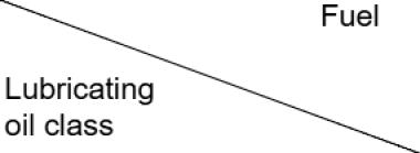
• With the emission control now in effect, the CF-4 and CG-4 lubricating oils have been developed for use of a low-sulfur fuel on-road vehicle engines. When an off-road vehicle engine runs on a high-sulfur fuel, it is advisable to employ the CF, CD or CE lubricating oil with a high total base number. If the CF-4 or CG4 lubricating oil is used with a high-sulfur fuel, change the lubricating oil at shorter intervals.
• Lubricating oil recommended when a low-sulfur or high-sulfur fuel is employed. Fuel
Lubricating oil class
U : Recommendable X : Not recommendable
• Transmission Oil : The oil used to lubricate the transmission is also used as hydraulic fluid. To insure proper operation of the hydraulic system and complete lubrication of the transmission, it is important that a multi-grade transmission fluid be used in this system. We recommend the use of KUBOTA SUPER UDT fluid for optimum protection and performance. Do not mix different brands together.
• Indicated capacity of water and oil are manufacture's estimate.
5. TIGHTENING TORQUES
Screws, bolts and nuts whose tightening torques are not specified in this Workshop Manual should be tightened according to the table below.
[1] GENERAL USE SCREWS, BOLTS AND NUTS
Indicason
(16 mm, 0.63 in.)
(18 mm, 0.71 in.)
[2] STUD BOLTS
Material ofopponent
[3] HYDRAULIC FITTINGS
■ Hydraulic Hose Fittings
■ Hydraulic Pipe Cap Nuts W1014711
■ Adaptors, Elbows and Nipples
POB-PF (Elbow with 0-ring and no nut)
Adaptor (NPT]
M7040 Kubota Repair Manual -
M7040 Kubota Repair Manual - DOWNLOAD
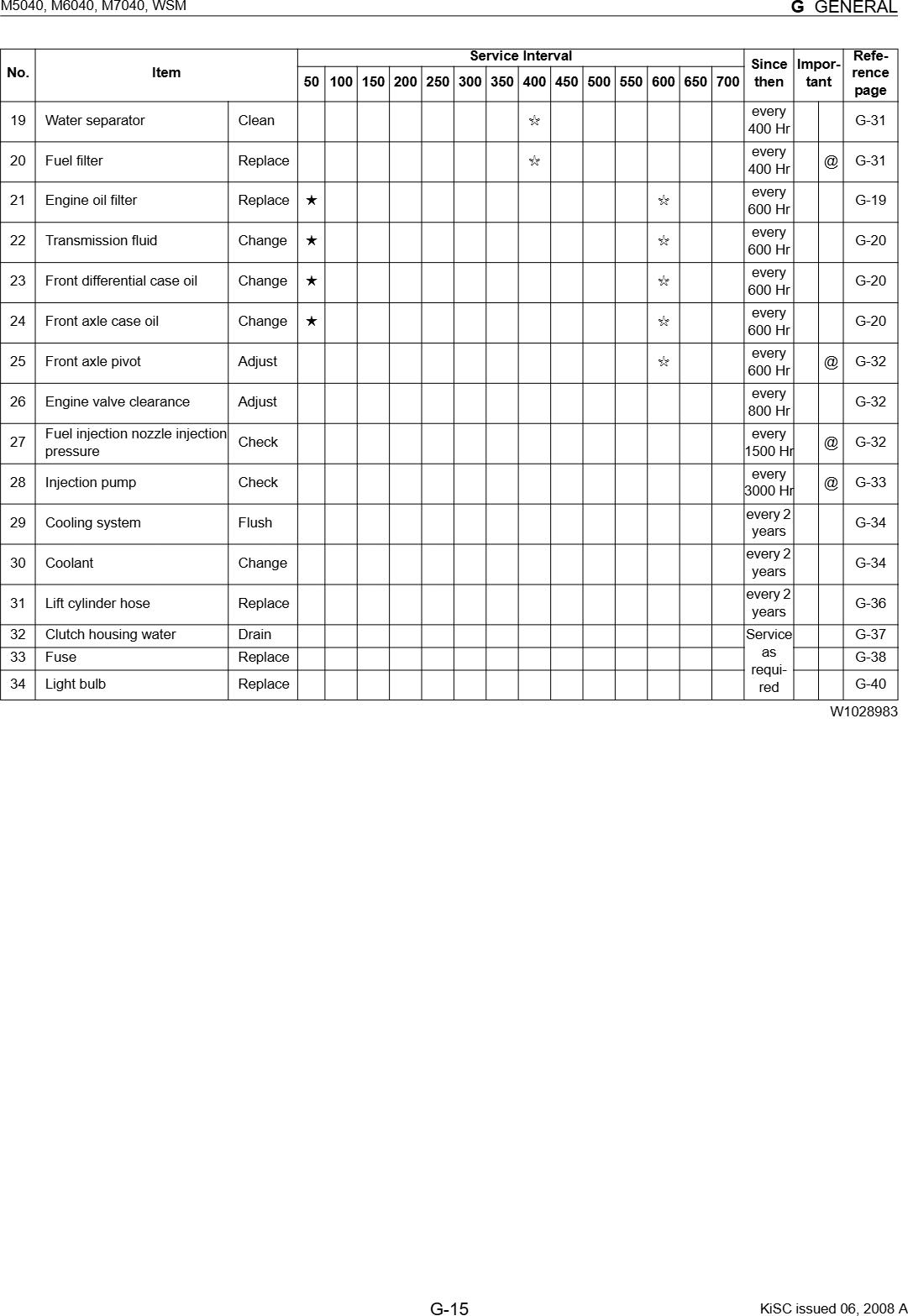
• The jobs indicated by A must be done after the first 50 hours of operafion.
• ”1: Air cleaner should be cleaned more often in dusty conditions than in normal condifions.
• ”2 : Every year or every 6 times of cleaning.
• ”3 : Replace only if necessary.
• ”4 : When Oie battery is used for less than 100 hours per year, check the battery condifion by reading Oie indicator annually.
• The items listed above (@ marked) are registered as emisson related critical parts by KUBOTA in U.S.EPA nonroad emission regulation. As the engine owner, you are responsible for Oie performance of the required maintenance on the engine according to the above insbuction. Please see the Warranty Statement in detail.
W1025390
7. CHECK AND MAINTENANCE
CAUTION
• Be sure to check and service the tractor on a flat place with engine shut off, the parking brake on and chock the wheels.
[1] DAILY CHECK
To prevent trouble from occurring, it is important to know the condition of the tractor. Check the following items before starting.
Checking
• Check areas where previous trouble was experienced.
• Walk around the tractor.
1. Check the tire pressure, and check for wear and damage.
2. Check for oil and water leak.
3. Check the engine oil level.
4. Check the transmission fluid level.
5. Check the coolant level.
6. Check the condition of ROPS attaching hardware. (ROPS model).
7. Check the washer liquid level. (CABIN model)
8. Check the water separator.
9. Check air cleaner evacuator valve.
10.Check and clean the radiator screen, grill and oil cooler.
11.Check and clean the radiator screen, grill, oil cooler and condenser (CABIN model).
12.Check and clean the air conditioner condenser screen. (CABIN model)
13.Check the nuts of tires are tight.
14.Check the number plate or SMV emblem for damage and replace as necessary if equipped.
15.Care of danger, warning and caution labels.
16.Clean around the exhaust manifold and the muffler of the engine.
• While sitting in the operator's seat.
1. Check the throttle pedal, brake pedal and clutch pedal.
2. Check the throttle lever and shuttle lever.
3. Check the parking brake.
4. Check the steering wheel.
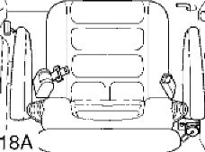
5. Check the seat belt.
• Turning the key switch.
1. Check the performance of the easy checker lights.
2. Check the head lights, turn signal lights, hazard lights and other light equipment. Clean if necessary.
3. Check the performance of the meters and gauges.
• Starting the engine.
1. Check to see that the lights on the easy checker go off.
2. Check the color of the exhaust gas.
3. Check the brakes for proper operation.
M7040 Kubota Repair Manual - DOWNLOAD
[2] CHECK POINTS OF INITIAL 50 HOURS
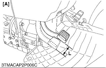
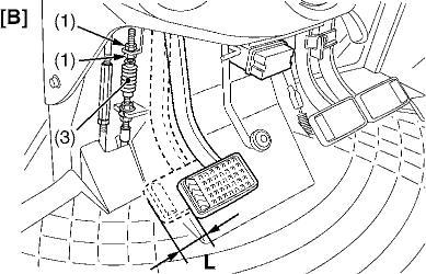
Adjusting Clutch Pedal (Synchro Shuttle Model)
1. Stop the engine and remove the key.
2. Slightly depress the clutch pedal and measure free travel at the top of pedal stroke.
3. [ROPS model]
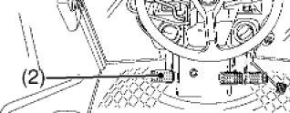
If adjustment is needed, loosen the lock nut (1) and turn the turnbuckle (2) to adjust the rod length within acceptable limits. [CABIN model]
If adjustment is needed, loosen the lock nut (1) and to adjust the cable length within acceptable limits.
• Before changing oil, be sure to stop the engine.
• Allow engine to cool down sufficiently, oil can be hot and can burn.
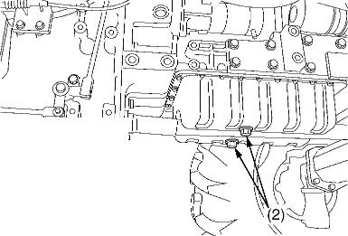
1. To drain the used oil, remove the drain plugs (2) at the bottom of the engine and drain the oil completely into the oil pan. All the used oil can be drained out easily when the engine is still warm.
2. After draining reinstall the drain plugs (2).
3. Fill with the new oil up to the upper notch on the dipstick. (Refer to “4. LUBRICANTS, FUEL AND COOLANT” in this section.)
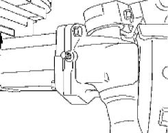
• Be sure to stop the engine before changing oil filter cartridge.
• Allow engine to cool down sufficiently, oil can be hot and can burn.
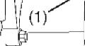
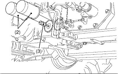
1. Remove the oil filter (1).
2. Put a film of clean engine oil on rubber seal of new filter.
3. Tighten the filter quickly until it contacts the mounting surface. Tighten filter by hand an additional 1/2 turn only.
4. After the new filter has been replaced, the engine oil normally decreases a little. Make sure that the engine oil does not leak through the seal and be sure to check the oil level on the dipstick. Then, replenish the engine oil up to the prescribed level.
■ IMPORTANT
• To prevent serious damage to the engine, use only a KUBOTA genuine filter.
(1) Engine Oil Filter
3TMACAP0P015B
W1021852
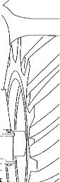
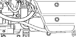
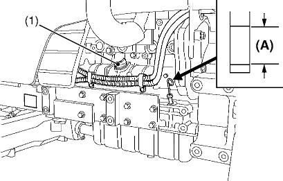
Replacing Hydraulic Oil Filter
CAUTION
• Allow engine to cool down sufficiently, oil can be hot and can burn.
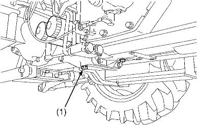
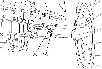
1. Remove the drain plug (1) at the bottom of the transmission case and drain the oil completely into the oil pan.
2. After draining reinstall the drain plug (1) .
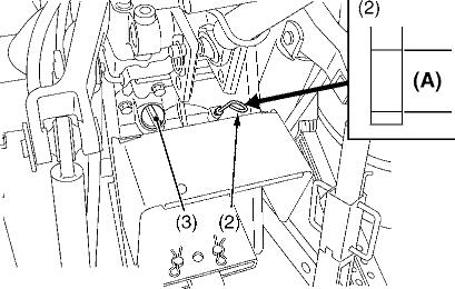
3. Remove the two oil filters (2).
4. Wipe off metal fillings with clean rags at the magnetic filters (3).
5. Put a film of clean transmission fluid on rubber seal of new filters.
6. Tighten the filter quickly until it contacts the mounting surface. Tighten filter by hand and additional 1/2 turn only.
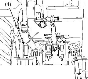
7. After the new filter has been replaced, fill with the oil up to the upper notch on the dipstick (4).
8. After running the engine for a few minutes, stop it and check the oil level again, add oil to the prescribed level.
9. Make sure that the transmission fluid doesn't leak through the seal.
■ IMPORTANT
3TMACAP0P013A
• To prevent serious damage to the hydraulic system, use only a KUBOTA genuine filter.
(1) Drain Plug (A) Oil level is acceptable within this (2) Hydraulic Oil Filter range.
(3) Magnetic Filter (Clean oPMetal Fillings)
(4) Dipstick
(S) Oil Filling Plug
W1022033
3TMACAP0P014A
3TMACAP0P015A
Changing Transmission Fluid
CAUTION
• Allow engine to cool down sufficiently, oil can be hot and can burn.
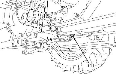
1. To drain the used oil, remove the drain plug (1) at the bottom of the transmission case and drain the oil completely into the oil pan.
2. After draining reinstall the drain plug.
3. Fill with the new KUBOTA SUPER UDT fluid up to the upper notch on the dipstick (2).
4. (Refer to “4. LUBRICANTS, FUEL AND COOLANT” in this section.)
5. After running the engine for a few minutes, stop it and check the oil level again; add oil to prescribed level.
■ IMPORTANT
• Do not operate the tractor immediately after changing the transmission fluid. Run the engine at medium speed for a few minutes to prevent damage to the transmission.
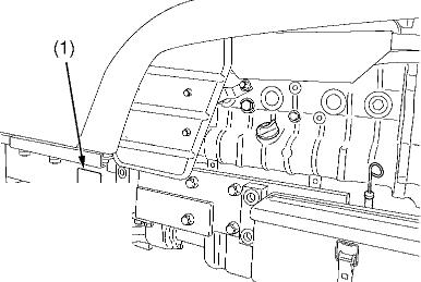
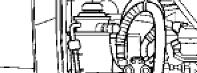
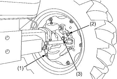
Changing Front Differential Case Oil and Front Axle Case Oil
2. After draining reinstall the drain plugs (1).
3. Remove the oil level check plugs (3).
W1022400
1. To drain the used oil, remove the drain plugs at the both front axle gear cases and filling plugs, and drain the oil completely into the oil pan.
4. Fill with the new oil up to the lower rim of check plug port on the both front axle gear cases.
5. Finally fill with the new oil up to the lower rim of check plug port on the front differential case. (Refer to “4. LUBRICANTS, FUEL AND COOLANT” in this section.)
6. After checking oil is visible through the openings of three check plugs, reinstall filling plugs and check plugs.
L Front axle gear case
(1) Drain Plug (2) Filling Port (3) Check Plug
W1063019 56 L 59.2 U.S.qts. 49.3 Imp.qts. Oil capaci
[3] CHECK POINTS OF EVERY 50 HOURS
Checking Engine Start System
CAUTION
• Do not allow anyone near the tractor while testing.
• If the tractor does not pass the test, do not operate the tractor.
■ Preparation before testing
1. Place all control levers in the “NEUTRAL” position.
2. Set the parking brake and stop the engine.
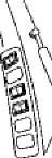
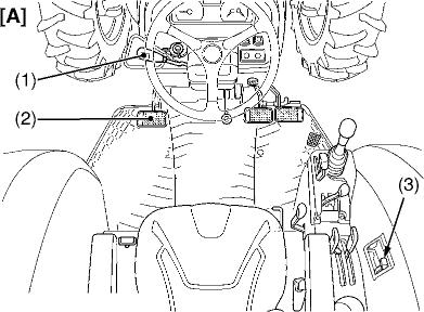
■ Test 1 : Switch for the shuttle shift lever.
1. Sit on operator's seat.
3TMACAP0P017A
2. Shift the shuttle shift lever (1) to the desired position.
3. Depress the clutch pedal (2) fully.
4. Disengage the PTO clutch control lever (3).
5. Turn the key to “START” position.
6. The engine must not crank.
7. If it cranks, inspect the safety switch.
■ Test 2 : Switch for the PTO clutch control lever.
3TMACAP0PO
WARNING
• Disconnect the implement drive universal joint from the PTO shaft, if the implement has mounted.
1. Sit on operator's seat.
2. Engage the PTO clutch control lever (3).
3. Depress the clutch pedal (2) fully.
4. Shift the shuttle shift lever (1) to the neutral position.
5. Turn the key to “START” position.
6. The engine must not crank.
7. If it cranks, inspect the safety switch.
■ Test 3 : Checking Operator Presence Control (OPC) System
WARNING
• Disconnect the implement drive universal joint from the PTO shaft, if the implement has mounted.
1. Sit on the seat.
2. Run the engine.
3. Shift the PTO lever to “ON”.
Make sure the warning buzzer does not whistle.
If the buzzer whistles while sitting on the seat, check the parts which compose the PTO safety switch.
4. Stand up from the seat.
5. The warning buzzer whistles about one second after standing up. It whistles for 10 seconds.
If the buzzer does not whistle, check the corresponding parts.
(Refer to “4. CHECKING AND ADJUSTING” at “9.
ELECTRICAL SYSTEM” section.)
(1) Shuttle Shift Lever [A] ROPS Model (2) Clutch Pedal [B] CABIN Model (3) PTO Clutch Control Lever W1062967