


SERIAL NUMBER
WB93S-5
F5APA3 andup

ATTENTION
Unsafeuseofthismachinemaycauseseriousinjury or death. Operators and maintenance personnel must read this manual before operating or maintaining this machine. This manual should be kept inside the cab for reference andperiodically reviewed by allpersonnel who will come into contact with the machine.


1.1 FOREWORD
• This manual has been produced by Komatsu Utility S.p.A. in order to supply their customers with all the necessary information on the machine and the safety regulations related to it, together with the use and maintenance instructions that enable the operator to exploit the capacity of the machine with optimal results and to keep the machine efficient over time.
• The operation manual, together with the spare parts catalogue, is an integral part of the machine and must accompany it, even when it is resold, until its final disposal.
• The manual must be handled with the greatest care and always kept on board the machine, so that it can be consulted at any moment; it must be placed in the appropriate compartment behind the seat, where also the ownership documents and the logbook are usually kept (see "3.5.9 TECHNICAL DOCUMENTATION").
• This manual must be given to the persons who have to use the machine and carry out the routine maintenance operations; they must read the contents carefully more than once, in such a way as to clearly understand what are the correct operating conditions and the dangerous conditions that must be avoided. In case of loss or damage, request a new copy to Komatsu or your Komatsu Dealer.
• The illustrations contained in this manual may represent machine configurations available on request. The machines are constantly upgraded in order to increase their efficiency and reliability; this manual sums up all the information regarding the state of the art at the moment when the machine is launched on the market. Contact your Komatsu Dealer for updated information.
• Punctual periodic annotations regarding the maintenance operations that have been carried out are important to have a clear prospect of the situation and to know exactly what has been done and what has to be done after the next maintenance interval. Therefore, it is advisable to consult both the hour meter and the maintenance plan frequently.
• Komatsu Dealers have gathered a considerable amount of experience over years of work in close contact with the users.
If more information is needed, do not hesitate to contact your Komatsu Dealer: he always knows how to get the best performance from the machine, he can recommend the equipment that is most suitable for specific needs and can provide the technical assistance necessary for any change that may be required to conform the machine to the safety standards and traffic rules.
Komatsu Dealers also provide assistance for the supply of original Komatsu spare parts, which alone guarantee safety and interchangeability.
• The table included in this manual must be filled in with the machine data, which are the data that must always be indicated to the Dealer when requiring assistance and ordering spare parB.
@ CAUTION
• The incorrect use of the machine and inappropriate maintenance operations may cause serious injury and even death.
• Operators and maintenance personnel must carefully read this manual before using the machine or performing maintenance operations.
• Some actions involved in the operation and maintenance of the machine may cause serious injury or even death, if they are not performed in compliance with the instructions given herein.
• The procedures and precautions described in this manual are valid for application to the machine only when it is used correctly. If the machine is used for any purpose or in any way other than those described herein, the operator shall be responsible for his own safety and for the safety of any other person involved.
1.2 INFORMATION ON SAFETY
Many accidents are caused by insufficient knowledge of and failure to comply with the safety regulations prescribed for the maintenance operations that must be performed on the machine.
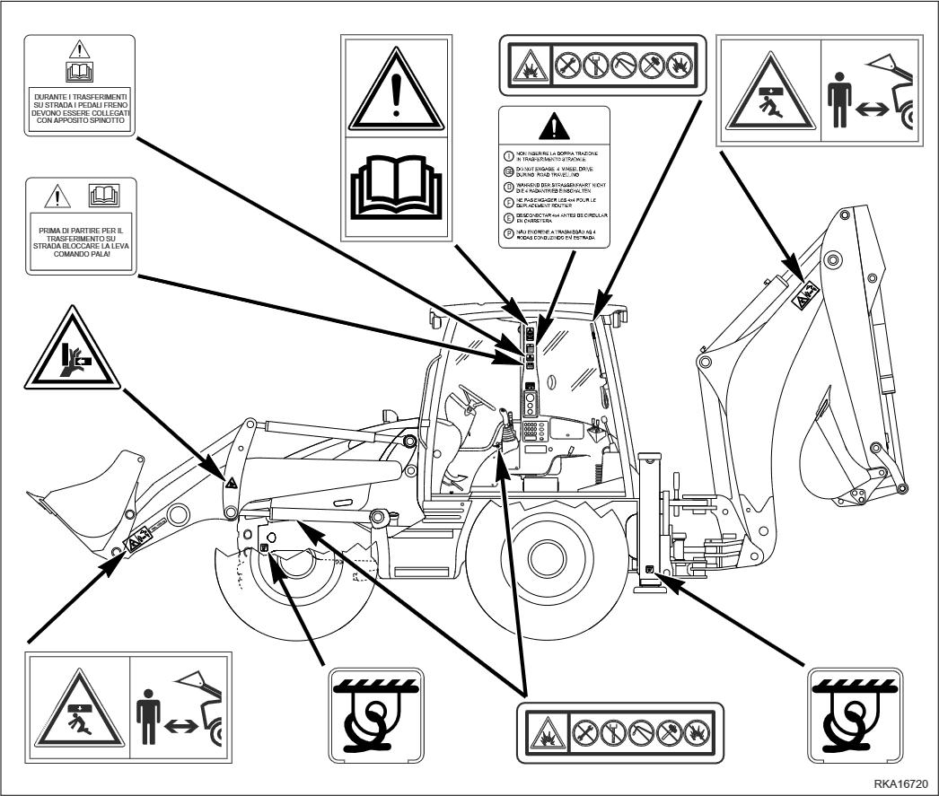
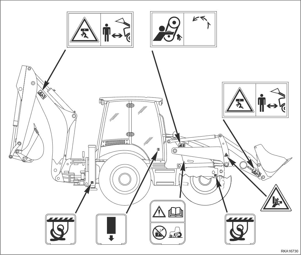
In order to avoid accidents, before starting work and before carrying out any maintenance operation, carefully read and be sure to understand all the information and warnings contained in this manual and given on the plates applied onto the machine. To allow the operator to use the machine in total safety, precautions and safety plates are described in this manual and applied to the machine in order to supply information regarding situations that involve potential risks and the measures that may be adopted to avoid such situations.
Terminology used in the signs
The following terms are used in the signs to inform the user that there is a situation of potential danger that may cause injury or damage.
In this manual and in the plates applied to the machine the following terms are used to indicate potential dangers.
@ DANGER
• Indicates a situation of imminent danger that, if not avoided, may cause serious injury and even death. The use of this term must be limited to situations of extreme danger.
@ WARNING
• Indicates a situation of potential danger that, if not avoided, may cause serious injury and even death.
CAUTION
• Indicates a situation of potential danger that, if not avoided, may cause moderate injury. This term can also be used as a warning in case of dangerous procedures.
Other terms used in the signs
In addition to those indicated above, the following warning terms are used to recommend the precautions to be taken to protect the machine or to supply useful information.
IMPORTANT
• This term is used to indicate precautions that must be taken in order to avoid actions that may reduce the life of the machine.
NOTE
• This word is used to indicate a useful piece of information.
Komatsu cannot reasonably predict every circumstance that might involve a potential hazard during the operation or maintenance of the machine; for this reason, the safety messages included in this manual and applied onto the machine may not include all possible safety precautions. If all the procedures and operations prescribed for this machine are kept to, you can be sure that the operator and the persons in the vicinity will work in total safety, with no risk of damaging the machine. In case of doubt regarding the safety measures necessary for some procedures, contact Komatsu or your local Dealer.
@ DANGER
• Before starting any maintenance operation, position the machine on firm and level ground, engage the safety locks of the equipment and of the controls, stop the engine and apply the parking brake.
• To make the information clearer, some illustrations in this manual represent the machine without safety guards. Do not use the machine without guards and do not start the engine when the hood is open, unless this is expressly prescribed for certain maintenance operations.
• It is strictly forbidden to modify the setting of the hydraulic system safety valves; Komatsu cannot be held liable for any personal injury, or damage to property or the machine, if this has been tampered with by modifying the standard setting of the hydraulic system.
• Before carrying out any electric welding operation, disconnect the battery and the alternator. (See "2.8.13 PRECAUTIONS TO BE TAKEN WHEN HANDLING THE BATTERY AND THE ALTERNATOR").
• Install only authorized additional equipment (See "6.1 AUTHORIZED OPTIONAL EQUIPMENT').
• The machine can travel on roads only if equipped with suitable lighting, signalling and safety devices and if this type of use is authorized by the logbook. Before travelling on roads, make sure that the equipment with which the machine is provided is homologated and that the safety locks are correctly engaged.
DANGER
• It is absolutely forbidden to manoeuvre the machine while standing on the ground. Each operation must be carried out by the operator correctly seated in the driving position.
1.3 INTRODUCTION
1.3.1 INTENDED USES
The Komatsu BACKHOE LOADERS described in this manual have been designed and constructed to be used mainly with the following functions:
• LOADER
• EXCAVATOR
Through the installation of optional equipment, the machine can also be used for the following applications:
• HANDLING OF MATERIALS (4IN1 BUCKET - PALLET FORKS)
• SNOWPLOUGH (ANGLEDOZER BLADE - SNOWPLOUGH)
• DEMOLITION (HAND HAMMER - HAMMER ON THE BACKHOE)
• DITCH CLEANING AND DIGGING (SPECIAL BUCKETS)
1.3.2 IMPROPER OR UNAUTHORIZED USE
@ CAUTION
• This paragraph describes some improper or unauthorized uses of the machine; since it is impossible to predict all possible improper uses, if the machine is going to be used for particular applications, contact your Komatsu Dealer before carrying out the work.
IMPORTANT
• The instructions regarding the authorized optional equipment are given in the relevant operation and maintenance manuals; if the equipment is supplied by Komatsu, these publications are enclosed to this manual.
• The instructions regarding the assembly of the authorized equipment, the controls requiring special arrangements on the machine and the hydraulic couplings necessary for the operation of the equipment are grouped in the final section of this manual.
Komatsu BACKHOE LOADERS are constructed exclusively for the handling, excavation and treatment of inert materials; therefore, the following uses are absolutely forbidden:
• USE OF THE MACHINE BY MINORS OR INEXPERIENCED PERSONS.
• USE OF THE MACHINE FOR LIFTING PERSONS OR OBJECTS.
• TRANSPORTATION OF PERSONS even if they are in the operator's cab.
• TRANSPORTATION OF CONTAINERS with fluids, flammable fluids, loose material, without the appropriate slinging equipment.
• TRANSPORTATION AND LIFTING (EVEN IF IN EXCEPTIONAL CASES) OF EQUIPMENT OR MATERIALS THAT PROTRUDE FROM THE BUCKET OR ARE NOT SECURED TO THE BUCKET BY MEANS OF ROPES OR CHAINS.
• USE OF THE BUCKET FOR DRIVING OR EXTRACTING PILES.
• USE OF THE MACHINE FOR TOWING DAMAGED VEHICLES ON ROADS.
• USE OF THE MACHINE FOR LIFTING DAMAGED VEHICLES.
1.3.3 MAIN CHARACTERISTICS
• Simple and easy operation.
• Servo-assisted steering with priority hydraulic system.
• Three steering modes selected by means of microswitches in pairs.
- Two-wheel steering (2WS)
- Four-wheel steering (4WS ROUND)
- Four-wheel steering (4WS CRAB)
• 4-gear mechanical gearshift and transmission with hydraulic converter; reversal controlled by a lever positioned under the steering wheel.
• Loader control through a single servo lever ensuring also combined movements that can be modulated proportionally and continually.
• Backhoe controls through mechanical levers ensuring also combined movements that can be modulated proportionally and continually. On request, the backhoe can be controlled by means of two servo levers.
• Complete series of instruments visible from the two operating positions (loader or backhoe).
• Separate accelerator controls for the two operating positions.
• Foot brake control.
• Easy maintenance with simplified intervals.
• Automatic engagement and disengagement of the differential locking on both axles (front and rear).
1.3.4 RUNNING-IN
Every machine is scrupulously adjusted and tested before delivery.
A new machine, however, must be used carefully for the first 100 hours, in order to ensure proper running-in of the various components.
If the machine is subjected to an excessive work load at the beginning of its service life, its productivity and functionality will be untimely reduced.
Every new machine must be used carefully, paying special attention to the following indications:
• After the start, let the engine idle for 5 minutes, in such a way as to warm it up gradually before actual operation.
• Avoid operating the machine with the limit loads allowed or at high speed.
• Avoid abrupt starts or accelerations, useless sudden decelerations and abrupt reversals.
• After the first 250 hours of use, carry out the following operations, in addition to those to be performed every 250 hours:
1 - Change the hydraulic transmission oil and filter.
2 - Change the differential unit oil (front and rear axle).
3 - Change the final reduction gear oil (front and rear axle).
4 - Change the hydraulic circuit oil filter.
SYNTHETIC BIODEGRADABLE OIL TYPE HEES
On machines in which the synthetic biodegradable oil type HEES is used, the following operations are to be performed together with the standard maintenance operations.
• After the first 50 hours of operation, change the hydraulic circuit drain filter.
• After the first 500 hours of operation, change the hydraulic circuit oil.
IMPORTANT
• When changing the oil filters (cartridges), check their innner part to make sure that there are no deposits.
If abundant deposits are observed, find out what may have caused their accumulation before starting the machine.
• The number of operation hours is indicated by the hour meter.
1.4 PRODUCT IDENTIFICATION
The Komatsu backhoe loader and its main components are identified by serial numbers stamped on the identification plates. The serial number and the identification numbers of the components are the only numbers that must be indicated to the Dealer when requiring assistance and ordering spare parts.
1.4.1 MACHINE IDENTIFICATION NUMBER (PIN)
The machine identification number "PIN" is stamped on the right side of the frame front.

1.4.2 MACHINE IDENTIFICATION PLATE AND PRODUCT IDENTIFICATION NUMBER (PIN) (alternatively for some markets)
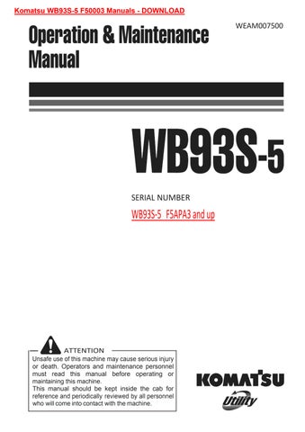
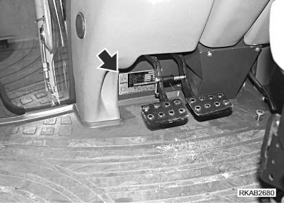
The Komatsu BACKHOE LOADERS described in this manual are CE marked, in fact they are in full compliance with the EU harmonised standards. The Product Identification Number (PIN) is stamped on the lower part of the plate. The customer must be able to indicate the PIN at any time, that is why it must compulsorily be written in the following table. The plate with the CE marking is applied inside the cab, on the left vertical wall of the frame, at the height of the brake pedals.


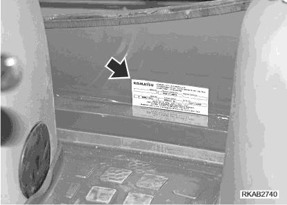
1.4.3 MACHINE IDENTIFICATION PLATE AND PRODUCT IDENTIFICATION NUMBER (PIN)
The Komatsu BACKHOE LOADERS described in this manual are CE marked, in fact they are in full compliance with the EU harmonised standards.
The Product Identification Number (PIN) is stamped on the lower part of the plate. The customer must be able to indicate the PIN at any time, that is why it must compulsorily be written in the following table. The plate with the CE marking is applied inside the cab, on the left vertical wall of the frame, at the height of the brake pedals.
1.4.4
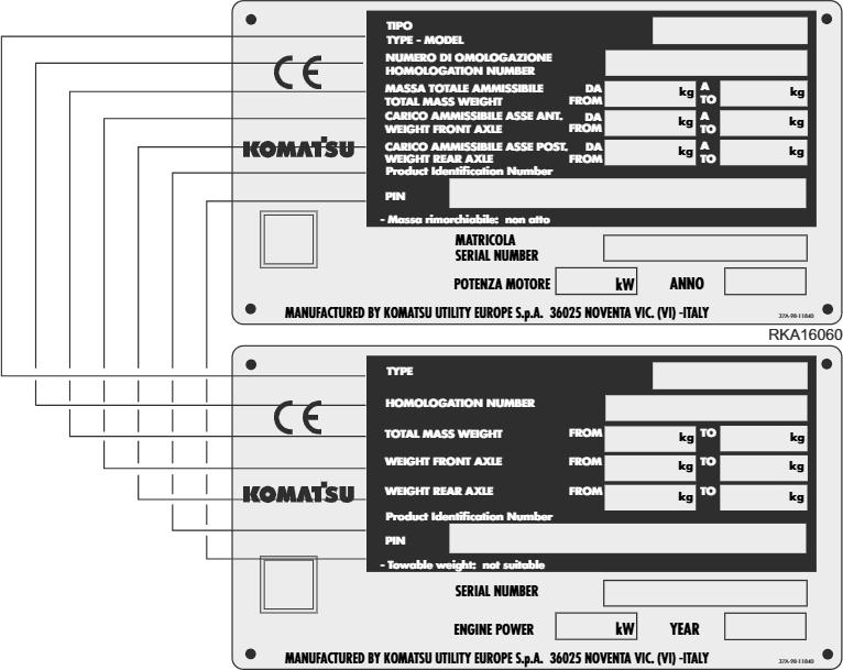
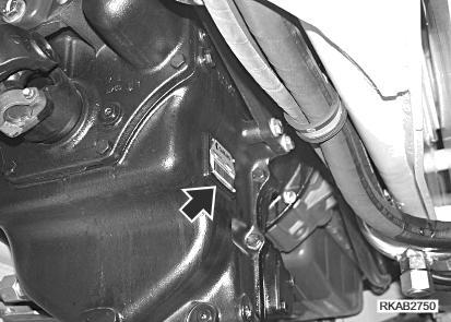
ENGINE SERIAL NUMBER AND EXHAUST GAS EMISSION PLATE
The identification plate (1) is fixed above the engine head and indicates the engine model, total displacement and serial number.
The identification plate (2) is fixed to the left side of the engine block, bears the Manufacturer's mark and contains the following data:
1 - Engine type
2 - Engine family
3 - Serial number
4 - EC Type Approval
5 - EPA
The serial number (3) is also stamped on the right side of the cylinder block, on the upper part of the oil cooling heat exchanger.


1.4.5 FRONT AXLE SERIAL NUMBER
The serial number of the rear axle is stamped on the plate positioned on the right side of the axle body.

1.4.6 REAR AXLE SERIAL NUMBER
The serial number is stamped on the plate positioned on the left side of the axle body.

1.4.7 TRANSMISSION SERIAL NUMBER
The transmission serial number is stamped on the plate postioned on the right side of the transmission case.
1.4.8 CAB SERIAL NUMBER
The cab serial number is stamped on the plate postioned on the left side of the rear wall.
1.4.9
SERIAL NUMBERS AND DEALER'S ADDRESS
Machine no.
Product identification number (PIN)
Engine no.
Front axle no.
Rear axle no.
Transmission no.
Cab no.
Dealer:
Mod.
Address: Tel.
Contact person:
NOTES:
3.3.3
MAINTENANCE
4.1 GUIDE TO MAINTENANCE 4.2 MAINTENANCE NOTES
4.2.1 NOTES REGARDING THE ENGINE
4.2.1.1 ENGINE OIL............................................................................................................
4.2.1.2 COOLANT...............................................................................................................
4.2.1.3 FUEL
4.2.2 NOTES REGARDING THE HYDRAULIC SYSTEM.................................................................
4.2.3 NOTES REGARDING THE ELECTRIC SYSTEM....................................................................
4.2.4 NOTES REGARDING LUBRICATION
4.2.5 PARTS SUBJECT TO WEAR THAT PERIODICALLY NEED CHANGING..............................
4.5 FUEL, COOLANT AND LUBRICANTS.................................................................................................
4.3.1 LUBRICATION WITH GREASE
4.3.2 HOMOLOGATED SYNTHETIC BIODEGRADABLE LUBRICANTS “HEES”
DRIVING TORQUES
4.4.1 STANDARD DRIVING TORQUES FOR SCREWS AND NUTS
4.4.2 SPECIFIC DRIVING TORQUES FOR SCREWS AND NUTS .................................................
4.4.3 STANDARD DRIVING TORQUES FOR HOSES WITH ORFS................................................
LUBRICATION ......................................................................................................................................
4.5.1 LUBRICATION DIAGRAM........................................................................................................
4.5.2 LUBRICATION DIAGRAM (4in1 bucket and pallet forks)
4.5.3 LUBRICATION DIAGRAM (front bucket quick couplings)........................................................
4.5.4 LUBRICATION DIAGRAM (offset device)
4.6 PERIODICAL CHANGE
4.6.1
4.6.1.1 FUEL SYSTEM .......................................................................................................
4.6.1.2 DELIVERY HYDRAULIC SYSTEM
4.6.1.3 FRONT LOADER HYDRAULIC SYSTEM...............................................................
4.6.1.4 BACKHOE HYDRALIC SYSTEM............................................................................
4.6.1.5 OPERATOR'S SAFETY..........................................................................................
4.8.1.a CHECKING, CLEANING OR CHANGING THE ENGINE AIR FILTERS
4.8.1.b CHECKING AND CLEANING THE CAB AIR FILTER
4.8.1.c CHECKING AND CLEANING THE AIR RECIRCULATION FILTER (only for machines with air conditioner)...................................................................
4.8.1.d CHECKING THE DETERGENT LEVEL IN
4.8.1.e
4.8.1.f
4.8.1.g
4.8.1.h CHECKING THE WINDSHIELD WIPER BLADES.................................................. LUBRICATING THE CAB DOOR HINGES FUSES AND RELAYS CHECK AND CHANGE BLEEDING THE BRAKING CIRCUIT
4.8.1.i CHECKING AND ADJUSTING THE WHEEL TOE-IN
4.8.1.j CHECKING THE BRAKING EFFICIENCY..............................................................
4.8.1.k CHECKING AND ADJUSTING THE PARKING BRAKE
4.8.1.1 CHECKING AND ADJUSTING THE BRAKE PEDAL STROKE
4.8.1.m ADJUSTING THE AUTOMATIC RETURN-TO-DIG DEVICE OF THE FRONT BUCKET (if installed) ..............................................................................................
4.8.1.n CHECKING AND ADJUSTING THE STABILIZER SLACK.....................................
4.8.2 MAINTENANCE INTERVALS IN CASE OF USE OF THE DEMOLITION HAMMER
4.8.2.a CHANGING THE HYDRAULIC OIL FILTER...........................................................
4.8.2.b
4.8.3 CHECKS TO BE CARRIED OUT BEFORE STARTING THE ENGINE
4.8.3.a VARIOUS CHECKS
4.8.3.b CHECKING THE COOLANT LEVEL.......................................................................
4.8.3.c CHECKING THE FUEL LEVEL
4.8.3.d CHECKING THE ENGINE OIL LEVEL
4.8.4 MAINTENANCE EVERY 10 HOURS OF OPERATION
4.8.4.a LUBRICATING THE JOINTS
4.8.5 MAINTENANCE AFTER THE FIRST 50 HOURS OF OPERATION (Only for machines in which synthetic biodegradable oil type HEES is used)..........................
4.8.6 MAINTENANCE EVERY 50 HOURS OF OPERATION
4.8.6.a CHECKING THE HYDRAULIC OIL LEVEL ............................................................
4.8.6.b CHECKING THE FLUID LEVEL IN THE RADIATOR
4.8.6.c CHECKING THE BRAKING SYSTEM
4.8.6.d LUBRICATING THE PROPELLER SHAFTS
4.8.6.e LUBRICATING THE FRONT AXLE JOINTS AND CENTRAL COUPLING AND THE REAR AXLE
4.8.9
CHECKING AND ADJUSTING THE A/C COMPRESSOR
4.8.13 MAINTENANCE EVERY 3000 HOURS OF OPERATION
4.8.13.a CHECKING THE ENGINE RETAINING SCREWS AND DAMPING ELEMENTS
4.8.13.b CHECKING AND ADJUSTING THE ENGINE VALVE CLEARANCE AND THE INJECTION TIMING ADVANCE.............................................................
4.8.14 MAINTENANCE EVERY 4000 HOURS OF OPERATION
4.8.14.a CHANGING THE A/C DEWATERING FILTER (Only for machines with air conditioner)
4.8.14.b CHECKING THE OPERATING CONDITIONS OF THE A/C COMPRESSOR (Only for machines with air conditioner)
4.8.14.c CHANGING THE ENGINE THERMOSTATIC VALVE
SPECIFICATIONS
AUTHORIZED OPTIONAL EQUIPMENT
6.1 AUTHORIZED OPTIONAL EQUIPMENT
6.1.1 PRECAUTIONS REGARDING SAFETY..................................................................................
6.1.2 PRECAUTIONS REGARDING THE INSTALLATION OF EQUIPMENT..................................
6.1.3 CHARACTERISTICS OF THE OPTIONAL EQUIPMENT........................................................
6.2 FRONT EQUIPMENT QUICK COUPLING DEVICES...........................................................................
6.2.1 MANUAL QUICK COUPLING ..................................................................................................
6.2.2 HYDRAULIC QUICK COUPLING FOR STANDARD BUCKET
6.2.3 HYDRAULIC QUICK COUPLING FOR 4in1 BUCKET AND OPTIONAL EQUIPMENT WITH UNIDIRECTIONAL OIL FLOW
6.3 4in1 BUCKET.......................................................................................................................
6.3.1 DESCRIPTION AND CONTROLS
6.3.2 SAFETY DEVICES
6.3.3 INSTALLING THE 4in1 BUCKET
6.3.4 USING THE 4in1 BUCKET
6.3.5 MAINTENANCE
6.4 PALLET FORKS ...................................................................................................................................
6.4.1 DESCRIPTION
6.4.2 SAFETY DEVICES
6.4.3 USING THE FORKS
6.4.3.1 PREPARING THE PALLET FORKS FOR USE
6.4.3.2 OVERTURNING THE FORKS
6.4.4 REMOVING THE FORKS
6.4.5 INSTALLING THE FORKS .......................................................................................................
6.4.6 MAINTENANCE
6.5 BACKHOE TELESCOPIC ARM............................................................................................................
6.5.1 DESCRIPTION AND CONTROL..............................................................................................
6.5.1.1 CONTROL (version with mechanically-controlled backhoe)
6.5.1.2 CONTROL (version with servo-assisted backhoe)..................................................
6.5.2 SAFETY DEVICES
6.5.3 USING THE TELESCOPIC ARM .............................................................................................
6.5.4 MAINTENANCE..................................................................................................................
6.5.4.1 ADJUSTING THE GUIDE SLACK...........................................................................
6.6 CONFIGURATION FOR THE INSTALLATION OF THE DEMOLITION HAMMER..............................
6.6.1 DESCRIPTION AND CONTROL..............................................................................................
6.6.1.1 CONTROL (version with mechanically-controlled backhoe)
6.6.1.2 CONTROL (version with servo-assisted backhoe)..................................................
6.6.2 USE OF THE DEMOLITION HAMMER AND RULES TO BE OBSERVED
6.6.3 INSTALLING AND REMOVING THE DEMOLITION HAMMER...............................................
6.6.3.1 INSTALLING THE HAMMER
6.6.3.2 REMOVING THE HAMMER....................................................................................
6.6.4 USING THE HAMMER
6.6.5
6.7 APPLICATION OF THE OFFSET DEVICE...........................................................................................
6.7.1 DESCRIPTION AND CONTROL..............................................................................................
6.7.1.1 CONTROL (version with mechanically-controlled backhoe)
6.7.1.2 CONTROL (version with servo-assisted backhoe)..................................................
6.8 CONFIGURATION FOR THE USE OF OPTIONAL EQUIPMENT WITH UNIDIRECTIONAL OIL FLOW
6.8.1 DESCRIPTION AND CONTROL..............................................................................................
6.8.1.1 CONTROL (version with mechanically-controlled backhoe)
6.8.1.2 CONTROL (version with servo-assisted backhoe)..................................................
6.8.2 INSTALLING AND CONNECTING THE EQUIPMENT
6.8.3 MAINTENANCE..................................................................................................................
6.9 CONFIGURATION FOR THE USE OF THE CLAMSHELL BUCKET
6.9.1 DESCRIPTION AND CONTROL..............................................................................................
6.9.1.1 CONTROL (version with mechanically-controlled backhoe)
6.9.1.2 CONTROL (version with servo-assisted backhoe)..................................................
6.9.2 INSTALLING THE CLAMSHELL BUCKET...............................................................................
6.9.3 USING THE CLAMSHELL BUCKET
6.9.4 MAINTENANCE..................................................................................................................
6.10 CONFIGURATION FOR THE USE OF THE HAND HYDRAULIC HAMMER.......................................
6.10.1 DESCRIPTION AND CONTROL..............................................................................................
6.10.2 INSTALLING AND REMOVING THE HAND HAMMER
6.10.2.1 CONNECTING THE HAND HAMMER....................................................................
6.10.2.2 REMOVING THE CONNECTIONS . .... ....
6.10.3 USING THE HAMMER
6.10.4
6.12 REAR EQUIPMENT MECHANICAL QUICK COUPLING DEVICE
6.12.1 EQUIPMENT COUPLING AND RELEASE PROCEDURE
6.12.2