00 Index and foreword Index
00-10 PC138USLC-10 Removal and installation of main pump assembly 50-133 Removal and installation of control valve assembly 50-137 Disassembly and assembly of control valve assembly 50-143 Disassembly and assembly of work equipment PPC valve assembly 50-145 Disassembly and assembly of travel PPC valve assembly.............................................................. 50-147 Work equipment ...........................................................................................................................................50-149 Removal and installation of work equipment assembly 50-149 Disassembly and assembly of work equipment cylinder assembly 50-153 Cab and its attachments 50-158 Removal and installation of operator's cab assembly....................................................................... 50-158 Removal and installation of operator's cab door ............................................................................... 50-161 Removal and installation of operator's cab glass (adhered glass) 50-164 Removal and installation of front window assembly 50-175 Removal and installation of floor frame assembly 50-176 Removal and installation of air conditioner unit assembly................................................................ 50-183 Removal and installation of air conditioner compressor assembly 50-187 Removal and installation of air conditioner condenser assembly 50-189 Removal and installation of operator's seat 50-191 Removal and installation of seat belt 50-192 Removal and installation of front wiper assembly.............................................................................. 50-193 Electrical system 50-199 Removal and installation of engine controller assembly 50-199 Removal and installation of pump controller assembly 50-200 Removal and installation of machine monitor assembly 50-202 Removal and installation of mass air flow and temperature sensor.................................................50-204 Removal and installation of KOMTRAX terminal assembly 50-205 60 Maintenance standard 60-1 Table of contents 60-2 Engine and cooling system 60-3 Engine mount............................................................................................................................................ 60-3 PTO 60-4 Cooling system 60-5 Power train 60-6 Swing circle 60-6 Swing machinery...................................................................................................................................... 60-7 Sprocket. 60-8 Undercarriage and frame 60-9 Track frame 60-9 Idler cushion............................................................................................................................................60-10 Idler.......................................................................................................................................................... 60-11 Track roller 60-12 Carrier roller 60-13 Track shoe 60-14 Hydraulic system 60-19 Hydraulic tank.........................................................................................................................................60-19 Main pump 60-20 Control valve 60-23 Swing motor 60-34 Travel motor............................................................................................................................................60-37 Work equipment and swing PPC valve 60-38 Travel PPC valve 60-41 Blade PPC valve 60-44 1st-line attachment PPC valve (with EPC valve) 60-46 Solenoid valve 60-49 Attachment circuit selector valve (for low pressure circuit)..................................................................60-51 Attachment circuit selector valve (for high pressure circuit) 60-52 Center swivel joint 60-53 Cab and its attachments 60-54 Cab mount and cab tipping stopper 60-54
00 Index and foreword Index PC138USLC-10 00-11 Work equipment 60-55 Work equipment 60-55 Boom cylinder 60-64 Arm cylinder 60-65 Bucket cylinder .......................................................................................................................................60-66 Blade cylinder .........................................................................................................................................60-67 80 Appendix 80-1 Table of contents 80-2 Air conditioner components 80-3 Precautions for refrigerant........................................................................................................................ 80-3 Air conditioner component........................................................................................................................ 80-4 Configuration and function of refrigeration cycle 80-7 Outline of refrigeration cycle 80-8 Air conditioner unit 80-10 Dual pressure switch.............................................................................................................................. 80-15 Air conditioner controller 80-16 Compressor 80-17 Air conditioner condenser 80-18 Sunlight sensor 80-20 Outer temperature sensor (outside air temperature sensor)...............................................................80-21 Procedure for testing and troubleshooting 80-22 Circuit diagram and arrangement of connector pins 80-24 System diagram 80-26 Input and output signals of the air conditioner controller 80-27 Air conditioner unit..................................................................................................................................80-29 Parts and connectors layout 80-31 Testing air leakage (duct) 80-37 Testing with self-diagnosis function 80-40 Testing vent (mode) changeover 80-43 Testing FRESH/RECIRC air changeover.............................................................................................. 80-44 Testing sunlight sensor 80-45 Testing (dual) pressure switch for refrigerant 80-46 Testing relays 80-48 Troubleshooting chart 1 80-49 Troubleshooting chart 2......................................................................................................................... 80-50 Information in troubleshooting table 80-53 Failure code list related to air conditioner 80-54 Failure code [879AKA] A/C Inner Sensor Open Circuit 80-55 Failure code [879AKB] A/C Inner Sensor Short Circuit........................................................................80-56 Failure code [879BKA] A/C Outer Sensor Open Circuit ......................................................................80-57 Failure code [879BKB] A/C Outer Sensor Short Circuit 80-59 Failure code [879CKA] Ventilating Sensor Open Circuit 80-61 Failure code [879CKB] Ventilating Sensor Short Circuit 80-62 Failure code [879DKZ] Sunlight Sensor Open or Short Circuit 80-63 Failure code [879EMC] Ventilation Damper Abnormality.....................................................................80-65 Failure code [879FMC] Air Mix Damper Abnormality 80-66 Failure code [879GKX] Refrigerant Abnormality 80-67 A-1 Troubleshooting for power supply system (Air conditioner does not operate) 80-68 A-2 Troubleshooting for compressor and refrigerant system (Air is not cooled)...............................80-70 A-3 Troubleshooting for blower motor system (No air comes out or air flow is abnormal) 80-73 A-4 Troubleshooting for FRESH/RECIRC air changeover 80-75 Troubleshooting with gauge pressure. 80-77 Connection of service tool 80-80 Precautions for disconnecting and connecting refrigerant piping.......................................................80-82 Handling of compressor oil 80-84 Desiccant replacement 80-86 90 Diagrams and drawings 90-1 Table of contents 90-2
00-12 PC138USLC-10 Hydraulic circuit diagram 90-3 Symbols in hydraulic circuit diagram 90-3 Hydraulic circuit diagram 90-7 Electric circuit diagram 90-9 Symbols in electric circuit diagram...........................................................................................................90-9 Electrical circuit diagram .........................................................................................................................90-13 Electrical circuit diagram of air conditioner unit 90-25 Index 1
00 Index and foreword Index
Foreword, safety and general information (ALL-0370-001-A-00-A)
Important safety notice (ALL-1120-012-A-01-A)
(Rev. 2012/10)
• Appropriate servicing and repair are extremely important to ensure safe operation of the machine. The shop manual describes the effective and safe servicing and repair methods recommended by Komatsu. Some of these methods require the use of the special tools designed by Komatsu for the specific purpose.
• The symbol mark k is used for such matters that require special cautions during the work. The work indicated by the caution mark should be performed according to the instructions with special attention to the cautions. Should hazardous situation occur or be anticipated during such work, be sure to keep safe first and take every necessary measure.
General precautions
k Inappropriate handling causes an extreme danger. Read and understand what is described in the operation and maintenance manual before operating the machine. Read and understand what is described in this manual before starting the work.
• Before performing any greasing or repairs, read all the safety labels stuck to the machine. For the locations of the safety labels and detailed explanation of precautions, see the operation and maintenance manual.
• Locate a place in the repair workshop to keep the tools and removed parts. Always keep the tools and parts in their correct places. Always keep the work area clean and make sure that there is no dirt, water or oil on the floor. Smoke only in the areas provided for smoking. Never smoke while working.
• When performing any work, always wear the safety shoes and helmet. Do not wear loose work cloths, or clothes with buttons missing.
1. Always wear the protective eyeglasses when hitting parts with a hammer.
2. Always wear the protective eyeglasses when grinding parts with a grinder, etc.
• When performing any work with two or more workers, always agree on the working procedure before starting. While working, always keep conversations of the work between your fellow workers and your self on any step of the work. During the work, hang the warning tag of "UNDER WORKING" in the operator's compartment.
• Only qualified workers must perform the work and operation which require license or qualification.
• Keep the tools in good condition. And learn the correct way to use the tools, and use the proper ones among them. Before starting the work, thoroughly check the tools, lift truck, service vehicle, etc.
• If welding repairs is required, always have a trained and experienced welder with good
knowledge of welding perform the work. When performing welding work, always wear welding gloves, apron, shielding goggles, cap, etc.
• Before starting work, warm up your body thoroughly to start work under good condition.
• Avoid continuing work for long hours and take rests with proper intervals to keep your body in good condition. Take a rest in a specified safe place.
Safety points
1 Good arrangement
2 Correct work clothes
3 Observance of work standard
4 Practice of making and checking signals
5 Prohibition of operation and handling by unlicensed workers
6 Safety check before starting work
7 Wearing protective goggles (for cleaning or grinding work)
8 Wearing shielding goggles and protectors (for welding work)
9 Good physical condition and preparation
10 Precautions against work which you are not used to or you are used to too much
Preparation
• Before adding oil or making any repairs, place the machine on a firm and level ground, and apply the parking brake and chock the wheels or tracks to prevent the machine from moving.
• Before starting work, lower the work equipment (blade, ripper, bucket, etc.) to the ground. If it is not possible to lower the equipment to the ground, insert the lock pin or use blocks to prevent the work equipment from falling. And be sure to lock all the work equipment control levers and hang a warning tag on them.
• When performing the disassembling or assembling work, support the machine securely with blocks, jacks, or stands before starting the work.
• Remove all of mud and oil from the steps or other places used to get on and off the machine completely. Always use the handrails, ladders of
00 Index and foreword Foreword, safety and general information PC138USLC-10 00-13
steps when getting on or off the machine. Never jump on or off the machine. When the scaffold is not provided, use steps or stepladder to secure your footing.
Precautions during work
• For the machine equipped with the battery disconnect switch, check that the system operating lamp is turned off before starting the work. Then, turn the battery disconnect switch to OFF (Q) position and remove the switch key. For the machine not equipped with the battery disconnect switch, remove the cable from the battery before starting the work. Be sure to remove the negative end (-) of the battery cable first.
• Release the remaining pressure in the circuits completely before the work when the parts in the circuits of oil, fuel, coolant and air are disconnected or removed. When the cap of the oil filter, drain plug or oil pressure pickup plug is removed, loose them slowly to prevent the oil from spurting out.
• When removing or installing the checking plug or the piping in the fuel circuit, wait 30 seconds or longer after the engine is shut down and start the work after the remaining pressure is released from the fuel circuit.
• Immediately after the engine is shut down, the coolant and oil in the circuits are hot. Be careful not to get scalded by the hot coolant and oil. Start the work after checking that the coolant and oil are cooled down sufficiently.
• Start the work after the engine is shut down. Be sure to shut down the engine when working on or around the rotating parts in particular. When checking the machine without shutting down the engine (measuring oil pressure, rotational speed, oil or coolant temperature), take extreme care not to get caught in the rotating parts or the working equipment.
• The hoist or crane must be used to sling the components weighing 25 kg or heavier. Check the slings (wire rope, nylon sling, chain and hook) for damage before the work. Use the slings with ample capacity and install them to the proper places. Operate the hoist or crane slowly to prevent the component from hitting any other part. Do not work with any part still raised by the hoist or crane.
• When removing the part which is under internal pressure or reaction force of the spring, always leave 2 bolts in diagonal positions. Loosen those 2 bolts gradually and alternately and release the pressure, then, remove the part.
• When removing the part, be careful not to break or damage the electrical wiring. The damaged wiring may cause electrical fires.
• When removing piping, prevent the fuel or oil from spilling out. If any fuel or oil drips onto the floor, wipe it off immediately. Fuel or oil on the floor can cause you to slip and can even cause fires.
• As a general rule, do not use gasoline to wash parts. Do not use gasoline to clean the electrical parts, in particular.
• Reinstall the parts removed to their original places. Replace the damaged parts and the parts which must not be used with new ones. When installing the hoses and wiring harnesses, be careful that they are not damaged by contacting with other parts when the machine is operated.
• When connecting the high pressure hoses and tubes, make sure that they are not twisted. The damaged high pressure hoses and tubes are very dangerous when they are installed. So, be extremely careful when connecting the high pressure pipings. In addition, check that their connections are correct.
• When assembling or installing the parts, be sure to tighten the bolts to the specified torque. When installing the protective parts such as guards, or the parts which vibrate violently or rotate at high speeds, be sure to check that they are installed correctly.
• When aligning 2 holes, never insert your fingers or hand into the holes. Align the holes with care so that your fingers are not caught in the hole.
• When measuring hydraulic pressure, check that the measuring tools are correctly installed.
• Pay attention to safety when removing and installing the tracks of the track type machines. When removing the track, it separates suddenly. The workers should not stand at either end of the track.
• If the engine is operated for a long time in a closed place which is not ventilated well, you may suffer from gas poisoning. Accordingly, open the windows and doors to ventilate the place well.
Precautions for slinging work and making signals
• Only one appointed worker must make signals and co-worker must communicate with each other frequently. The appointed signaler must make specified signals clearly at the place where the signaler is well seen from the operator's seat and where the signaler can see the working condition easily. The signaler must always stand in front of the load and guide the operator safely.
1. Do not stand under the load.
2. Do not step on the load.
• Check the slings before starting sling work.
and
information 00-14 PC138USLC-10
00 Index and foreword Foreword, safety
general
• Keep putting on the gloves during sling work. (Put on the leather gloves, if available.)
• Measure the weight of the load by the eye and check its center of gravity.
• Use the proper sling according to the weight of the load and method of slinging. If too thick wire ropes are used to sling a light load, the load may slip and fall.
• Do not sling a load with 1 wire rope only. If do so, the load may rotate or the sling gets loose and the sling may slip off. Install 2 or more wire ropes symmetrically.
k Slinging with one rope may cause turning of the load during hoisting, untwisting of the rope, or slipping of the rope from its original slinging position on the load, which can result in a dangerous accident.
• Hanging angle must be 60 degrees or smaller as a rule.


• When hanging a heavy load (25kg or heavier), the hanging angle of the rope must be narrower than that of the hook.
a When slinging a load with 2 ropes or more, the larger the hanging angle is, the larger the tension of each rope. The figure bellow shows the variation of allowable load in kN {kg} when hoisting is made with 2 ropes, each of which is allowed to sling up to 9.8 kN {1000kg} a load vertically, at various hanging angles. When the 2 ropes sling a load vertically, up to19.6 kN {2000 kg} of total weight can be suspended. This weight is reduced to 9.8 kN {1000 kg} when the 2 ropes make a hanging angle of 120 degrees. If the two ropes sling a 19.6 kN {2000 kg} load at a hanging angle of 150 degrees, each rope is subjected to a force as large as 39.2 kN {4000 kg}.

• Use the specified eye bolts and fix wire ropes, chains, etc. to them with shackles, etc.

• Apply wire ropes to the middle part of the hook.
a Slinging near the tip of the hook may cause the rope to slip off the hook during hoisting. The strength of the hook is maximum at its central part.
• When installing wire ropes to an angular load, apply pads to protect the wire ropes. If the load is slippery, apply proper material to prevent the wire rope from slipping.
• Do not use twisted or kinked wire ropes.
• When slinging up a load, observe the following.
1. Wind up the rope slowly until the wire rope tensions. When putting your hands on the wire ropes, do not grasp them but press them down from above. If you grasp them, your fingers may be caught.
2. After the wire ropes are stretched, stop the crane and check the condition of the slung load, wire ropes, and pads.
3. If the load is unstable or the wire rope or chains are twisted, lower the load and lift it up again.


4. Do not lift up the load at an angle.
• When lowering a load, pay attention to the following.
1. When lifting down a load, stop it temporarily at 30 cm above the floor, and then lower it slowly.
2. Check that the load is stable, and then remove the sling.
3. Remove kinks and dirt from the wire ropes and chains used for the sling work, and put them in the specified place.
Precautions for using mobile crane
a Read the Operation and Maintenance Manual of the crane carefully in advance and operate the crane safely.
Precautions for using overhead traveling crane
k The hoist or crane must be used to sling the components weighing 25 kg or heavier. A part weighing 25 kg or heavier in "disassembly and assembly" section is indicated with the symbol of 4
00 Index and foreword Foreword, safety and general information PC138USLC-10 00-15
• Before starting work, check the wire ropes, brake, clutch, controller, rails, over winding prevention device, ground fault circuit interrupter for electric shock prevention, crane collision prevention device, and energizing warning lamp, and check the following safety items.
• Observe the signals for sling work.
• Operate the hoist at a safe place.
• Be sure to check the directions of the direction indication plate (north, south, east and west) and the operating button.
• Do not sling a load at an angle. Do not move the crane while the slung load is swinging.
• Do not raise or lower a load while the crane is moving longitudinally or laterally.
• Do not drag a sling.
• When lifting up a load, stop it just after it leaves the ground and check safety, and then lift it up.
• Consider the travel route in advance and lift up a load to a safe height.
• Place the controlswitch in a position where it will not be an obstacle to work and passage.
• After operating the hoist, do not swing the control switch.
• Remember the position of the main switch so that you can turn off the power immediately in an emergency.
• Shut down the main switch when the hoist stops because of a blackout. When turning on a switch which is turned OFF by the ground fault circuit interrupter for electric shock prevention, check that the devices related to that switch are not in operating condition.
• If you find an obstacle around the hoist, stop the operation.
• After finishing the work, stop the hoist at the specified position and raise the hook to at least 2 meters above the floor. Do not leave the sling attached to the hook.
Selecting wire ropes
• Select adequate ropes depending on the weight of the parts to be hoisted, referring to the table below
Wire rope (JIS G3525, 6 x 37 - Type A)
(Standard Z twist wire ropes without galvanizing)
a The allowable load is calculated as one sixth of the breaking load of the rope to be used (safety coefficient: 6).
Precautions for disconnecting and connecting hoses and tubes in air conditioner circuit
Disconnection
k When replacing the air conditioner unit, air conditioner compressor, condenser or receiver drier, etc., collect the refrigerant (air conditioner gas: R134a) from the air conditioner circuit before disconnecting the air conditioner hoses.
a Ask a qualified person for collecting, adding and filling operations of the refrigerant (air conditioner gas: R134a). (Only registered persons can work.)
a Never release the refrigerant (air conditioner gas: R134a) to the atmosphere.
k If refrigerant gas (air conditioner gas: R134a) gets in your eyes, you may lose your sight. And if it touches your skin, you may suffer from frostbite. Put on protective eyeglasses, gloves and working clothes with long sleeves while collecting the refrigerant or filling the air conditioner circuit with the refrigerant.
• When loosening the nuts fixing air conditioner hoses and tubes, be sure to use 2 wrenches; use one wrench to fix and use the other one to loosen the nut.
Connection
• When installing the hose for the air conditioner circuit, take care not to allow invasion of dirt, dusts and water into the hose.
• Check that the O-rings are fitted to the joints when connecting the air conditioner piping.
• Once an O-ring is used, it is deformed and deteriorated. Accordingly, do not reuse it.
• When removing the O-rings, use a soft tool so that the piping is not damaged.
• Check that the O-ring is not damaged or deteriorated.
• Apply compressor oil for refrigerant (R134a) to the O-ring.
a However, do not apply oil to the threaded portion of a bolt, nut or union.
information 00-16 PC138USLC-10
00 Index and foreword Foreword, safety and general
Nominal diameter of rope Allowable load mm kN ton 50 221.6 22.6 60 318.3 32.4
Nominal diameter of rope Allowable load mm kN ton 10 8.8 0.9 12 12.7 1.3 14 17.3 1.7 16 22.6 2.3 18 28.6 2.9 20 35.3 3.6 25 55.3 5.6 30 79.6 8.1 40 141.6 14.4
Manufacturer
DENSO ND-OIL8
Part name
VALEO THERMAL SYSTEMS ZXL100PG (equivalent to PAG46)
SANDEN SP-10
• When tightening nuts of the air conditioner hoses and tubes, be sure to use 2 wrenches. Use one wrench to fix and tighten the nut with the other wrench to the specified torque (Use a torque wrench for tightening).
a Example of fitting of O-ring
• An O-ring is fitted to every joint of the air conditioner piping.
For tightening torques, see "Others", "Precautions for disconnection and connection of air conditioner piping".
00 Index and foreword
general information PC138USLC-10 00-17
Foreword, safety and
Fire prevention (ALL-0000-001-K-27-A)
Action if fire occurs (ALL-0000-17A-K-01-A)


• Turn the starting switch to OFF position to stop the engine.
• Use the handrails and steps to get off the machine.
• Do not jump off the machine. You may fall or suffer serious injury.
• The fume generated by a fire contains harmful materials which have a bad influence on a human body when they are sucked. Don't breathe a fume.
• After a fire, there may be harmful compounds left. If it touches your skin it may have a bad influence on your body.
Be sure to wear rubber gloves when handle the materials left after the fire.
The material of the gloves, which is recommended is polychloroprene (Neoprene) or polyvinyl chloride (in the lower temperature environment).
When wearing cotton-work-gloves, wear rubber gloves under them.
Prevent fire (ALL-0000-17B-K-03-A)
• Fire caused by fuel, oil, coolant or window washer fluid
Do not bring any flame or fire close to flammable substances such as fuel, oil, coolant or window washer fluid.There is danger that they may catch fire. Always observe the following.
• Do not smoke or use any flame near fuel or other flammable substances.
• Shut down the engine before adding fuel.
• Do not leave the machine when adding fuel or oil.
• Tighten all the fuel and oil caps securely.
• Be careful not to spill fuel on overheated surfaces or on parts of the electrical system.
• After adding fuel or oil, wipe up any spilled fuel or oil.
• Put greasy rags and other flammable materials into a safe container to maintain safety at the workplace.
• When washing parts with oil, use a nonflammable oil. Do not use diesel oil or gasoline.There is danger that they may catch fire.
• Do not weld or use a cutting torch to cut any pipes or tubes that contain flammable liquids.


• Determine well-ventilated areas for storing oil and fuel. Keep the oil and fuel in the specified place and do not allow unauthorized persons to enter.
• When performing grinding or welding work on the machine, move any flammable materials to a safe place before starting.
• Fire caused by accumulation or attachment of flammable material

• Remove any dry leaves, chips, pieces of paper, coal dust, or any other flammable materials accumulated or attached to or around the engine exhaust manifold, muffler, or battery, or on the undercovers.
• To prevent fires from being caught, remove any flammable materials such as dry leaves, chips, pieces of paper, coal dust, or any other flammable materials accumulated around the cooling system (radiator, oil cooler) or on the undercover.
• Fire coming from electric wiring
Short circuits in the electrical system can cause fire. Always observe the following.
• Keep all the electric wiring connections clean and securely tightened.
• Check the wiring every day for looseness or damage. Reconnect any loose connectors or refasten wiring clamps. Repair or replace any damaged wiring.
• Fire caused by piping
Check that all the clamps for the hoses and tubes, guards, and cushions are securely fixed in position.
If they are loose, they may vibrate during operation and rub against other parts.There is danger that this may lead to damage to the hoses and cause high-pressure oil to spurt out, leading to fire and serious personal injury or death.
• Fire around the machine due to highly heated exhaust gas
This machine is equipped with KDPF (Komatsu Diesel Particulate Filter).
safety and general information 00-18 PC138USLC-10
00 Index and foreword Foreword,
KDPF is a system for purifying soot in exhaust gas.Its exhaust gas discharged during purification process (regeneration) can be at higher temperature than that from existing models. Do not bring any flammable material close to the outlet of the exhaust pipe.
• When there are thatched houses, dry leaves or pieces of paper near the work site, set the system to disable the regeneration before starting work to prevent fire hazards due to highly heated exhaust gas. See the operation and maintenance manual for the setting procedure.
• Explosion caused by lighting equipment
• When checking fuel, oil, battery electrolyte, or coolant, always use lighting equipment with anti-explosion specifications.
• When taking the electrical power for the lighting equipment from the machine itself, follow the instructions in the operation and maintenance manual.
Dispose of waste materials (ALL-0000-99A-K02-A)

To prevent pollution, pay full attention to the way to dispose of waste materials.
• Always put the oil and coolant drained from the machine in containers. Never drain the oil and coolant directly onto the ground or dump into the sewage system, rivers, the sea, or lakes.
• Observe the related laws and regulations when disposing of harmful objects such as oil, fuel, coolant, solvent, filters, and batteries.
Some kinds of rubber and plastics may produce poisonous gas harmful to human body when they are burned.
• As for rubber, plastics, or parts (hoses, cables, and wiring harnesses, etc.) which contain those materials, ask the industrial waste treatment firms for their disposals in accordance with the local regulations.
00 Index and foreword Foreword, safety and general information PC138USLC-10 00-19
00 Index and foreword
Foreword, safety and general information
How to read the shop manual (ALL-0320-010-A-01-A)
(Rev. 2012/10)
• Some attachments and optional parts described in this shop manual may not be arranged for certain areas. Contact your Komatsu distributor if one or some of them are required.
• Materials and specifications are subject to change without notice.
• The shop manuals are available for "Machine part" and "Engine part". For the engine, see the shop manual for the same model of the engine as the one which is mounted on the machine.
Composition of shop manual
• This shop manual describes the technical information required for the services performed in a workshop. The shop manual is divided into the following chapters for the convenience of use.
00. Index and foreword
• This section includes the index, foreword, safety and basic information.
01. Specification
• This section explains the specifications of the machine.
10. Structure and function
• This section explains the structure and function of the machine. The section of "Structure and function" serves not only to give an understanding for the structure of each component, but also serves as reference material for troubleshooting.
20. Standard value table
• The standard values for a new machine and trouble shooting are indicated. This standard value table is used for testing and adjusting, and determining a failure at troubleshooting.
30. Testing and adjusting
• This section describes the measuring tools and how to measure, and how to adjust various parts. As for the standard value and failure criterion, see the standard value table.
40. Troubleshooting
• This section describes the troubleshooting in a suspected area when a failure occurs and the remedy for the failure. Troubleshooting is described by each failure mode.
50. Disassembly and assembly
• This section explains the procedures for removing, installing, disassembling, and assembling each part or component and the special tools for the works as well as precautions for doing them safely. In addition, tightening torque, and quantity and weight of coating material, oil, grease, and coolant required for the works are also explained.
60. Maintenance standard
• This section describes the maintenance standard values for each component. This section gives the criterion values for each component and required remedy at disassembly or maintenance.
80. Appendix
• The structure and function, testing and adjusting, and troubleshooting for all of the other components or equipment which can not be separately classified are explained together in the appendix.
90. Diagrams and drawings
• This section gives hydraulic circuit diagrams and electrical circuit diagrams.
00-20 PC138USLC-10
Symbol
Important safety and quality portions are marked with the following symbols so that the shop manual is used practically.
Symbol Item
k Safety
a Caution
4 Weight
3 Tightening torque
2 Coat
5 Oil, coolant
Remarks
The special safety precautions required for performing work are described.
The special technical precautions or other precautions for preserving standards required when performing work are described.
The weight of part or component and the cautions required when selecting hoisting wire or when working posture is important are indicated.
The tightening torques that require special attention during assembly work are indicated.
The places to be coated with adhesives, grease, etc. during assembling are indicated.
The places where oil, coolant, etc. must be added and the quantity to be added are indicated.
�� Drain Places where oil, coolant, etc. must be drained and the quantity to be drained are indicated.
Unit
• In this shop manual, the units are indicated with International System of units (SI).
• For reference, Gravitational System of units which is used to be used is indicated in parentheses of { }.
00 Index and foreword
safety and general information PC138USLC-10 00-21
Foreword,
Explanation of terms for maintenance standard (ALL-0330-006-A-01-A)
(Rev. 2012/10)
• The chapter of maintenance standard shows judgement criteria to determine the products to be replaced or to be reused. The judgement criteria are described by using the following terms.
Standard dimension and tolerance
• To be accurate, the finished dimension of a part is slightly different from one to another.
• The finished dimension of a part specifies the allowable difference from the standard dimension which is set first.
• The dimension set as the standard is called the standard dimension and the range of difference from this standard dimension is called the "tolerance".
• An indication example of a standard dimension and tolerance is shown in the following table. (The standard dimension is entered on the left side and the tolerance is entered with a positive or negative symbol on the right side)
• When some parts are repaired, the value of performance/function is set to the standard value.
• The tolerance may be indicated in the text and a table as "standard dimension (upper limit of tolerance/lower limit of tolerance)."
Example: 120(-0.022/-0.126)
• Usually, the dimension of a hole and the dimension of a shaft to be inserted into the hole are indicated by the same standard dimension and different tolerances of the hole and shaft. The tightness of fit is decided by the tolerance.
• An indication example of a shaft and hole is shown in the following table. (The standard dimension is entered on the left side and the tolerance of the shaft is entered with a positive or negative symbol at the center and that of the hole on the right side)
Standard interference
• When the diameter of a hole of a part shown in the given standard dimension and tolerance table is smaller than that of the shaft to be inserted, the difference between those diameters is called the "interference".
Standard clearance and standard value
• The clearance made when new parts are assembled is called the standard clearance, which is indicated by the range from the minimum clearance to the maximum clearance.
• When some parts are repaired, the clearance is generally adjusted to the standard clearance.
• The values indicating performance and function of new products or equivalent are called the "standard value", which is indicated by a range or a target value.
• Subtract the maximum dimension of the hole from the minimum dimension of the shaft and call it (A). Subtract the minimum dimension of the hole from the maximum dimension of the shaft and call it (B). The range between (A) and (B) is the "standard interference".
• After repairing or replacing some parts, measure the dimension of their hole and shaft and check that the interference is in the standard range.
Repair limit and allowable value or allowable dimension
• The dimensions of parts change because of the wear or deformation while they are used. When the dimension changes exceeding certain value,
00 Index and foreword
information 00-22 PC138USLC-10
Foreword, safety and general
Example: Standard dimension Tolerance 120 -0.022 -0.126
Standard dimension Tolerance Shaft Hole 60 -0.030 +0.046 -0.076 0
the parts can not be used any longer. This value is called "repair limit".
• If a part is worn to the repair limit, it must be replaced or repaired.
• The performance and function of the products lower while they are used. When the value of the performance and function lowers exceeding a certain limit and it influences the operation etc., this value is called the allowable value or allowable dimension.
• A product whose dimension is out of the allowable value, must be repaired. However, since the allowable values are generally estimated through various tests or experiences in most cases, the judgement must be made in consideration of the operating condition and customer's requirement.
Allowable clearance
• Parts can be used until the clearance between them is increased to a certain limit. The limit at which those parts cannot be used is called the "allowable clearance".
• If the clearance between the parts exceeds the allowable clearance, they must be replaced or repaired.
Allowable interference
• The allowable maximum interference between the hole of a part and the shaft of another part to be assembled is called the "allowable interference".
• The allowable interference shows the repair limit of the part of smaller tolerance.
• The parts whose interferences are out of the allowable interference must be replaced or repaired.
00 Index and foreword Foreword, safety and general information PC138USLC-10 00-23
Handling equipment of fuel system devices (PC-AD00-2A4-K-00-A)
(Rev. 2012/01)
• The common rail fuel injection system (CRI) consists of more precise parts than the parts used in the conventional fuel injection pump and nozzle. If foreign material enters this system, it may cause a failure. Use special care to prevent entry of the foreign material when servicing the fuel system.
Use care for working environment
• Avoid filter change or repairing the machine in rain or high winds, or at places where there is a lot of dust.
Sealing openings
• Plug the pipes and the openings of the components which are removed with the caps, tapes, vinyl bags, etc. to prevent foreign material from entering. Never perform repair works under the condition that the openings are left as they are or plugged with cloths as foreign material may enter or environment may be polluted by the oil leaked. Do not discard the waste oil somewhere or other. Hand it over to your customer for disposal, or dispose it by yourself.
How to clean parts when dirt is stuck
• If any dirt or dust sticks the parts of the fuel system, clean it off thoroughly with clean fuel.
Precautions for replacing fuel filter cartridge
• Be sure to use the Komatsu genuine fuel filter cartridge.
• The common rail fuel injection system (CRI) consists of more precise parts than the parts used in the conventional fuel injection pump and nozzle. In order to prevent foreign material from entering this system, the filter employs a specially high performance of filter element. If a filter element other than the genuine one is used, the fuel system may have a failure. Accordingly, never use such a filter element.
00 Index and foreword
information 00-24 PC138USLC-10
Foreword, safety and general
Handling of intake system parts (PC220-A900-2A4-K-00-A)
(Rev.2012/01)
• The Komatsu Variable Geometry Turbocharger (KVGT) consists of more precise parts (variable mechanism) than the parts used in the conventional turbocharger. If foreign material enters this system, it may cause a failure. Use special care to prevent entry of the foreign material when servicing the air intake system.
Be careful of working environment
• Avoid the repair work of the machine in rain or strong wind or at the places where there is a lot of dust.
Sealing openings
• Plug the pipes and the openings of the components which are removed, with the caps, tapes, vinyl bags, etc. to prevent foreign material from entering. Never perform repair works under the condition that the openings are left open or plugged with rag since foreign material may enter.
00 Index and foreword Foreword, safety and general information PC138USLC-10 00-25
Handling of hydraulic equipment (ALL-C000-2A4-P-01-A)

(Rev. 2012/10)
• With the increase in pressure and precision of the hydraulic components, the most common cause of a failure is dirt (foreign material) in the hydraulic circuit. Therefore, the special care must be taken when adding hydraulic oil,or when disassembling or assembling the hydraulic components.
Be careful of working environment
• Avoid adding hydraulic oil, replacing filters, or repairing the machine in rain or high winds, or at places where there is a lot of dust.
Disassembly and maintenance work in the field
• When disassembly or maintenance work of the hydraulic is performed in the field, there is danger of dust entering the components. It is also difficult to check the performance of the components after repairs, so it is desirable to use the component exchange service. The disassembly and assembly of the hydraulic components must be performed in the specially arranged dustproof workshop and the performance test of the components must be performed with the special testing equipment.
Preventing intrusion of foreign materials during refilling operations.
• Care must be taken when adding hydraulic oil so that foreign material does not enter. Keep the oil filler port and the area around it, oil supply pump and oil container clean. If an oil cleaning device is used, it is possible to remove the dirt that is collected during storage. It is a surer means.
Plugging of opening (prevention of flowing out of oil)
• Plug the pipes and the openings of the components which are removed (when plugs are not prepared, seal with caps, tapes, vinyl bags, etc.) to prevent entry of foreign material and flowing out of oil. Never leave the openings of the pipes and hoses without being covered or plugged with cloth as foreign material may enter them or environment may be polluted by the oil leaked. Do not discard the waste oil somewhere or other. Hand it over to your customer for disposal, or dispose it by yourself.
Replacing hydraulic oil while its temperature is high
• When the hydraulic oil is warm, it flows easily. In addition, sludge can also be drained from the circuit together with the oil. So, it is better to change the hydraulic oil while it is warm. When changing the hydraulic oil, the old oil must be drained as much as possible. (Drain the oil not only from the hydraulic tank, but also from the filter housing and the drain plug hole in the circuit.) If the old oil is left in the system, the contaminant and sludge in the oil mix with the new oil and shorten the life of the new hydraulic oil.

00 Index and foreword
information 00-26 PC138USLC-10
Foreword, safety and general
Flushing operations

• After disassembling the equipment or when changing the hydraulic oil with new one, flush the system to remove the contaminant and sludge left in the hydraulic circuit as well as the oil which includes them. Normally, flushing is performed twice. Primary flushing is performed by use of the flushing oil and the secondary flushing is performed by use of the specified hydraulic oil.

Cleaning operations
• After repairing the hydraulic equipment (pump, control valve, etc.) or when the machine is in operation, perform oil cleaning to remove the sludge or contaminant in the hydraulic oil circuit. The oil cleaning equipment can remove the ultra fine (approximately 3 μm) particles that the filter built in the hydraulic equipment can not remove. So, it is an extremely effective device.
00 Index and foreword Foreword, safety and general information PC138USLC-10 00-27
Foreword, safety and general information
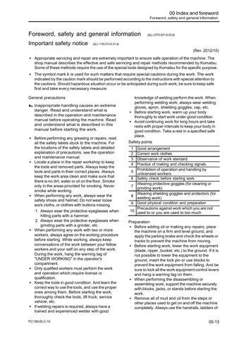
Method of disconnecting and connecting of push-pull type coupler (ALLC930-001-P-00-A)
(Rev. 2012/01)
k Loosen the oil filler cap of the hydraulic tank slowly to release the remaining pressure in the hydraulic tank.
k Even if the remaining pressure is released from the hydraulic tank, some hydraulic oil flows out when the hose is disconnected. Accordingly, prepare an oil container.
Type 1 (ALL-C930-925-P-01-A)

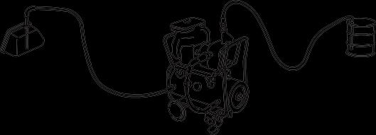
Disconnection
1. Hold adapter (1) and push hose joint (2) into mating adapter (3). (Fig. 1)

a It can be pushed in by approximately 3.5mm.
a Do not hold rubber cap portion (4).
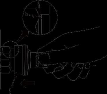
2. While pushing hose joint (2) into adapter (3), push rubber cap (4) against adapter (3) until "click" is heard. (Fig. 2)
3. Hold hose adapter (1) or hose (5) and pull it out. (Fig. 3)
a Since some hydraulic oil flows out, prepare an oil container.
Connection
1. Hold hose adapter (1) or hose (5) and insert it in mating adapter (3) aligning them with each other. (Fig. 4)
a Do not hold rubber cap part (4).
2. After inserting the hose fitting in the adapter on the other side perfectly, pull it back to check the connecting condition. (Fig. 4)
a When the hose fitting is pulled back, the rubber cap will move toward the hose, however, it is not a problem.
00 Index and foreword
00-28 PC138USLC-10
Type 2 (ALL-C930-925-P-02-A)
Disconnection
1. While holding the fitting, push body (7) in straight until sliding prevention ring (6) hits contact surface (a) at the hexagonal part on the male side. (Fig. 6)
2. While keeping the condition of Step 1, turn lever (8) to the right (clockwise). (Fig. 7)


3. While keeping the conditions of Steps 1 and 2, pull out whole body (7) to disconnect it. (Fig. 8)

Connection
1. While holding the fitting, push body (7) in straight until sliding prevention ring (6) hits contact surface (a) at the hexagonal part on the male side to connect it. (Fig. 9)
00 Index and foreword Foreword, safety and general information PC138USLC-10 00-29
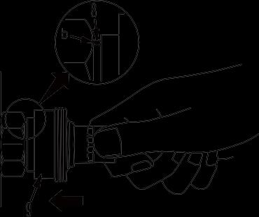
Type 3 (ALL-C930-925-P-03-A)
Disconnection
1. While holding the fitting, push body (9) in straight until sliding prevention ring (8) hits contact surface (b) at the hexagonal portion on the male side. (Fig. 10)
2. While keeping the condition of Step 1, push cover (10) straight until it hits contact surface (b) of the hexagonal portion on the male side. (Fig. 11)
3. While keeping the conditions of Steps 1 and 2, pull out whole body (9) to disconnect it. (Fig. 12)
Connection
1. While holding the fitting, push body (9) in straight until sliding prevention ring (8) hits contact surface (a) at the hexagonal portion on the male side to connect them. (Fig. 13)
and
information 00-30 PC138USLC-10
00 Index and foreword Foreword, safety
general