11 minute read
00 Index and foreword


Foreword, safety and general information
How to read the shop manual (ALL-0320-010-A-01-A)
Advertisement
(Rev. 2012/10)
• Some attachments and optional parts described in this shop manual may not be arranged for certain areas. Contact your Komatsu distributor if one or some of them are required.
• Materials and specifications are subject to change without notice.
• The shop manuals are available for "Machine part" and "Engine part". For the engine, see the shop manual for the same model of the engine as the one which is mounted on the machine.
Composition of shop manual
• This shop manual describes the technical information required for the services performed in a workshop. The shop manual is divided into the following chapters for the convenience of use.
00. Index and foreword
• This section includes the index, foreword, safety and basic information.
01. Specification
• This section explains the specifications of the machine.
10. Structure and function
• This section explains the structure and function of the machine. The section of "Structure and function" serves not only to give an understanding for the structure of each component, but also serves as reference material for troubleshooting.
20. Standard value table
• The standard values for a new machine and trouble shooting are indicated. This standard value table is used for testing and adjusting, and determining a failure at troubleshooting.
30. Testing and adjusting
• This section describes the measuring tools and how to measure, and how to adjust various parts. As for the standard value and failure criterion, see the standard value table.
40. Troubleshooting
• This section describes the troubleshooting in a suspected area when a failure occurs and the remedy for the failure. Troubleshooting is described by each failure mode.
50. Disassembly and assembly
• This section explains the procedures for removing, installing, disassembling, and assembling each part or component and the special tools for the works as well as precautions for doing them safely. In addition, tightening torque, and quantity and weight of coating material, oil, grease, and coolant required for the works are also explained.
60. Maintenance standard
• This section describes the maintenance standard values for each component. This section gives the criterion values for each component and required remedy at disassembly or maintenance.
80. Appendix
• The structure and function, testing and adjusting, and troubleshooting for all of the other components or equipment which can not be separately classified are explained together in the appendix.
90. Diagrams and drawings
• This section gives hydraulic circuit diagrams and electrical circuit diagrams.
Symbol
Important safety and quality portions are marked with the following symbols so that the shop manual is used practically.
Symbol Item k Safety a Caution
4 Weight
3 Tightening torque
2 Coat
5 Oil, coolant
Remarks
The special safety precautions required for performing work are described.
The special technical precautions or other precautions for preserving standards required when performing work are described.
The weight of part or component and the cautions required when selecting hoisting wire or when working posture is important are indicated.
The tightening torques that require special attention during assembly work are indicated.
The places to be coated with adhesives, grease, etc. during assembling are indicated.
The places where oil, coolant, etc. must be added and the quantity to be added are indicated.
�� Drain Places where oil, coolant, etc. must be drained and the quantity to be drained are indicated.
Unit
• In this shop manual, the units are indicated with International System of units (SI).
• For reference, Gravitational System of units which is used to be used is indicated in parentheses of { }.
Explanation of terms for maintenance standard (ALL-0330-006-A-01-A)
(Rev. 2012/10)
• The chapter of maintenance standard shows judgement criteria to determine the products to be replaced or to be reused. The judgement criteria are described by using the following terms.
Standard dimension and tolerance
• To be accurate, the finished dimension of a part is slightly different from one to another.
• The finished dimension of a part specifies the allowable difference from the standard dimension which is set first.
• The dimension set as the standard is called the standard dimension and the range of difference from this standard dimension is called the "tolerance".
• An indication example of a standard dimension and tolerance is shown in the following table. (The standard dimension is entered on the left side and the tolerance is entered with a positive or negative symbol on the right side)
• When some parts are repaired, the value of performance/function is set to the standard value.
• The tolerance may be indicated in the text and a table as "standard dimension (upper limit of tolerance/lower limit of tolerance)."
Example: 120(-0.022/-0.126)
• Usually, the dimension of a hole and the dimension of a shaft to be inserted into the hole are indicated by the same standard dimension and different tolerances of the hole and shaft. The tightness of fit is decided by the tolerance.
• An indication example of a shaft and hole is shown in the following table. (The standard dimension is entered on the left side and the tolerance of the shaft is entered with a positive or negative symbol at the center and that of the hole on the right side)
Standard interference
• When the diameter of a hole of a part shown in the given standard dimension and tolerance table is smaller than that of the shaft to be inserted, the difference between those diameters is called the "interference".
Standard clearance and standard value
• The clearance made when new parts are assembled is called the standard clearance, which is indicated by the range from the minimum clearance to the maximum clearance.
• When some parts are repaired, the clearance is generally adjusted to the standard clearance.
• The values indicating performance and function of new products or equivalent are called the "standard value", which is indicated by a range or a target value.
• Subtract the maximum dimension of the hole from the minimum dimension of the shaft and call it (A). Subtract the minimum dimension of the hole from the maximum dimension of the shaft and call it (B). The range between (A) and (B) is the "standard interference".
• After repairing or replacing some parts, measure the dimension of their hole and shaft and check that the interference is in the standard range.
Repair limit and allowable value or allowable dimension
• The dimensions of parts change because of the wear or deformation while they are used. When the dimension changes exceeding certain value, the parts can not be used any longer. This value is called "repair limit".
• If a part is worn to the repair limit, it must be replaced or repaired.
• The performance and function of the products lower while they are used. When the value of the performance and function lowers exceeding a certain limit and it influences the operation etc., this value is called the allowable value or allowable dimension.
• A product whose dimension is out of the allowable value, must be repaired. However, since the allowable values are generally estimated through various tests or experiences in most cases, the judgement must be made in consideration of the operating condition and customer's requirement.
Allowable clearance
• Parts can be used until the clearance between them is increased to a certain limit. The limit at which those parts cannot be used is called the "allowable clearance".
• If the clearance between the parts exceeds the allowable clearance, they must be replaced or repaired.
Allowable interference
• The allowable maximum interference between the hole of a part and the shaft of another part to be assembled is called the "allowable interference".
• The allowable interference shows the repair limit of the part of smaller tolerance.
• The parts whose interferences are out of the allowable interference must be replaced or repaired.
Handling equipment of fuel system devices (PC-AD00-2A4-K-00-A)
(Rev. 2012/01)
• The common rail fuel injection system (CRI) consists of more precise parts than the parts used in the conventional fuel injection pump and nozzle. If foreign material enters this system, it may cause a failure. Use special care to prevent entry of the foreign material when servicing the fuel system.
Use care for working environment
• Avoid filter change or repairing the machine in rain or high winds, or at places where there is a lot of dust.
Sealing openings
• Plug the pipes and the openings of the components which are removed with the caps, tapes, vinyl bags, etc. to prevent foreign material from entering. Never perform repair works under the condition that the openings are left as they are or plugged with cloths as foreign material may enter or environment may be polluted by the oil leaked. Do not discard the waste oil somewhere or other. Hand it over to your customer for disposal, or dispose it by yourself.
How to clean parts when dirt is stuck
• If any dirt or dust sticks the parts of the fuel system, clean it off thoroughly with clean fuel.
Precautions for replacing fuel filter cartridge
• Be sure to use the Komatsu genuine fuel filter cartridge.
• The common rail fuel injection system (CRI) consists of more precise parts than the parts used in the conventional fuel injection pump and nozzle. In order to prevent foreign material from entering this system, the filter employs a specially high performance of filter element. If a filter element other than the genuine one is used, the fuel system may have a failure. Accordingly, never use such a filter element.
Handling of intake system parts (PC220-A900-2A4-K-00-A)
(Rev.2012/01)
• The Komatsu Variable Geometry Turbocharger (KVGT) consists of more precise parts (variable mechanism) than the parts used in the conventional turbocharger. If foreign material enters this system, it may cause a failure. Use special care to prevent entry of the foreign material when servicing the air intake system.
Be careful of working environment
• Avoid the repair work of the machine in rain or strong wind or at the places where there is a lot of dust.
Sealing openings
• Plug the pipes and the openings of the components which are removed, with the caps, tapes, vinyl bags, etc. to prevent foreign material from entering. Never perform repair works under the condition that the openings are left open or plugged with rag since foreign material may enter.
Handling of hydraulic equipment (ALL-C000-2A4-P-01-A)

(Rev. 2012/10)
• With the increase in pressure and precision of the hydraulic components, the most common cause of a failure is dirt (foreign material) in the hydraulic circuit. Therefore, the special care must be taken when adding hydraulic oil,or when disassembling or assembling the hydraulic components.
Be careful of working environment
• Avoid adding hydraulic oil, replacing filters, or repairing the machine in rain or high winds, or at places where there is a lot of dust.
Disassembly and maintenance work in the field
• When disassembly or maintenance work of the hydraulic is performed in the field, there is danger of dust entering the components. It is also difficult to check the performance of the components after repairs, so it is desirable to use the component exchange service. The disassembly and assembly of the hydraulic components must be performed in the specially arranged dustproof workshop and the performance test of the components must be performed with the special testing equipment.
Preventing intrusion of foreign materials during refilling operations.
• Care must be taken when adding hydraulic oil so that foreign material does not enter. Keep the oil filler port and the area around it, oil supply pump and oil container clean. If an oil cleaning device is used, it is possible to remove the dirt that is collected during storage. It is a surer means.
Plugging of opening (prevention of flowing out of oil)
• Plug the pipes and the openings of the components which are removed (when plugs are not prepared, seal with caps, tapes, vinyl bags, etc.) to prevent entry of foreign material and flowing out of oil. Never leave the openings of the pipes and hoses without being covered or plugged with cloth as foreign material may enter them or environment may be polluted by the oil leaked. Do not discard the waste oil somewhere or other. Hand it over to your customer for disposal, or dispose it by yourself.
Replacing hydraulic oil while its temperature is high
• When the hydraulic oil is warm, it flows easily. In addition, sludge can also be drained from the circuit together with the oil. So, it is better to change the hydraulic oil while it is warm. When changing the hydraulic oil, the old oil must be drained as much as possible. (Drain the oil not only from the hydraulic tank, but also from the filter housing and the drain plug hole in the circuit.) If the old oil is left in the system, the contaminant and sludge in the oil mix with the new oil and shorten the life of the new hydraulic oil.
Flushing operations
• After disassembling the equipment or when changing the hydraulic oil with new one, flush the system to remove the contaminant and sludge left in the hydraulic circuit as well as the oil which includes them. Normally, flushing is performed twice. Primary flushing is performed by use of the flushing oil and the secondary flushing is performed by use of the specified hydraulic oil.
Cleaning operations
• After repairing the hydraulic equipment (pump, control valve, etc.) or when the machine is in operation, perform oil cleaning to remove the sludge or contaminant in the hydraulic oil circuit. The oil cleaning equipment can remove the ultra fine (approximately 3 μm) particles that the filter built in the hydraulic equipment can not remove. So, it is an extremely effective device.
Foreword, safety and general information
Method of disconnecting and connecting of push-pull type coupler (ALLC930-001-P-00-A)
(Rev. 2012/01) k Loosen the oil filler cap of the hydraulic tank slowly to release the remaining pressure in the hydraulic tank. k Even if the remaining pressure is released from the hydraulic tank, some hydraulic oil flows out when the hose is disconnected. Accordingly, prepare an oil container.
Type 1 (ALL-C930-925-P-01-A)
Disconnection
1. Hold adapter (1) and push hose joint (2) into mating adapter (3). (Fig. 1) a It can be pushed in by approximately 3.5mm. a Do not hold rubber cap portion (4).
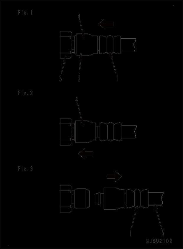
2. While pushing hose joint (2) into adapter (3), push rubber cap (4) against adapter (3) until "click" is heard. (Fig. 2)
3. Hold hose adapter (1) or hose (5) and pull it out. (Fig. 3) a Since some hydraulic oil flows out, prepare an oil container.
Connection
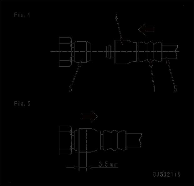
1. Hold hose adapter (1) or hose (5) and insert it in mating adapter (3) aligning them with each other. (Fig. 4) a Do not hold rubber cap part (4).
2. After inserting the hose fitting in the adapter on the other side perfectly, pull it back to check the connecting condition. (Fig. 4) a When the hose fitting is pulled back, the rubber cap will move toward the hose, however, it is not a problem.
Type 2 (ALL-C930-925-P-02-A)
Disconnection
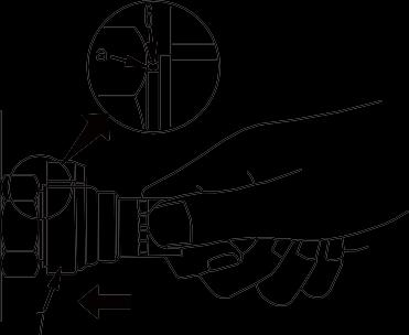
1. While holding the fitting, push body (7) in straight until sliding prevention ring (6) hits contact surface (a) at the hexagonal part on the male side. (Fig. 6)
2. While keeping the condition of Step 1, turn lever (8) to the right (clockwise). (Fig. 7)

3. While keeping the conditions of Steps 1 and 2, pull out whole body (7) to disconnect it. (Fig. 8)

Connection
1. While holding the fitting, push body (7) in straight until sliding prevention ring (6) hits contact surface (a) at the hexagonal part on the male side to connect it. (Fig. 9)