PW160-7K
q This shop manual may contain attachments and optional equipment that are not available in your area. Please consult your local Komatsu distributor for those items you may require. Materials and specifications are subject to change without notice.
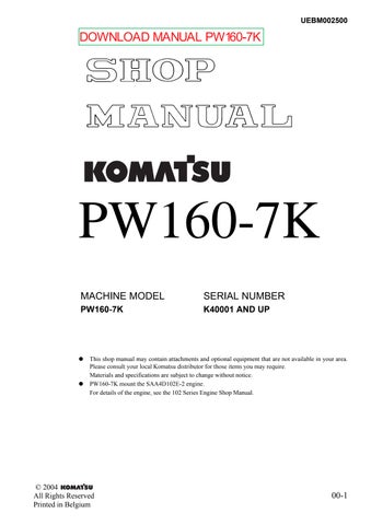
q PW160-7K mount the SAA4D102E-2 engine.
For details of the engine, see the 102 Series Engine Shop Manual.
DOWNLOAD MANUAL
01GENERAL
10STRUCTURE, FUNCTION AND MAINTENANCE STANDARD
20TESTING AND ADJUSTING
30DISASSEMBLY AND ASSEMBLY
90OTHERS
REMOVALANDINSTALLATIONOF ASSEMBLY GOVERNORMOTOR ASSEMBLY
REMOVAL
Disconnect the cable from the negative (-) terminal of the battery.
1.Open engine hood and disconnect governor motor electrical connectors E10 and E11.
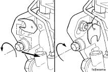
2.Disconnect rod (1) from governor motor (2) by removing rod locking nut (3).
3.Remove governor motor assembly (2) by removing the three securing bolts (4).
INSTALLATIONOFGOVERNORMOTORASSEMBLY
q Carry out installation in the reverse order to removal.
a When installing the governor motor, rotate the shaft by hand to the correct orientationDonotstopthetherodrotationsuddenly.
a Adjust the rod. For details, see TESTING AND ADJUSTING, Testing and adjusting of governor motor lever stroke.

REMOVALANDINSTALLATIONOF ASSEMBLY
REMOVAL
Disconnect the cable from the negative (-) terminal of the battery.
1.Open up the engine hood.
2.Disconnect the two wires from the engine starting motor at:
q Wire (1) and (2) from terminal B.
q Wire (3) from terminal C.

3.Remove two mounting bolts (4) to detach engine starting motor assembly (5).

STARTINGMOTOR ASSEMBLY
INSTALLATION
q Install in reverse order of removal.
Engine starting motor Terminal B
Securing nut: 17.7 to 24.5 Nm (1.8 to 2.5 kgm)
Engine starting motor Terminal C
Securing nut: 2.6 to 4.6 Nm (0.26 to 0.46 kgm)
Both faces of engine starting motor gasket: Gasket sealant (LG-1)
Engine starting motor to Engine Securing Bolt: 43 ± 6 Nm (4.38 ± 0.61 kgm)
REMOVALANDINSTALLATIONOF ASSEMBLY FUELINJECTIONPUMP ASSEMBLY
SPECIALTOOLS
A795-799-1390Pullern1
*Distinction between new and existing
a Disconnect the fuel drain manifold. (A)
a Remove the injection pump supply. (B)
a Remove the high-pressure lines. (C)
a Disconnect the electrical wire to the fuel shutoff valve. (D)
REMOVAL
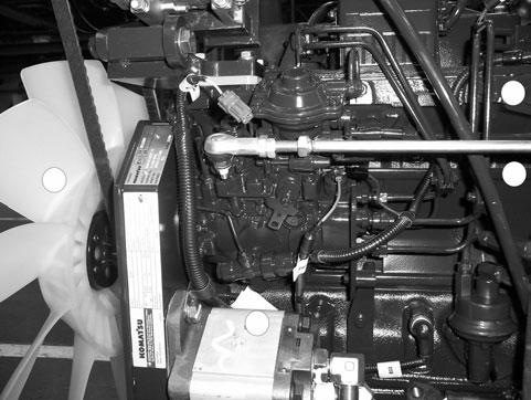
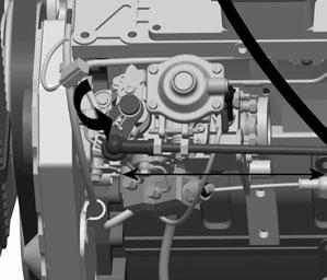
WARNING! Do not remove the control lever. The fuel control lever on the fuel injection pump is indexed to the shaft during pump calibration. If the lever has been removed and reinstalled incorrectly, engine speed and power will be affected.
1.Disconnect all control linkage. Refer to OEM service manual.
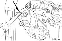
2.Remove the pump support bracket (1).

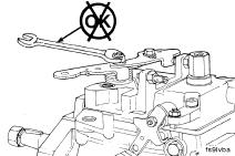
3.Remove the access cap (2), gear retaining nut (3) and washer (4).
4.Locate top dead centre (TDC) for cylinder No.1 by barring engine slowly while pushing in on TDC pin.
See “INSPECTION AND ADJUSTMENT OF FUEL INJECTION TIMING<$paranumonly>-20110
Note:Be sure to disengage the pin after locating TDC.

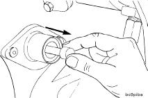
5.The special washer (5) on the fuel injection pump must be removed so the lock screw (6) can be tightened against the driveshaft.
6.Pull the fuel injection pump drive gear loose from the pump driveshaft.

7.Remove the 3 mounting nuts, and take off the fuel injection pump.
8.Remove the gasket, and clean the surface.

Installation
1.Verify cylinder No.1 is at TDC by barring engine slowly while pushing in on TDC pin. See “INSPECTION AND ADJUSTMENT OF FUEL INJECTION TIMING<$paranumonly>-20110
2.Install a new gasket (1).

WARNING! The driveshaft must be clean and free of all oil before installation. Failure to make certain the driveshaft is free of oil can result in the drive gear slipping on the shaft.
3.Install the pump (2).

4.Use your hands to tighten the 3 mounting nuts. Note:Fuel pumps on engines designed to meet Tier 2 industrial emmissions levels have straight holes (not kidney slots) and do not use a timing key.

WARNING! Be sure the timing pin is disengaged before the final torque step to avoid damage to the timing pin.
5.Install the pump driveshaft nut (3) and rotate washer (4). The pump will rotate slightly because of gear helix and clearance. This is acceptable provided the pump is free to move on the flange slots and the crankshaft does not move.
Torque value: 15 - 20Nm

6.If installing the orignal pump, rotate the pump to align the scribe marks.
Torque value: 24Nm

7.If installing a new or rebuilt pump without scribe marks, take up gear lash by rotating the pump against the direction of drive rotation. Tighten the flange mounting nuts.
Torque value: 24Nm

8.Permanently mark the injection pump flange to match the mark on the gear housing.
9.The special washer is wired to the pump and must be installed under the lockscrew.
Torque value: 13Nm

10.Disengage the timing pin before rotating the crankshaft.
11.Install the injection pump support bracket. Finger-tighten all capscrews before final tightening. Note:Tighten the bracket to block mounting capscrew before tightening the bracket to injection pump capscrews.
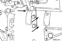
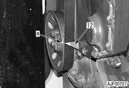
12.Tighten the bracket capscrews to the cylinder block (5). Tighten the tail support bracket capsrew to the fuel pump (6).

13.Tighten the pump retaining nut.
Tightening torque: M14x1.5 nut: 98Nm M12 nut: 93Nm 5 6

14.Install all high-pressure fuel lines and the electrical wire to the fuel shutoff valve. Install drain manifold fitting and reconnect drain tube.

15.When connecting the rod to the control lever, adjust the length so the lever has stop-to-stop movement.
See “Function for Governor Motor Adjustment” on page 20-175.
16.Bleed air from the fuel system and reinstall fan guard as intial machine condition.
REMOVALANDINSTALLATIONOFENGINEFRONTSEAL
Removal
a Disconnect the cable from the negative (–) terminal of the battery.
1.Drain the coolant.
a Drain the coolant to a degree that it will not leak when hose (1) is disconnected.
2.Remove hoses (1) and (2).
3.Remove fan guards (3) and (4).
4.Remove air conditioner compressor belt.[*1]
5.Disconnect connector E06 (16) and remove air conditioner compressor (5) and bracket and move them toward the counterweight.
a Do not separate the air conditioner piping.
6.Remove fan shroud (6).
a Take care that the fan shroud will not interfere with the other parts.
7.Remove the cooling fan.

8.Install lever [1] to tensioner (7) and move the lever in the direction of the arrow to remove fan belt (8).
a Take care not to catch your hands between the tensioner and pulley.
9.Remove fan pulley (9).
10.Remove 4 mounting bolts (10) and crank pulley (11). [*2]
a Remove the crank pulley with its timing mark (a) matched to pointer (12) or make match marks on the crank pulley and front cover so that you can position the crank pulley correctly when installing it.
11.Remove 20 mounting bolts (13) and front cover (14). [*3]
12.Remove engine front seal (15) from front cover (14). [*4]
Installation
q Carry out installation in the reverse order to removal.
[*1]
a Install the air conditioner compressor belt. For details, see TESTING AND ADJUSTING, Inspection and adjustment of air compressor belt tension.
[*2]
a Install the belt to the position from which it was removed.
a Install the crank pulley temporarily and fan belt, and then tighten the mounting bolts to the specified torque.
Mounting bolt: 125 ± 5 Nm {12.75 ± 0.51 kgm}
[*3]
a Apply ThreeBond 1207D or equivalent in the form of a continuous string 1 – 2 mm thick to the fitting face of the front cover.
a Install the gasket to the front cover, and then install them to the engine.
a Tighten the mounting bolts in the following order.
Mounting bolt: 24 ± 4 Nm {2.45 ± 0.41 kgm}
[*4]
a Using the push tool, install so that dimension b will be as follows.
q Dimension b: 21±0.38mm
Removal
1.Remove the hydraulic pump assembly. For details, see Removal and installation of hydraulic pump assembly.
2.Remove damper assembly (1).
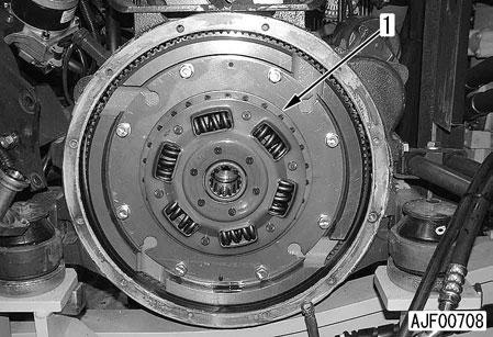
3.Set guide bolts [1] and lift off flywheel assembly (2). [*1]
a Flywheel assembly: 25kg
4.Remove engine rear seal (3). [*2]
a Break the seal carrier with a screwdriver, etc. to remove the seal.
a Take care not to damage the other parts.
a The engine rear seal may be removed according to the following procedure.
1)Make a hole about 3 mm in diameter on the seal with a drill.
2)Attach a dent puller to a slide hammer and insert the hammer into the drilled hole. Then pull out seal (3) by sliding the hammer.
Installation
q Carry out installation in the reverse order to removal.
[*1]
a Tighten the mounting bolts in the following numerical order.
Mounting bolt:
137 ± 7 Nm {13.97 ± 0.71 kgm}
2.Install pilot [2] fitted with engine rear seal (3) in the crankshaft.
[*2]
a Install the engine rear seal according to the following procedure.
1.Install pilot [2] to new engine rear seal (3).
a Before installing the engine rear seal, degrease and dry the seal contact surface of the crankshaft and the lip surface of the seal to prevent oil leakage.
3.Pull out pilot [2].
4.Using the push tool, set the engine rear seal so that dimension "a" will be the following value.
q Dimension a: 25.8mm
a Lightly hit the top, bottom, right, and left of the push tool with a hammer to push in the seal, taking care that the seal carrier will not be bent.
REMOVALANDINSTALLATIONOF ASSEMBLY
SPECIALTOOLS
REMOVAL
a Disconnect the cable from the negative (–) terminal of the battery.
1.Drain the coolant.
2.Close the fuel stop valve.
3.Open the engine hood.
4.Disconnect hose (1) from the engine. [*1]
5.Remove fan guard (2).
6.Remove the air conditioner compressor belt.[*2]
7.Disconnect connector E06 (35), and then remove air conditioner compressor (3) and bracket and move them toward the counterweight.
a Do not separate the air conditioner piping.

8.Disconnect terminal E01 (4) - Grid heater.
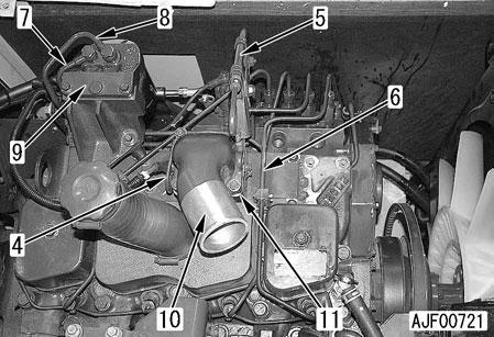
9.Remove the bracket mounting bolts of engine oil level gauge guide (5) and move the level gauge guide.
10.Remove 4 delivery tubes (6).
11.Remove tubes (7) and (8) between fuel filter and fuel injection pump.
12.Remove bracket (9) and fuel filter as a unit. [*3]
13.Remove air intake connector (10) and ribbon heater (11). [*4]
a Cover the openings with adhesive tapes, etc. to prevent foreign matter from entering the engine.
14.Remove heat insulation covers (12) and (13).
15.Remove muffler (14). [*5]

16.Disconnect hoses (15) and (16). [*6]
17.Disconnect tubes (17) and (18). [*7]
18.Remove turbocharger assembly (19). [*8]

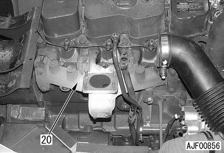
19.Remove exhaust manifold (20). [*9]
20.Referring to REMOVAL AND INSTALLATION OF ENGINE FRONT SEAL, Removal procedure steps 2 – 9, remove the cooling fan pulley.
21.Remove the tensioner.
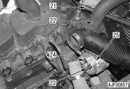
22.Disconnect hoses (21) and (22). [*10]
23.Disconnect terminal B (23) and connector E12 (24).
24.Remove alternator (25) and bracket.
25.Disconnect connector E05 (26) in the rear of the left of the engine.

26.Disconnect sp ill tube (28).
27.Remove 4 nozzle holder assemblies (27).

a If it is difficult to pull the nozzle holder assemblies out of the cylinder head, use tool A2.
a Cover the nozzle holder assembly mounting parts to prevent foreign matter from entering the engine.
28.Remove head cover (29). [*11]
30.Remove push rods (31). [*13]
29.Remove rocker arm assemblies (30). [*12]
a Loosen the locknut and loosen the adjustment screw of each rocker arm 2 – 3 turns.
31.Lift off cylinder head assembly (32). [*14]
Cylinder head assembly: 40kg
32.Remove cylinder head gasket (33).
INSTALLATION
q Carry out installation in the reverse order to removal.
[*1]
Hose clamp:
1st time:10.8 ± 1 Nm {1.1 ± 0.1 kgm}
2nd time: 10.8 ± 1 Nm {1.1 ± 0.1 kgm}
[*2]
a Install the air conditioner compressor belt. For details, see TESTING AND ADJUSTING, Inspection and adjustment of air compressor belt tension.
[*3]
a Apply gasket sealant to the threads of the bolt (only 1 piece) on the head cover side among the 3 fuel filter bracket mounting bolts.
[*8]
[*4]
a Apply gasket sealant to the threads of only the 2 of the air intake connector mounting bolts indicated by the arrows in the following figure

[*5]
a When connecting the exhaust pipe to under the muffler, apply thermosetting sealant (Firegum manufactured by Nihon Holts Co., Ltd. or equivalent) all round the pipe end.
Clamp nut of muffler U-bolt: 9.8 – 14.7 Nm {1.0 – 1.5 kgm}
[*6]
Clamp of hose (15): 10.0 – 11.0 Nm {1.02 – 1.12 kgm}
Clamp of hose (16): 1st time: 10.8 ± 1 Nm {1.1 ± 0.1 kgm} 2nd time: 10.8 ± 1 Nm {1.1 ± 0.1 kgm}
Tube (17): Turbocharger side: 10.3 ± 1.2 Nm {1.1 ± 0.1 kgm}
Cylinder block side: 35 ± 5 Nm {3.6 ± 0.5 kgm}
Tube (18):10 ± 2 Nm {1.0 ± 0.2 kgm}
Mounting nut: 24 ± 4 Nm {2.4 ± 0.4 kgm}
Mounting nut: 24 ± 4 Nm {2.4 ± 0.4 kgm}
[*9] a Tighten the mounting bolts in the following numerical order.
Mounting bolt: 1st time:Tighten all the bolts to: 43 ± 6 Nm {4.38 ± 0.61 kgm}. 2nd time:Tighten only bolts 1 – 4 to: 43 ± 6 Nm {4.38 ± 0.61 kgm}
[*10]
[*11]
Clamp of hose (22): 8.8 ± 0.5 Nm {0.9 ± 0.05 kgm}
Mounting bolt: 24 ± 4 Nm {2.45 ± 0.41 kgm}
12 [*12] [*13] [*14]
a Install the rocker arm assembly and cylinder head assembly according to the following procedure.
a Check that there is not foreign matter on the cylinder head mounting face and in the cylinder.
1)Set cylinder head gasket (33) to the cylinder block.
q Check that the gasket is matched to the holes of the block.
2)Sling cylinder head assembly (32) and set it to the cylinder block.
3)Install push rods (31).
4)Install rocker arm assemblies (30) and tighten mounting bolts (34) with the fingers.
a Check that the balls of adjustment screws (35) are fitted to the sockets of push rods (31).

5)Tighten the cylinder head bolts in the following numerical order in 3 times.
Threads and seat of mounting bolt: Engine oil (SAE15W-40)
Cylinder head bolt:
1st time:Tighten all the bolts to:
90±5Nm{9.18±0.51kgm} in the numerical order shown in the figure.
2nd time:Tighten bolts 3, 6, 11, and 14 to:
120±5Nm{12.24±0.51kgm} in order.
3rd time:Using tool A3, tighten all the bolts by 90° ± 5° in the numerical order shown in the figure. (Angle tightening)
a When not using tool A3 , make marks on the bolts and cylinder head, and then tighten each bolt by the above angle.
6)Tighten rocker arm assembly mounting bolts (34) permanently.
Mounting bolt: 24 ± 4 Nm {2.45 ± 0.41 kgm}

7)Adjust the valve clearance. For details, see TESTING AND ADJUSTING, Adjustment of valve clearance.
q Refilling with water
Add water to the specified level. Run the engine to circulate the water through the system. Then, check the water level again.
Cooling water: Approx. 16.2 l
q Bleeding air
Bleed air from the fuel piping. For details, see REMOVAL AND INSTALLATION OF FUEL INJECTION PUMP ASSEMBLY.