This technical manual is written for an experienced technician and contains sections that are specifically for this product. It is a part of a total product support program.
The manual is organized so that all the information on a particular system is kept together. The order of grouping is as follows:
• Table of Contents
• Specifications
• Component Location
• System Schematic
• Theory of Operation
• Troubleshooting Chart
• Diagnostics
• Tests & Adjustments
• Repair
NOTE: Depending on the particular section or system being covered, not all of the above groups may be used.
Specifications Engine—3TNE75-RJF
Engine—3TNE78-JFM
Steering
Each section will be identified with a symbol rather than a number. The groups and pages within a section will be consecutively numbered.
Miscellaneous
All information, illustrations and specifications in this manual are based on the latest information available at the time of publication. The right is reserved to make changes at any time without notice.
We appreciate your input on this manual. To help, there are postage paid post cards included at the back. If you find any errors or want to comment on the layout of the manual please fill out one of the cards and mail it back to us.
JOHN DEERE COMMERCIAL AND CONSUMER EQUIPMENT DIVISION
Horicon, Wisconsin
All rights reserved
HANDLE FLUIDS SAFELY - AVOID FIRES
PREVENT BATTERY EXPLOSIONS
PREPARE FOR EMERGENCIES.
PREVENT ACID BURNS.
AVOID HIGH-PRESSURE FLUIDS.
PARK MACHINE SAFELY .
SUPPORT MACHINE PROPERLY.
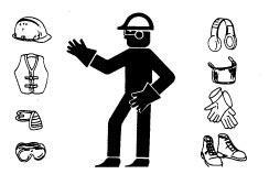
WEAR PROTECTIVE CLOTHING
SERVICE MACHINES SAFELY
WORK IN VENTILATED AREA.
REPLACE SAFETY SIGNS.
USE PROPER LIFTING EQUIPMENT
SERVICE TIRES SAFELY.
AVOID HARMFUL ASBESTOS DUST
WORK IN CLEAN AREA.
USE PROPER TOOLS
DISPOSE OF WASTE PROPERLY
LIVE WITH SAFETY
GENERAL INFORMATION
HANDLE FLUIDS SAFELY - AVOID FIRES
When you work around fuel, DO NOT smoke or work near heaters or other fire hazards.
Store flammable fluids away from fire hazards. DO NOT incinerate or puncture pressurized containers. Make sure machine is clean of trash, grease, and debris.
DO NOT store oily rags, they can ignite and burn spontaneously.
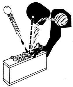
PREVENT BATTERY EXPLOSIONS
Keep sparks, lighted matches, and open flame away from the top of battery. Battery gas can explode.
Never check battery charge by placing a metal object across the posts. Use a volt-meter or hydrometer. DO NOT charge a frozen battery; it may explode. Warm battery to 16°C (60°F).
PREPARE FOR EMERGENCIES
Be prepared if a fire starts.
Keep a first aid kit and fire extinguisher handy. Keep emergency numbers for doctors, ambulance service, hospital, and fire department near your phone.
PREVENT ACID BURNS
Sulfuric acid in battery electrolyte is poisonous. It is strong enough to burn skin, eat holes in clothing, and cause blindness if splashed into eyes.
Avoid the hazard by:
1. Filling batteries in a well-ventilated area.
2. Wearing eye protection and rubber gloves.
3. Avoiding breathing fumes when electrolyte is added.
4. Avoiding spilling or dripping electrolyte.
5. Use proper jump start procedure. If you spill acid on yourself:
1. Flush your skin with water.
2. Apply baking soda or lime to help neutralize the acid.
3. Flush your eyes with water for 10-15 minutes. Get medical attention immediately. If acid is swallowed:
1. Drink large amounts of water or milk.
2. Then drink milk of magnesia, beaten eggs, or vegetable oil.
3. Get medical attention immediately.
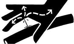
AVOID HIGH-PRESSURE FLUIDS
Escaping fluid under pressure can penetrate the skin causing serious injury.
Avoid the hazard by relieving pressure before disconnecting hydraulic or other lines. Tighten all connections before applying pressure.
Search for leaks with a piece of cardboard. Protect hands and body from high pressure fluids.
If an accident occurs, see a doctor immediately. Any fluid injected into the skin must be surgically removed within a few hours or gangrene may result. Doctors unfamiliar with this type of injury should reference a knowledgeable medical source. Such information is available from Deere & Company Medical Department in Moline, Illinois, U.S.A.
PARK MACHINE SAFELY
Before working on the machine:
• Lower all equipment to the ground.
• Stop the engine and remove the key.
• Disconnect the battery ground strap.
• Hang a “DO NOT OPERATE” tag in operator station.
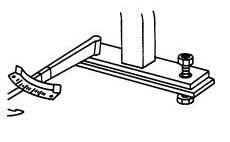
SUPPORT MACHINE PROPERLY
Always lower the attachment or implement to the ground before you work on the machine. If you must work on a lifted machine or attachment, securely support the machine or attachment.
DO NOT support the machine on cinder blocks, hollow tiles, or props that may crumble under continuous load. DO NOT work under a machine that is supported solely by a jack. Follow recommended procedures in this manual.
X9811
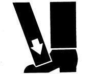
WEAR
Wear close fitting clothing and safety equipment appropriate to the job.
Prolonged exposure to loud noise can cause impairment or loss of hearing.
Wear a suitable hearing protective device such as earmuffs or earplugs to protect against objectionable or uncomfortable loud noises.
Operating equipment safely requires the full attention of the operator. DO NOT wear radio or music headphones while operating machines.
SERVICE MACHINES SAFELY
Tie long hair behind your head. DO NOT wear a necktie, scarf, loose clothing, or necklace when you work near machine tools or moving parts. If these items were to get caught, severe injury could result.
Remove rings and other jewelry to prevent electrical shorts and entanglement in moving parts.
WORK IN VENTILATED AREA
Engine exhaust fumes can cause sickness or death. If it is necessary to run an engine in an enclosed area, remove the exhaust fumes from the area with an exhaust pipe extension.
If you DO NOT have an exhaust pipe extension, open the doors and get outside air into the area.
ILLUMINATE WORK AREA SAFELY
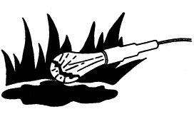
Illuminate your work area adequately but safely. Use a portable safety light for working inside or under the machine. Make sure the bulb is enclosed by a wire cage. The hot filament of an accidentally broken bulb can ignite spilled fuel or oil.
TS206
TS228
TS220
TS223
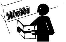
REPLACE SAFETY SIGNS
Replace missing or damaged safety signs. See the machine operator's manual for correct safety sign placement.
USE PROPER LIFTING EQUIPMENT
Lifting heavy components incorrectly can cause severe injury or machine damage.
Follow recommended procedure for removal and installation of components in the manual.
KEEP ROPS INSTALLED PROPERLY
Make certain all parts are reinstalled correctly if the roll-over protective structures (ROPS) is loosened or removed for any reason. Tighten mounting bolts to proper torque.
The protection offered by ROPS will be impaired if ROPS is subjected to structural damage, is involved in an overturn incident, or is in any way altered by welding, bending, drilling, or cutting. A damaged ROPS should be replaced, not reused.
SERVICE TIRES SAFELY
Explosive separation of a tire and rim parts can cause serious injury or death.
DO NOT attempt to mount a tire unless you have the proper equipment and experience to perform the job.
Always maintain the correct tire pressure. DO NOT inflate the tires above the recommended pressure. Never weld or heat a wheel and tire assembly. The heat can cause an increase in air pressure resulting in a tire explosion. Welding can structurally weaken or deform the wheel.
When inflating tires, use a clip-on chuck and extension hose long enough to allow you to stand to one side and NOT in front of or over the tire assembly. Use a safety cage if available.
Check wheels for low pressure, cuts, bubbles, damaged rims or missing lug bolts and nuts.
TS211
AVOID HARMFUL ASBESTOS DUST
Avoid breathing dust that may be generated when handling components containing asbestos fibers. Inhaled asbestos fibers may cause lung cancer.
Components in products that may contain asbestos fibers are brake pads, brake band and lining assemblies, clutch plates, and some gaskets. The asbestos used in these components is usually found in a resin or sealed in some way. Normal handling is not hazardous as long as airborne dust containing asbestos is not generated.
Avoid creating dust. Never use compressed air for cleaning. Avoid brushing or grinding material containing asbestos. When servicing, wear an approved respirator. A special vacuum cleaner is recommended to clean asbestos. If not available, apply a mists of oil or water on the material containing asbestos.
Keep bystanders away from the area.
WORK IN CLEAN AREA
Before starting a job:
• Clean work area and machine.
• Make sure you have all necessary tools to do your job.
• Have the right parts on hand.
• Read all instructions thoroughly; DO NOT attempt shortcuts.
USE PROPER TOOLS
Use tools appropriate to the work. Makeshift tools and procedures can create safety hazards.
Use power tools only to loosen threaded parts and fasteners.
For loosening and tightening hardware, use the correct size tools. DO NOT use U.S. measurement tools on metric fasteners. Avoid bodily injury caused by slipping wrenches.
Use only service parts meeting John Deere specifications.
TS220
T6642EJ
TS779
PTO SYSTEM
Test Conditions:
• Park brake disengaged
• Engine running approximately half throttle
• Deck or PTO driven implement installed
• PTO switch OFF
Test/Check PointNormalIf Not Normal
1. PTO shaftPTO shaft must not be turning.Perform PTO Brake Test.
• PTO switch ON
2. PTO shaft ONPTO must engage with a smooth modulated engagement. PTO engagement pressure in specification.
• Engine at full RPM.
• Shut PTO switch OFF.
3. PTO shaft OFFPTO shaft and implement must stop within 4 seconds.
PTO SYSTEM
Perform PTO Engagement Pressure Test. See Section 8. Inspect PTO solenoid, engagement valve, control valve cover gasket, brake piston cover gasket and top plate gasket, PTO shaft seals, clutch and brake disc.
Check brake springs and brake packing. See Section 6. Repair PTO Inertia Brake.
M47271
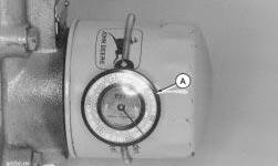
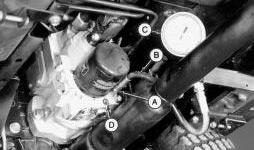
HYDRAULIC OIL WARM-UP PROCEDURE
Reason:
When making hydraulic tests the oil must be heated to the specified temperature for the tests to be accurate.
Equipment
• JDG282 Temperature Gauge
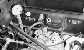
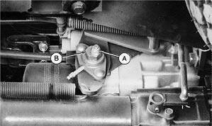
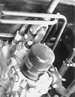
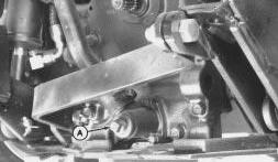
Connections:
1. Install JDG282 Temperature Gauge (A) on transmission oil filter.
2. Put cardboard or paper in front of oil cooler to restrict air flow.
Procedure:
1. Apply park brake. Start engine and run at full throttle.
2. Move and hold hydraulic lever in implement raise position.
3. Periodically cycle all hydraulic functions to distribute heated oil.
4. Heat oil to temperature specified in test.
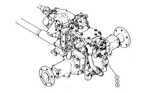
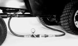
CHARGE PUMP PRESSURE TEST
Reason:
To determine charge pump pressure and to adjust relief valve.
Equipment:
• JT05488 Connector
• JT03017 Hose
• JT03344 Gauge 2000 kPa (20 bar) (300 psi)
c
CAUTION
Escaping fluid under pressure can penetrate the skin causing serious injury. Avoid the hazard by relieving pressure before disconnecting hydraulic or other lines. Tighten all connections before applying pressure. Search for leaks with a piece of cardboard. Protect hands and body from high pressure fluids.
If an accident occurs, see a doctor immediately. Any fluid injected into the skin must be surgically removed within a few hours or gangrene may result. Doctors unfamiliar with this type of injury may call the Deere & Company Medical Department In Moline, illinois, or other knowledgeable medical source.
1. Heat hydraulic oil to specifications. (See procedure in this section.)
2. Operate engine at fast idle.
3. Observe pressure gauge reading.
Specifications:
Hydraulic Oil Temperature
Engine Speed.
Charge Pressure (min.)
Results:
43°C (110°F)
Fast Idle
.968—1379 kPa (140—200 psi)
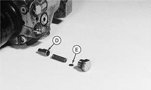
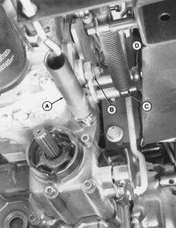
• If pressure is not within specifications, adjust charge relief valve (D) by adding shims (E), then repeat test.
NOTE: One 0.03 mm (.001 in) shim will change charge relief pressure by approximately 7 kPa (1 psi).
• If pressure still is not within specifications, charge pump may be worn or abnormal internal leak within the transmission is suspected. Perform Charge Pump Flow Test. Inspect charge pump first, then internal parts of transmission. Replace as necessary. (See Section 8.)
CHARGE PUMP FLOW TEST
Reason:
To determine condition of the charge pump.
Equipment:
• JT03368 Fittings (2)
• JT05469 Flow meter and Hoses
c CAUTION
Escaping fluid under pressure can penetrate the skin causing serious injury. Avoid the hazard by relieving pressure before disconnecting hydraulic or other lines. Tighten all connections before applying pressure. Search for leaks with a piece of cardboard. Protect hands and body from high pressure fluids.
If an accident occurs, see a doctor immediately. Any fluid injected into the skin must be surgically removed within a few hours or gangrene may result. Doctors unfamiliar with this type of injury may call the Deere & Company Medical Department In Moline, illinois, or other knowledgeable medical source.
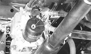
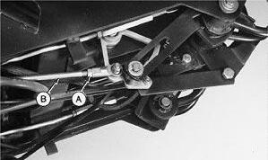
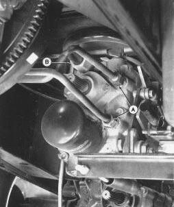
Connections:
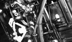
1. Remove cooler lines (A).
2. Remove filter.
M47273
X9811
M47274
3. Install JT03368 Fittings (A) and JT05469 Flowmeter kit.
4. Install filter.
Procedure:
1. Heat hydraulic oil to specifications. (See procedure in this section.)
2. Operate engine at fast idle speed.
3. Observe flowmeter reading.
Specifications:
Hydraulic Oil Temperature
Engine Speed. .
Minimum Pump Flow. .
Results:
43°C (110°F)
.3650 rpm
.15 L/m (4 gpm)
• If flow is less than specifications, inspect charge pump for wear or damage. (See Section 8.)
HYDROSTATIC TRANSMISSION RELIEF VALVE TEST
Reason:
To determine motor relief valve pressure and to help determine internal transmission condition.
Equipment:
• JT05488 Connector
• JT03364 Hose 77,000 kPa (10,000 psi)
• JT03362 Gauge 77,000 kPa (10,000 psi)
c
CAUTION
Escaping fluid under pressure can penetrate the skin causing serious injury. Avoid the hazard by relieving pressure before disconnecting hydraulic or other lines. Tighten all connections before applying pressure. Search for leaks with a piece of cardboard. Protect hands and body from high pressure fluids.
If an accident occurs, see a doctor immediately. Any fluid injected into the skin must be surgically removed within a few hours or gangrene may result. Doctors unfamiliar with this type of injury may call the Deere & Company Medical Department In Moline, illinois, or other knowledgeable medical source.
Perform test in area away from obstacles or bystanders. Unit could unexpectedly move. Block wheels to prevent movement.
Procedure:
1. Heat hydraulic oil to specifications. (See procedure in this section.)
2. Operate engine at fast idle.
3. Depress both turn brake pedals to keep machine from moving.
4. Slowly depress forward or reverse speed control pedal to get a reading.
5. Observe pressure gauge reading.
6. Reconnect brake lock switch.
NOTE: Engine horsepower may not be sufficient to see relief pressure. This test will show a malfunctioning valve, if performance was the complaint.
Specifications:
Hydraulic Oil Temperature
Fast Idle
Relief Pressure.
Results:
43°C (110°F)
3425 ± 100 rpm
. .41370—44817 kPa (8000—6500 psi)
NOTE: Relief cartridge is not adjustable.
• If pressure is not within specifications, inspect relief valve for wear or damage. Replace if necessary. (See Section 8.) Repeat test. If pressure is still low, suspect internal transmission leakage, wear or damage.
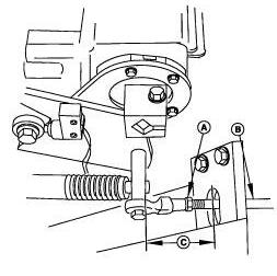
TRANSMISSION FORWARD
ADJUSTMENT
Reason:
To move speed linkage into correct position for maximum forward speed.
Procedure:
1. Set park brake, engine off.
2. Loosen jam nuts (A) on each end of control rod (B).
NOTE: If only a sight adjustment is required, make adjustment by removing front swivel joint, turning joint in or out to change measurement.
3. Push reverse pedal all the way down.
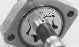
4. Measure the distance (C) between transaxle mounting plate and front of control rod to control plate spacer.
Specification
Distance
.52 mm (2.0 in.)
M47276
M79544
Results:
• Turn control rod to lengthen or shorten, to obtain specified distance.
IMPORTANT: Make sure control rod is centered in ball joint end.
TRANSMISSION NEUTRAL ADJUSTMENT
Reason:
To assure that machine does not creep when pedals are in neutral.
Equipment:
• Hoist
• Jackstands (4)
NOTE: If creep is intermittent, inspect transmission control linkage for wear or damage or neutral return linkage for binding before adjusting transmission neutral.
Procedure:
c
CAUTION
When servicing a MRWD equipped vehicle with front wheels supported off ground and engine running, always support rear wheels in a similar manner. The MRWD is always engaged and will push vehicle off supports if wheels are not raised.
1. Lift machine with a hoist and support both front and rear wheels off the ground.
2. Put jackstands under frame and rear axle.
Procedure continued:
c CAUTION
Use extreme caution when doing this adjustment. Drive wheels are free to spin.
4. Have someone push down center of seat cushion to activate seat safety switch, or use a jumper wire to bypass the seat switch.
5. Start engine and run at low idle. Put transaxle in Hi range.
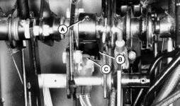
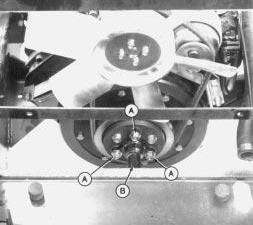
6. With brakes disengaged, turn eccentric nut (B) forward and backward until drive wheels stop turning.
NOTE: Eccentric nut must be positioned rearward and eccentric positioned forward for correct adjustment.
7. Hold adjustment and tighten lock nut (A). Make sure adjustment did not change.
8. Put transaxle shift lever in neutral. Depress both forward and reverse speed pedals then release.
9. Put transaxle in Hi range. Check neutral adjustment. Repeat adjustment as necessary.
c
CAUTION
Remove jumper wire from seat switch if installed.
10. Lower machine to the ground. Remove seat switch jumper wire if used.
Results:
• If drive wheels continue to turn, check for worn or binding neutral return linkage or too light of tension on neutral return spring. Check neutral return adjustment.
3. Loosen lock nut (A).
TRANSMISSION NEUTRAL RETURN ADJUSTMENT
Reason:
To assure that the transmission always returns to neutral at the desired rate when the pedals are released.
Procedure:
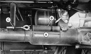
1. With machine in neutral, check that dimension (A) ACROSS THE COILS ONLY on the neutral return spring (B) is 133 mm (5.24 in.). DO NOT allow spring coil length to drop below 120 mm (4.72 in.).
NOTE: This dimension is only an initial setting. Length may vary with operator preference.
2. Start engine at fast idle and operate speed controls.
Results:
IMPORTANT: If linkage is too loose, speed control pedals may not return to neutral.
• If transmission does not return to neutral or returns too slowly, tighten nut (C) to increase tension on return linkage.
• If transmission returns to neutral too fast, loosen nut (C) to decrease tension on return linkage. Repeat test several times to make sure transmission will return to neutral.
CRUISE CONTROL LINKAGE
ADJUSTMENT
Reason:
To assure that cruise control will engage and disengage properly.
Procedure:
1. Put service-park brake in disengaged position, transaxle in neutral.
2. With engine not running, push down forward drive pedal and engage cruise control. Drive pedal should remain in down position.
3. Engage service-park brake. Forward drive pedal should disengage.
Results:
• If cruise control slips or does not engage, disconnect link (A) and turn clockwise as necessary for a smooth engagement.
• If drive pedal sticks or does not disengage when service-park brake is engaged, disconnect link (A) and turn counterclockwise as necessary for smooth disengagement.
SERVICE—PARK BRAKE SWITCH ADJUSTMENT
Reason:
To make sure switch plunger is being completely depressed and that lever is not resting against switch body.
M47278
M79534
Procedure:
1. With service-park brake pedal disengaged, stop (B) should depress switch plunger (C).
Results:
• If switch is not depressed, loosen set screw (A) and move stop against switch so plunger is all the way in but not against the switch housing. Tighten set screw.
HYDROSTATIC TRANSMISSION REPAIR
SERVICE EQUIPMENT AND TOOLS
NOTE: Order tools from the U.S. SERVICE-GARD Catalog or from the European Microfiche Tool Catalog (MTC). Some tools may be available from a local supplier.
NameUse
Bushing, Bearing,To service bearings and Seal Driver Setand seals.
Internal, 2-Jaw Slide To remove bearings. Hammer Puller
Knife-Edge PullerTo remove bearings.
Hydraulic PressTo service bearings.
Snap Ring Pliers SetTo remove snap rings.
Overhead HoistTo remove hydrostatic transmission.
#8 - 32 x 1 UNC-28 Cap ScrewTo remove hydro motor bearings retaining pin.
SERVICE PARTS KITS
The following kits are available through your parts catalog:
Charge Relief Valve Shim Pack Kit
Implement Relief Valve Shim Pack Kit
REMOVE DRIVE SHAFT— HYDROSTATIC TRANSMISSION
1. Remove three cap screws (A) from drive shaft (B) at engine coupler.
M79535
M79296
2. Loosen two cap screws and nuts (C).
3. Push driveshaft (B) forward on charge pump input shaft to separate the shaft from the recess of the engine coupler.
4. Remove driveshaft from charger pump input shaft.
INSTALL DRIVE SHAFT— HYDROSTATIC TRANSMISSION
1. Put drive shaft on transmission charge pump input shaft.
2. Install other end of drive shaft into recess of engine coupler. Align shaft mounting holes with coupler holes as you install drive shaft.
4. Fasten other end of drive shaft to charge pump input shaft with cap screws and nuts (C). Install cap screws from opposite directions to help maintain balance. Tighten to 60 N·m (45 lb-ft)
M79297
3. Fasten drive shaft (B) to engine with three long cap screws (A). Tighten cap screws to 49 N·m (36 lbft)
M79296
M79297
REMOVE AND INSTALL DRIVE SHAFT—MECHANICAL REAR WHEEL
DRIVE (MRWD)
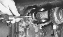
1. Loosen clamps. Slide front and rear covers away from universal joints.
2. Drive pin out of front universal joint to remove shaft.
3. To install, align pin holes of drive shaft front U-joint and MRWD input shaft as you slide the shaft into position.
4. Fasten with spring pin removed earlier.
5. Fasten front cover in place with band clamps.
6. Fasten rear U-joint to drive shaft to transaxle output shaft.
7. Fasten rear cover in places with band clamps.
REMOVE AND INSTALL HYDROSTATIC TRANSMISSION CHARGE PUMP
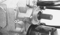
IMPORTANT: Orientation of charge pump - flat surface (A) on charge pump housing must be on left-hand side of the transmission. If turned 180° to the opposite side, pump will not function - no charge pressure will be generated.
IMPORTANT: DO NOT lose small round key (C) that drives the inner gear of the charge pump. It may fall out when you remove the charge pump assembly from the input shaft.
1. Remove two cap screws (B) to remove charge pump. Look to see if small round key (C) is still in keyway of input shaft.
2. Remove round key (C). Inspect key and input shaft for damage or wear. Replace if necessary.
3. Inspect machined surfaces of charge pump and transmission center section for severe scoring. If scoring is noted, replace charge pump and center section.
4. Clean and dry all parts. Machined surfaces must be clean and smooth.
5. Apply clean transmission oil on all internal parts.
6. Apply petroleum jelly to round key (C) and input shaft keyway to hold key in place during installation of charge pump.
M79570
M79571
M79311
M79718
7. Be sure pump O-ring is seated in its groove.
8. Install charge pump on transmission with flat surface (A) on left-hand side. Tighten two cap screws (B) to 37—50 N·m (27—37 lb-ft)
REMOVE HYDROSTATIC TRANSMISSION
NOTE: Use shop cloths or paper towels to catch and clean-up any spilled oil immediately. Cap-off or plug all ports and lines.
1. Remove plug (A) to drain transaxle. Plug is located under the operator's station at the front of the unit. Oil capacity is approximately 17 L (4.5 gal)
2. Remove drive shaft, see REMOVE DRIVE SHAFT—HYDROSTATIC TRANSMISSION earlier in this section.
4. Disconnect suction line (B).
5. Disconnect neutral return spring (A).
6. Remove eccentric/cam follower assembly (B) from carriage bolt of mounting bracket.
3. Remove oil cooler lines (A). Lines are located below the radiator area.
M79704
M79705
M79706
NOTE: Transaxle removed for clarity purposes only.
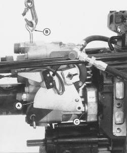
9. Remove swashplate bracket (A).
10. Install eyebolt (B) in threaded hole on top of hydro and attach overhead hoist. Take the slack out of the chain.
11. Have a clean oil pan and shop cloth ready to catch and clean-up any oil.
12. Remove cap screw and flat washer (C) from each side.
13. Separate the transmission from the transaxle. Clean-up and spilled oil immediately. Thoroughly clean outside surface of transmission using wire brush and solvent.
14. Move transmission to a workbench and put it in a clean oil pan.
15. Remove oil filter and wipe-up any spilled oil.