
M n od anual Description
Brakes John deere 1435 Download
This technical manual is written for an experienced technician and contains sections that are specifically for this product. It is a part of a total product support program. The manual is organized so that all the information on a particular system is kept together. The order of grouping is as follows:
• Table of Contents
• Specifications and Information
• Identification Numbers
• Tools and Materials
• Component Location
• Schematics and Harnesses
• Theory of Operation
• Operation and Diagnostics
• Diagnostics
• Tests and Adjustments
• Repair
• Other NOTE: Depending on the particular section or system being covered, not all of the above groups may be used.
The bleed tabs for the pages of each section will align with the sections listed on this page. Page numbering is consecutive from the beginning of the Safety section through the last section.
We appreciate your input on this manual. If you find any errors or want to comment on the layout of the manual please contact us.
Safety
All information, illustrations and specifications in this manual are based on the latest information at the time of publication. The right is reserved to make changes at any time without notice.
COPYRIGHT© 2002
Deere & Co.
John Deere Worldwide Commercial and Consumer Equipment Division
All rights reserved
Previous Editions
COPYRIGHT©
Engine (3TNE88)
/ 3TNE78)


Recognize Safety Information
SAFETY
Handle Fluids Safely - Avoid Fires
Be Prepared For Emergencies


This is the safety-alert symbol. When you see this symbol on your machine or in this manual, be alert to the potential for personal injury.
Follow recommended precautions and safe servicing practices.
Understand Signal Words
A signal word - DANGER, WARNING, or CAUTIon - is used with the safety-alert symbol. DANGER identifies the most serious hazards.
DANGER or WARNING safety signs are located near specific hazards. General precautions are listed on CAUTIon safety signs. CAUTIon also calls attention to safety messages in this manual.
Replace Safety Signs
Replace missing or damaged safety signs. See the machine operator’s manual for correct safety sign placement.
• When you work around fuel, do not smoke or work near heaters or other fire hazards.
• Store flammable fluids away from fire hazards. Do not incinerate or puncture pressurized containers.
• Make sure machine is clean of trash, grease, and debris.
• Do not store oily rags; they can ignite and burn spontaneously.
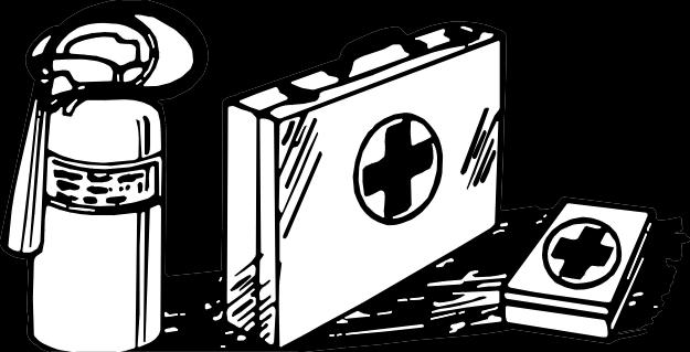
• Be prepared if a fire starts.
• Keep a first aid kit and fire extinguisher handy.
• Keep emergency numbers for doctors, ambulance service, hospital, and fire department near your telephone.
Use Care In Handling and Servicing Batteries
MIF
MIF
MIF
SAFETY
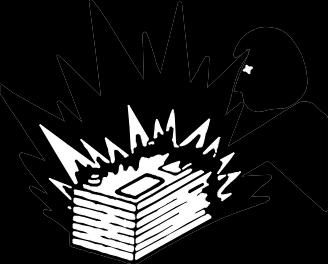
Prevent Battery Explosions
• Keep sparks, lighted matches, and open flame away from the top of battery. Battery gas can explode.
• Never check battery charge by placing a metal object across the posts. Use a volt-meter or hydrometer.
• Do not charge a frozen battery; it may explode. Warm battery to 16°C (60°F).
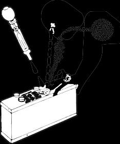
Prevent Acid Burns
• Sulfuric acid in battery electrolyte is poisonous. It is strong enough to burn skin, eat holes in clothing, and cause blindness if splashed into eyes.
Avoid acid burns by:
1. Filling batteries in a well-ventilated area.
2. Wearing eye protection and rubber gloves.
3. Avoiding breathing fumes when electrolyte is added.
4. Avoiding spilling or dripping electrolyte.
5. Use proper jump start procedure.
If you spill acid on yourself:
1. Flush your skin with water.
2. Apply baking soda or lime to help neutralize the acid.
3. Flush your eyes with water for 10 - 15 minutes.
4. Get medical attention immediately.
If acid is swallowed:
1. Drink large amounts of water or milk.
2. Then drink milk of magnesia, beaten eggs, or vegetable oil.
3. Get medical attention immediately.
Wear Protective Clothing


Wear close fitting clothing and safety equipment appropriate to the job.
Prolonged exposure to loud noise can cause impairment or loss of hearing. Wear a suitable hearing protective device such as earmuffs or earplugs to protect against objectionable or uncomfortable loud noises.
Operating equipment safely requires the full attention of the operator. Do not wear radio or music headphones while operating machine.
Use Care Around High-Pressure Fluid Lines
Avoid High-Pressure
Fluids
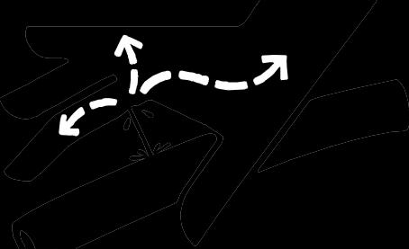
Escaping fluid under pressure can penetrate the skin causing serious injury.
Avoid injury from escaping fluid under pressure by stopping the engine and relieving pressure in the system before disconnecting or connecting hydraulic or other lines. Tighten all connections before applying pressure.
Search for leaks with a piece of cardboard. Protect hands and body from high pressure fluids.
If an accident occurs, see a doctor immediately. Any fluid injected into the skin must be surgically removed within a few hours or gangrene may result. Doctors unfamiliar with this type of injury should reference a knowledgeable medicalsource. Such information is available from Deere & Company Medical Department in Moline, Illinois, U.S.A.
Avoid Heating Near Pressurized Fluid Lines

Flammable spray can be generated by heating near
pressurized fluid lines, resulting in severe burns to yourself and bystanders. Do not heat by welding, soldering, or using a torch near pressurized fluid lines or other flammable materials. Pressurized lines can be accidentally cut when heat goes beyond the immediate flame area.
Service Machines Safely
SAFETY
Support Machine Properly and Use Proper Lifting Equipment


Tie long hair behind your head. Do not wear a necktie, scarf, loose clothing, or necklace when you work near machine tools or moving parts. If these items were to get caught, severe injury could result.
Remove rings and other jewelry to prevent electrical shorts and entanglement in moving parts.
Use Proper Tools
Use tools appropriate to the work. Makeshift tools and procedures can create safety hazards. Use power tools only to loosen threaded parts and fasteners. For loosening and tightening hardware, use the correct size tools. Do not use U.S. measurement tools on metric fasteners. Avoid bodily injury caused by slipping wrenches. Use only service parts meeting John Deere specifications.
Park Machine Safely
Before working on the machine:
1. Lower all equipment to the ground.
2. Stop the engine and remove the key.
3. Disconnect the battery ground strap.
4. Hang a “Do Not Operate” tag in operator station.

If you must work on a lifted machine or attachment, securely support the machine or attachment.
Do not support the machine on cinder blocks, hollow tiles, or props that may crumble under continuous load. Do not work under a machine that is supported solely by a jack. Follow recommended procedures in this manual.
Lifting heavy components incorrectly can cause severe injury or machine damage. Follow recommended procedure for removal and installation of components in the manual.
Work In Clean Area
Before starting a job:
1. Clean work area and machine.
2. Make sure you have all necessary tools to do your job.
3. Have the right parts on hand.
4. Read all instructions thoroughly; do not attempt shortcuts.
Using High Pressure Washers
Directing pressurized water at electronic/electrical components or connectors, bearings, hydraulic seals, fuel injection pumps or other sensitive parts and components may cause product malfunctions. Reduce pressure and spray at a 45 to 90 degree angle.
Illuminate Work Area Safely
Illuminate your work area adequately but safely. Use a portable safety light for working inside or under the machine. Make sure the bulb is enclosed by a wire cage. The hot filament of an accidentally broken bulb can ignite spilled fuel or oil.
MIF
MIF
SAFETY
Work In Ventilated Area
Engine exhaust fumes can cause sickness or death. If it is necessary to run an engine in an enclosed area, remove the exhaust fumes from the area with an exhaust pipe extension.
If you do not have an exhaust pipe extension, open the doors and get outside air into the area.
Warning: California Proposition 65 Warning
Gasoline engine exhaust from this product contains chemicals known to the State of California to cause cancer, birth defects, or other reproductive harm. Diesel engine exhaust and some of its constituents are known to the State of California to cause cancer, birth defects, and other reproductive harm.
Remove Paint Before Welding or Heating
Avoid potentially toxic fumes and dust. Hazardous fumes can be generated when paint is heated by welding, soldering, or using a torch. Do all work outside or in a well ventilated area. Dispose of paint and solvent properly. Remove paint before welding or heating: If you sand or grind paint, avoid breathing the dust. Wear an approved respirator. If you use solvent or paint stripper, remove stripper with soap and water before welding. Remove solvent or paint stripper containers and other flammable material from area. Allow fumes to disperse at least 15 minutes before welding or heating.
Avoid Harmful Asbestos Dust
Avoid breathing dust that may be generated when handling components containing asbestos fibers. Inhaled asbestos fibers may cause lung cancer. Components in products that may contain asbestos fibers are brake pads, brake band and lining assemblies, clutch plates, and some gaskets. The asbestos used in these components is usually found in a resin or sealed in some way. Normal handling is not hazardous as long as airborne dust containing asbestos is not generated.
Avoid creating dust. Never use compressed air for cleaning. Avoid brushing or grinding material containing asbestos. When servicing, wear an approved respirator. A special vacuum cleaner is recommended to clean asbestos. If not available, apply a mist of oil or water on the material containing asbestos. Keep bystanders away from the area.
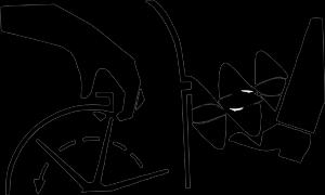
Service Tires Safely
Explosive separation of a tire and rim parts can cause serious injury or death.
Do not attempt to mount a tire unless you have the proper equipment and experience to perform the job.
Always maintain the correct tire pressure. Do not inflate the tires above the recommended pressure. Never weld or heat a wheel and tire assembly. The heat can cause an increase in air pressure resulting in a tire explosion. Welding can structurally weaken or deform the wheel.
When inflating tires, use a clip-on chuck and extension hose long enough to allow you to stand to one side and not in front of or over the tire assembly. Use a safety cage if available.
Check wheels for low pressure, cuts, bubbles, damaged rims or missing lug bolts and nuts.
MIF
SAFETY
Avoid Injury From Rotating Blades, Augers and PTO Shafts


Keep hands and feet away while machine is running. Shut off power to service, lubricate or remove mower blades, augers or PTO shafts.
Service Cooling System Safely

Explosive release of fluids from pressurized cooling system can cause serious burns.
Shut off machine. Only remove filler cap when cool enough to touch with bare hands. Slowly loosen cap to first stop to relieve pressure before removing completely.
Handle Chemical Products Safely


Direct exposure to hazardous chemicals can cause serious injury. Potentially hazardous chemicals used with John Deere equipment include such items as lubricants, coolants, paints, and adhesives.
A Material Safety Data Sheet (MSDS) provides specific details on chemical products: physical and health hazards, safety procedures, and emergency response techniques. Check the MSDS before you start any job using a hazardous chemical. That way you will know exactly what the risks are and how to do the job safely. Then follow procedures and recommended equipment.
Dispose Of Waste Properly
Improperly disposing of waste can threaten the environment and ecology. Potentially harmful waste used with John Deere equipment include such items as oil, fuel, coolant, brake fluid, filters, and batteries. Use leakproof containers when draining fluids. Do not use food or beverage containers that may mislead someone into drinking from them. Do not pour waste onto the ground, down a drain, or into any water source. Inquire on the proper way to recycle or dispose of waste from your local environmental or recycling center, or from your John Deere dealer.
Live With Safety


Before returning machine to customer, make sure machine is functioning properly, especially the safety systems. Install all guards and shields.
MIF
MIF
MIF
Component Location
BRAKES COMPONENT LOCATION
Brake System Component Location

A - Turnbuckle


B - Brake Link Assembly
C - Right Turn Brake Pedal
D - Left Turn Brake Pedal
E - Neutral Safety Arm
F - Neutral Safety Link
G - Support Bracket
H - Master Brake Pedal


MX5550 I - Park Lock Assembly
J - Brake Pedal Shaft
K - Axle Shaft
L - Friction Disk (2 used)
M - Separator Plate (2 used)
N - Actuator Lever
O - Return Spring
P - Brake Pedal Shaft Bushing (2 used)
BRAKES THEORY OF OPERATION
Theory of Operation
Brake System Operation
Function:
To provide a means of stopping the machine and to prevent the machine from moving when not in use.
Theory of Operation:
The brake system consists of plates and disks located inside the axle housing on each side of the transaxle assembly.
The brakes are activated by a common pedal hooked to linkage connected to the individual brake assemblies located in each of the axle shaft housings. The brakes may be activated individually by depressing either the left turn brake pedal or the right turn brake pedal.
Inside each axle shaft housing, the brake components consist of a brake actuator lever/cam, actuator plate, and pairs of alternating friction disks and separator plates.
The brake actuator plate is mounted on six steel balls, which ride inside pockets with ramps on the actuator plate.
The brake friction disks are splined to the axle shafts. The separator plates are keyed to the brake actuator lever/cam shaft and cannot move.
When the brake pedal is depressed, the brake actuator lever/cams rotate, forcing the brake actuator plate to rotate.
As the actuator plate rotates, the ramps on the plate will allow the plate to ride up, forcing the plate against the friction disks and separator plates, causing drag and slowing the machine.
When the pedal is released, the return springs return the brake actuator lever/cams to the rest position, allowing the actuator plates to release the pressure on the friction disks and separator plates.
The machine is equipped with a park brake lock. When the brake pedal is depressed and held, and the park brake lock lever is pulled up, a pawl engages with the teeth on the pivot shaft, locking the brake linkage.
BRAKES DIAGNOSTICS
Diagnostics
Machine Will Not Move
NOTE: This condition may be caused by systems other than brakes. Check the power train system if the following conditions do not correct the problem.
Test Conditions:
• Machine parked safely.
• Park brake released.
Check park brake lock lever assembly for wear or damage. Lever moves freely. Go To Next Step.
• Park brake lock lever assembly is worn or damaged. Repair or replace as necessary.
Check brake linkage adjustment. (See “Adjusting Brakes:” on page 688 in this section.)
Linkage is properly adjusted. Go To Next Step.
• Linkage needs adjustment. (See “Adjusting Brakes:” on page 688 in this section.)
Check condition of brake return springs. Springs must not be stretched, broken, or missing.
• Springs are damaged or missing. Replace springs as necessary.
Brake Will Not Engage or Hold Machine
Test Conditions:
• Machine parked safely.
Check brake linkage adjustment. (See “Adjusting Brakes:” on page 688 in this section.)
Linkage is properly adjusted. Go To Next Step.
• Linkage needs adjustment. (See “Adjusting Brakes:” on page 688 in this section.)
Check brake friction disks for wear or damage. Friction disks are not worn or damaged. Go To Next Step.
• Friction disks are worn or damaged. Replace as necessary.
Check brake separator plates for wear or damage. Separator plates must not be worn or damaged.
• Separator plates are worn or damaged. Replace as necessary.
BRAKES DIAGNOSTICS
Excessive Brake Wear
Test Conditions:
• Machine parked safely.
Check brake pedal shaft and bushings for wear or damage. Shaft moves freely. Go To Next Step.
• Shaft is worn or damaged. Repair or replace as necessary.
Check park brake lock lever assembly for wear or damage. Lever moves freely. Go To Next Step.
• Park brake lock lever assembly is worn or damaged. Repair or replace as necessary.
Check condition of brake return springs. Springs are not stretched, broken, or missing. Go To Next Step.
• Springs are damaged or missing. Replace springs as necessary.
Check brake separator plates for wear or damage. Plates must not be worn or damaged.
• Plates are worn or damaged. Replace as necessary.
Machine Pulls to One Side
NOTE: This condition may be caused by systems other than brakes. Check the power train system if the following conditions do not correct the problem.
Test Conditions:
• Machine parked safely.
• Park brake released.
Check brake linkage adjustment. (See “Adjusting Brakes:” on page 688 in this section.)
Linkage is properly adjusted. Go To Next Step.
• Linkage needs adjustment. (See “Adjusting Brakes:” on page 688 in this section.)
Check park brake lock lever assembly for wear or damage. Lever moves freely. Go To Next Step.
• Park brake lock lever assembly is worn or damaged. Repair or replace as necessary.
Check condition of brake return springs. Springs are not stretched, broken, or missing. Go To Next Step.
• Springs are damaged or missing. Replace springs as necessary.
Check brake friction disks for wear or damage. Friction disks are not worn or damaged. Go To Next Step.
• Disks are worn or damaged. Replace as necessary.
Check brake separator plates for wear or damage. Separator plates must not be worn or damaged.
• Plates are worn or damaged. Replace as necessary.
BRAKES TESTS AND ADJUSTMENTS
Tests and Adjustments
Turn Brake Adjustment
Checking Turn Brake Pedal Free Play:
1. Park machine on level ground.
2. Unlock park brake.


3. Place a piece of tape (A) on the front surface of each turn brake pedal and extending below the floor (C).
4. Make a mark (B) at the same height of the floor on the tape.
6. Release brake pedal and measure the distance (E) between the front edge of the marks on the tape to determine pedal travel.
7. Repeat steps 3 - 6 for the other turn brake pedal.
8. If brake pedal travel is greater than 30 mm, the brakes require adjustment.
Adjusting Brakes:

1. Using tape installed earlier, make two marks (A) at 25 mm and 30 mm above the floor.


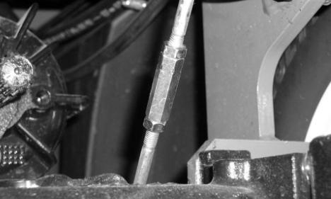
2. Loosen lock nuts (B), and adjust turnbuckle (C) until brake begins to engage when the pedal is between the 25 mm and 30 mm marks on the tape.
3. Repeat for other pedal, keeping left and right side pedals adjusted evenly.
4. Tighten turnbuckle lock nuts.
5. Press turn brake pedal until brake engages. Mark
5. If brakes cannot be adjusted within the range of the turnbuckles, check the transaxle brake plates and disks. position of floor (D) on tape.
MX5609
MX5610
MX5610
MX5611
BRAKES TESTS AND ADJUSTMENTS
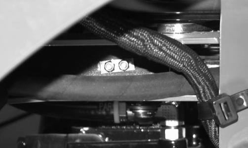
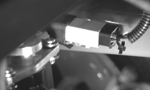
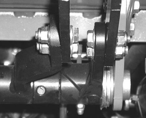
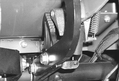
Brake Switch Adjustment
Inspection:
1. Park machine on level surface.
2. Unlock park brake.
3. Disconnect battery negative (-) cable.
4. Open service hatch.
5. Inspect brake switch. If boot, plunger and brake switch are worn or damaged, replace brake switch.

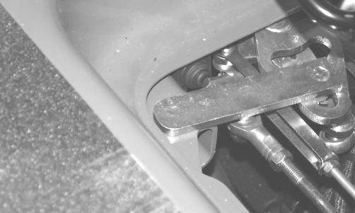


6. Depress master brake pedal. Plunger on brake switch (A) should extend when mixer (B) and neutral safety arm (C) are activated.
7. Release master brake pedal. Plunger on brake switch should retract completely when neutral safety arm is activated by neutral safety link (D) and ball joint (E).
Adjustment:
IMPORTANT: Avoid damage! Improper adjustment may cause damage to plunger and brake switch. Adjust brake switch with park brake lock lever in unlocked position and brakes disengaged.


2. Move brake switch (C) toward front of machine until plunger is fully retracted when contacting neutral safety arm.
3. Tighten screw (D) and lock nut.
4. Depress master brake pedal and release. Ensure that neutral safety arm properly contacts plunger. Adjust if necessary.
5. Check brake switch for proper operation:
a. Operate machine with PTO switch in on position.
b. While depressing master brake pedal, ensure PTO disengages.
c. Adjust or replace brake switch if necessary.
Removal:


1. Loosen lock nut (A) and washer (B) on inside of frame rail.
1. Disconnect connector (A) on back of brake switch.
2. Remove screw, lock nut and brake switch from machine.
3. Replace brake switch.
Installation:
• Installation is done in the reverse order of removal.
• Perform steps 2 - 5 in Adjustment section.
• Check brake switch for proper operation.
MX5622
MX5623
MX5624
MX5624
BRAKES REPAIR
Repair
Brake Linkage Removal and Installation


A - Left Turn Brake Arm
B - Right Turn Brake Arm
C - Center Support
D - Master Brake Pedal Support
E - Right Master Brake Arm
F - Support (2 used)
G - Pedal Shaft
H - Bushing (2 used)
I - Upper Brake Link Assembly (2 used)
J - Turnbuckle (2 used)
K - Lower Brake Link Assembly (2 used)
L - Right Brake Cam Arm
M - Brake Return Spring (2 used)
N - Left Brake Cam Arm
O - Left Master Brake Arm
Brakes John deere
MX5607
Removal:
1. Park machine on level ground.
2. Raise machine and remove front wheels.
BRAKES REPAIR
3. Remove left brake return spring (M) from latch hook.
4. Remove cotter pin and clevis pin holding upper left brake link assembly (I) to left master brake arm (O) and left turn brake arm (A).
5. Remove cotter pin and clevis pin holding left lower brake link assembly (K) to left brake cam arm (N) and remove assembly (I, J, and K).
6. Remove right brake return spring (M) from latch hook.
7. Remove cotter pin and clevis pin holding upper right brake link assembly (I) to right master brake arm (E) and right turn brake arm (B).
8. Remove cotter pin and clevis pin holding right lower brake link assembly (K) to right brake cam arm (N) and remove assembly (I, J, and K).
9. Inspect brake link assemblies and turnbuckles for wear and damage. Replace as necessary.
Installation:
1. Install lock nuts on upper and lower brake link rods and connect with turnbuckle. Adjust assembled linkage to a preset length of 34.3 cm (13.5 in.)
NOTE: The lower right side clevis pin should be installed with its head facing outward. Place a washer between the clevis and rue pin.
2. Install brake link assembly on machine starting with lower clevis first, then upper clevis.
3. Install the brake return springs.
4. Check the left and right turn pedal free play and adjust turn brake linkage. (See “Turn Brake Adjustment” on page 688 in this section.)
BRAKES REPAIR
Turn Brake Pedals Removal and Installation


Brakes John deere
MX5614
A - Right Turn Brake Arm
B - Pedal Shaft
C - Drilled Clevis Pin (2 used)
D - Clevis (2 used)
E - Cotter Pin (2 used)
F - Turnbuckle (2 used)
G - Jam Nut, M8 (2 used)
H - Brake Return Spring (2 used)
I - Screw, M8 x 25 (2 used)
J - Support
K - Lock Nut, M8 (2 used)
L - Pivot Bushing
M - Lock Nut, M8 (4 used)
N - Left Turn Brake Pedal Pad
O - Left Turn Brake Pedal
P - Lubrication Fitting
Q - Left Turn Brake Arm
R - Screw, M8 x 30 (2 used)
S - Spring Pin Set
T - Left Master Brake Arm
U - Screw, M8 x 30 (2 used)
V - Right Turn Brake Pedal
W- Right Turn Brake Pedal Pad
X - Lock Nut, M8 (2 used)
Y - Clevis Pin (2 used)
Z - Rue Pin (2 used)
AA- Jam Nut M8 (left-hand thread)
BRAKES REPAIR
Removal:
1. Park machine on level ground.
2. Lower lift arms or attachment.
3. Open service hatch on operator’s platform.
4. Remove brake return spring (H) from hook on frame.


5. Remove screws (R) and lock nuts (M) securing left turn brake pedal (O) to left turn brake arm (Q).
6. Remove left turn brake pedal.
NOTE: Lower left turn brake arm to gain access and remove screws on right turn brake pedal.
7. Remove screws (U) and lock nuts (X) securing right turn brake pedal (V) and right master brake arm (A).
8. Remove right turn brake pedal.
9. Inspect all parts for wear or damage. Replace as necessary.
Installation:
• Installation is done in the reverse order of removal.
• Make sure slots of inner and outer spring pins for spring pin set (S) are 180° apart.
• Lubricate left turn brake arm and pedal shaft using lubrication fitting (P).
• Check turn brake pedal free play and adjust. (See “Turn Brake Adjustment” on page 688.)
MX5615
BRAKES REPAIR
Master Brake Pedal Removal and Installation


MX5617
A - Pad
B - Master Brake Pedal
C - Pawl
D - Arm
E - Spring
F - Spring (Master Brake Pedal)
G - Neutral Safety Arm
H - Neutral Safety Link


I - Right Turn Brake Arm
J - Lubrication Fitting
K - Right Master Brake Arm
L - Lock Nut, M8 (2 used)
M - Bracket
N - Support
O - Screw, M10 x 40 (2 used)
P - Spring Pins
Brakes John deere
BRAKES REPAIR
Removal:
1. Park machine on level ground.
2. Unlock park brake.


3. Disconnect spring (F) from bracket (M) to release support (N).
NOTE: Lift up on forward motion pedal to remove rear screw on master brake pedal.
4. Remove lock nut (L) and screw (O).
5. Remove master brake pedal (B) and bracket.
6. Inspect master brake pedal and pad (A) for wear or damage. Replace as necessary.
Installation:
• Installation is done in the reverse order of removal.
• Make sure slots of inner and outer spring pins for spring pin sets (P) are 180° apart.
• Apply grease to lubrication fitting (J) to lubricate right turn brake arm (I), right master brake arm (K), and pedal shaft.
• Check master brake pedal free play and adjust. (See “Turn Brake Adjustment” on page 688.)
• Move park brake lever to lock position. Park brake arm (D) should activate pawl (C), and lock the support. Adjust if necessary. (See “Park Brake Lock Lever Assembly Removal and Installation” on page 696 for repair procedure.)
• Check neutral safety arm (G) and neutral safety link (H) for proper operation, and adjust if necessary. (See “F-N-R Linkage Adjustment” in the Power Train section.)
• Check brake switch for proper operation and adjust. (See “Brake Switch Adjustment” on page 689.)
MX5618
BRAKES REPAIR
Park Brake Lock Lever Assembly Removal and Installation


MX5620 I - Bracket
A - Plate J - Pawl
B - Screw K - Flange Nut
C - Park Brake Lock Lever Assembly L - Lock Nut
D - Cap Screw
E - Spring
F - Arm
G - Snap Ring
H - Bushing (2 used)
Brakes John deere
