9650 STS and 9750 STS Combines Diagnosis and Tests
For complete service information also see:

Foreword
This manual is written for an experienced technician. Essential tools required in performing certain service work are identified in this manual and are recommended for use.
Live with safety: Read the safety messages in the introduction of this manual and the cautions presented throughout the text of the manual.
This is the safety-alert symbol. When you see this symbol on the machine or in this manual, be alert to the potential for personal injury.
Technical manuals are divided in two parts: repair and operation and tests. Repair sections tell how to repair the components. Operation and tests sections help you identify the majority of routine failures quickly.
Information is organized in groups for the various components requiring service instruction. At the beginning of each group are summary listings of all applicable essential tools, service equipment and tools, other materials needed to do the job, service parts kits, specifications, wear tolerances, and torque values.
Technical Manuals are concise guides for specific machines. They are on-the-job guides containing only the vital information needed for diagnosis, analysis, testing, and repair.
Fundamental service information is available from other sources covering basic theory of operation, fundamentals of troubleshooting, general maintenance, and basic type of failures and their causes.
SECTION 210—General SECTION 230—Fuel/Air Operation and Tests
Group 05 Safety
Group 10 Combine and Component Identification
Group 15 General Specifications
Group 20 Diagnostic and Testing Procedures
Group 40 Electrical System Operational Checkout
Group 50 Power Train Operational Checkout
Group 05 General Information
Group 10 Test Procedures and Adjustments
Group 15A Air Intake System Diagnostics
Group 15B Fuel System Diagnostics
Group 20
Component Identification
SECTION 240—Electrical System Operation and Group 60 Parking Brake Operational Checkout Test
Group 55 Four Wheel Drive Operational Checkout
Group 65 Service Brake Operational Checkout
Group 70 Hydraulic System Operational Checkout
Group 75 Main Gearcase Operational Checkout
Group 80 Steering Operational Checkout
Group 90 Heating and Air Conditioning
Operational Checkout
SECTION 211 Diagnostic Trouble Codes
Group A00 A00
Group C00 C00
Group C03 C03
Group E00 E00
Group E02 E02
Group 5 General Information
Group 10 Diagnostic Trouble Codes
Group 15A Active Header Height Control
System Height Sensing Diagnostics
Group 15B Active Header Height Control
System Height Resume Diagnostics
Group 15C 95 Ampere Alternator
Group 15D 185 Ampere Alternator Diagnostics
Group 15E
Armrest Control Unit Overall
Diagnostics
Group 15F Auxiliary Power Strip Outlet
Diagnostics (Power Strip)
Group 15G Backshaft Speed Adjustment
Group E01 E01 Diagnostics
SECTION 212 Observable Symptoms
Group 220 Engine
Group 230 Fuel/Air
Group 240 Electrical
Group 250 Power Train
Group 255
Group 15H CAN Bus Diagnostics
Group 15I
Group 15J
Chopper Raise/Lower Diagnostics
Cleaning Fan Speed Adjust Diagnostics
Group 15K ClimaTrak Diagnostics
Group 15L Comfort Command Seat Diagnostics
Group 15M Contour Master - Automatic Tilt
Four-Wheel Drive Diagnostics
Group 260 Brakes
Group 15N Contour Master Manual Tilt
Group 270 Hydraulics Diagnostics
Group 275 Main Gearcase
Group 15O
Cornerpost Control Unit Overall
Group 280 Steering Diagnostics
Group 290 Heating, Ventilation and Air
Group 15P
Cornerpost - Backshaft Speed
Conditioning - Standard Diagnostics
Group 300 Separator
SECTION 220 Engine Diagnosis And Tests
Group 15Q
Group 15R
Cornerpost - Cleaning Fan Speed Diagnostics
Cornerpost - Contour Master Position
Group 05 General Information Diagnostics
Group 10 Test Procedures
Group 15A Engine Cooling And Rotary Screen
Diagnostics
Group 15B 6081 Engine Operation Bosch
Group 20 Component Identification
Group 15S
Cornerpost - Corn Head Deck Plate
Spacing Diagnostics
Group 15T Cornerpost - Engine Hours Diagnostics
Continued on next page
All information, illustrations and specifications in this manual are based on the latest information available at the time of publication. The right is reserved to make changes at any time without notice.
Group 15U Cornerpost - Engine Speed - 6081
Group 15V Cornerpost - Engine Temperature
Gauge - 6081 Diagnostics
Group 15W Cornerpost - Fuel Gauge Diagnostics
Group 15X Cornerpost - Ground Speed
Group 15Y Cornerpost - Separator Hours
Group 15AA Cornerpost - Threshing Clearance
Group 15AB Cornerpost - Threshing Speed
Group 15AC Deck Plate Adjustment Diagnostics
Group 15BE Lighting System Marker Lamps
Group 15BF
Group 15BG
Group 15BH
Group 15BI
Group 15BJ
Group 15BK
System Panel Lamps
System Rear Discharge
System Road Lamps
System Service Lamps -
System Service Lamps -
System Service Lamps -
Group 15AD DIAL-A-SPEEDDiagnostics Shoe Area Diagnostics
Group 15AE Draper Speed Adjust Diagnostics
Group 15AF Engine Compartment Relay Panel
Group 15AG Four Wheel Drive Type Identification
Group 15AH Four Wheel Drive - Single Speed
Group 15AI Four-Wheel Drive Two-Speed
Group 15BL
Group 15BM
Group 15BN
System Side Finder Lights
System Stubble Lamps
System Unloading Auger
GREENSTAR Mass Flow Sensor Switch Power Diagnostics
Diagnostics
Group 15BU Power Distribution Board 1 - Light
Group 15AP GREENSTAR Mobile Processor Switch Power Diagnostics
Diagnostics
Group 15BV Power Distribution Board 1 Service
Group 15AQ GREENSTAR Moisture Sensor Power Diagnostics
Diagnostics
Group 15AR Header Control Unit Overall
Diagnostics
Group 15AS Header Engage Diagnostics
Group 15AT Header Raise/Lower Diagnostics
Group 15AU Horn Diagnostics
Group 15BW Quick-Stop Diagnostics
Group 15BX Radio System Diagnostics
Group 15CA Reel Fore/Aft Diagnostics
Group 15CB Reel Raise/Lower Diagnostics
Group 15CC Reel/Belt Speed Diagnostics
Group 15CD Right Control Unit Overall
Group 15AV Injection Pump System - 6081 Engine Diagnostics
Diagnostics
Group 15AW Lighting System Diagnostics
Group 15AX Lighting System Daytime Running
Lighting Diagnostics
Group 15BA Lighting System Dome Light
Diagnostics
Group 15BB Lighting System Exit Lighting
Group 15CE Road/Field System Diagnostics
Group 15CF Separator Engage Diagnostics
Group 15CG Spreader Speed Adjust Diagnostics
Group 15CH Start Aid Diagnostics
Group 15CI Starting System Diagnostics
Group 15CJ Tailings Monitor Diagnostics
Group 15CK Threshing Clearance Adjust
Diagnostics Diagnostics
Group 15BC Lighting System Field Light
Diagnostics
Group 15BD Lighting System Hazard/Turn
Group 15CL Threshing Speed Adjust Diagnostics
Continued on next page
Group 15CM Unloading Auger Engage Diagnostics
Group 15CN Unloading Auger Swing Diagnostics
Group 15CO VisionTrak Diagnostics
Group 15CP Warning Display Panel Diagnostics
Group 15CQ Warning Grain Elevator Speed w/
Group 15B
Group 15C
Transmission Diagnostics
Hydrostatic Diagnostics
Group 20 Component Identification
SECTION 255—Four Wheel Drive Diagnosis and GREENSTAR Diag. Tests
Group 15CR Warning - Grain Elevator Speed w/o
GREENSTAR Diag.
Group 15CS Warning Conveyor Auger Speed
Diagnostics
Group 05
General Information
Group 10 Test Procedures and Adjustments
Group 15A Four Wheel Drive Type Identification
Group 15B Four Wheel Drive Single Speed
Group 15CT Warning Discharge Beater Speed Diagnostics
Diagnostics
Group 15CU Warning Engine Air Filter
Diagnostics
Group 15CV Warning Engine Oil Pressure
Diagnostics
Group 15C Four Wheel Drive Two Speed
Group 20
Diagnostics
Component Identification
SECTION 260 Service Brake and Park Brake
Group 15CW Warning Engine Speed Diagnostics System
Group 15DA Warning Engine Temperature
Group 15DB Warning Feed Accelerator Speed
Diagnostics
Group 15DC Warning Grain Tank Full
Diagnostics
Group 15DD Warning Hydraulic Oil Temperature
Diagnostics
Group 15DE Warning Hydrostatic Charge
Pressure Diagnostics
Group 15DF Warning Low Fuel
Group 15DG Warning Main Gearcase Filter
Restricted Diagnostics
Group 15DH Warning Main Gearcase Pressure
Diagnostics
Group 15DI Warning Main Gearcase
Group 05
General Information
Group 10 Test Procedures and Adjustments
Group 15A Service Brakes Diagnostics
Group 15B Park Brake Diagnostics
Group 20 Component Identification
SECTION 270—Hydraulic Operations And Tests
Group 05
Hydraulic System General Information
Group 10 Test Procedures And Adjustments
Group 15A
Hydraulic Basic System Diagnostics
Group 15B BackShaft Speed Diagnostics
Group 15C
Twin-Disk Spreader Diagnostics
Group 15D Corn Head Deck Plate Diagnostics
Group 15E Threshing Speed Diagnostics
Group 15F Draper Belt Speed Diagnostics Temperature Diagnostics
Group 15DJ Warning Parking Brake Diagnostics
Group 15DK Warning Straw Chopper/Straw
Spreader Identification
Group 15DL Warning Straw Chopper Speed
Diagnostics
Group 15DM Warning Straw Spreader Speed
Group 15G Feeder House Gearcase Cooler
Group 15H Header Raise/Lower Diagnostics
Group 15I
Group 15J
Group 15K
Header Tilt Diagnostics
Overheating Diagnostics
Reel Fore/Aft Diagnostics
Group 15L Reel Raise And Lower Diagnostics
Group 15M
Reel And Belt Pick-upSpeed
Diagnostics Diagnostics
Group 15DN Warning Tailings Elevator Speed
Diagnostics
Group 15DO Warning Threshing Speed
Diagnostics
Group 15DP Warning Unloading Auger Engaged
Diagnostics
Group 15DQ Warning Voltage Diagnostics
Group 15DR Wiper System Diagnostics
Group 20 Connector Information (end views,
Group 15N
Group 20
Unloading Auger Swing Diagnostics
Hydraulic Component Identification
SECTION 275—
Group 05
Main Gearcase Systems
General Information
Group 10 Test Procedures and Adjustments
Group 15A
Main Gearcase Pressure Low
Diagnostics
Main Gearcase Temperature High numbers, location photos) Diagnostics
SECTION 250 Power Train Operation and Tests
Group 05 General Information
Group 10 Test Procedures and Adjustments
Group 15A Final Drive Diagnostics
Group 15B
Group 15C
Group 15D
Main Gearcase Filter Restricted
Diagnostics
Separator Engage Diagnostics
Continued on next page
Group 15E Main Gearcase Diagnostics
Group 15F Unloading Auger Engage Diagnostics
Group 20 Component Identification
SECTION 280 Steering System
Group 05 General Information
Group 10 Test Procedures and Adjustments
Group 15 Steering Diagnostics
Group 20 Component Identification
SECTION 290—Heating and Air Conditioning Operation and Tests
Group 05 General Information
Group 10 Test Procedures and Adjustments
Group 15 Heating and Air Conditioning Diagnostics
Group 20 Component Identification
SECTION 300 Separator Diagnostics
Group 05 General Information
Group 15 Separator Vibration Diagnostics
Group 20 Separator Component Identification
Handle Fluids Safely—Avoid Fires
When you work around fuel, do not smoke or work near heaters or other fire hazards.

Store flammable fluids away from fire hazards. Do not incinerate or puncture pressurized containers.
Make sure machine is clean of trash, grease, and debris.
Do not store oily rags; they can ignite and burn spontaneously.
Prevent Battery Explosions
Keep sparks, lighted matches, and open flame away from the top of battery. Battery gas can explode.
Never check battery charge by placing a metal object across the posts. Use a volt-meter or hydrometer.
Do not charge a frozen battery; it may explode. Warm battery to 16C (60F).
Prepare for Emergencies
Be prepared if a fire starts.
Keep a first aid kit and fire extinguisher handy.
Keep emergency numbers for doctors, ambulance service, hospital, and fire department near your telephone.
Handle Starting Fluid Safely
Starting fluid is highly flammable.
Keep all sparks and flame away when using it. Keep starting fluid away from batteries and cables.
To prevent accidental discharge when storing the pressurized can, keep the cap on the container, and store in a cool, protected location.
Do not incinerate or puncture a starting fluid container.
Prevent Acid Burns
Sulfuric acid in battery electrolyte is poisonous. It is strong enough to burn skin, eat holes in clothing, and cause blindness if splashed into eyes.
Avoid the hazard by:
1. Filling batteries in a well-ventilated area.
2. Wearing eye protection and rubber gloves.
3. Avoiding breathing fumes when electrolyte is added.
4. Avoiding spilling or dripping electrolyte.
5. Use proper jump start procedure.
If you spill acid on yourself:
1. Flush your skin with water.
2. Apply baking soda or lime to help neutralize the acid.
3. Flush your eyes with water for 15 30 minutes. Get medical attention immediately.
If acid is swallowed:
1. Do not induce vomiting.
2. Drink large amounts of water or milk, but do not exceed 2 L (2 quarts).
3. Get medical attention immediately.
Service Cooling System Safely
Explosive release of fluids from pressurized cooling system can cause serious burns.
Shut off engine. Only remove filler cap when cool enough to touch with bare hands. Slowly loosen cap to first stop to relieve pressure before removing completely.
Avoid High-Pressure Fluids
Escaping fluid under pressure can penetrate the skin causing serious injury.
Avoid the hazard by relieving pressure before disconnecting hydraulic or other lines. Tighten all connections before applying pressure.
Search for leaks with a piece of cardboard. Protect hands and body from high pressure fluids.
If an accident occurs, see a doctor immediately. Any fluid injected into the skin must be surgically removed within a few hours or gangrene may result. Doctors unfamiliar with this type of injury should reference a knowledgeable medical source. Such information is available from Deere & Company Medical Department in Moline, Illinois, U.S.A.
Park Machine Safely
Before working on the machine:
• Lower all equipment to the ground.
• Stop the engine and remove the key.
• Disconnect the battery ground strap.
• Hang a "DO NOT OPERATE" tag in operator station.
Support Machine Properly
Always lower the attachment or implement to the ground before you work on the machine. If you must work on a lifted machine or attachment, securely support the machine or attachment.
Do not support the machine on cinder blocks, hollow tiles, or props that may crumble under continuous load. Do not work under a machine that is supported solely by a jack. Follow recommended procedures in this manual.
Service Machines Safely
Tie long hair behind your head. Do not wear a necktie, scarf, loose clothing, or necklace when you work near machine tools or moving parts. If these items were to get caught, severe injury could result.

Remove rings and other jewelry to prevent electrical shorts and entanglement in moving parts.
Work In Ventilated Area
Engine exhaust fumes can cause sickness or death. If it is necessary to run an engine in an enclosed area, remove the exhaust fumes from the area with an exhaust pipe extension.
If you do not have exhaust pipe extension, open the doors and get outside air into the area
Illuminate Work Area Safely
Illuminate your work area adequately but safely. Use a portable safety light for working inside or under the machine. Make sure the bulb is enclosed by a wire cage. The hot filament of an accidentally broken bulb can ignite spilled fuel or oil.
Replace Safety Signs
Replace missing or damaged safety signs. See the machine operators manual for correct safety sign placement.
Use Proper Lifting Equipment
Lifting heavy components incorrectly can cause severe injury or machine damage.

Follow recommended procedure for removal and installation of components in the manual.
Protect Against Noise
Prolonged exposure to loud noise can cause impairment or loss of hearing.
Wear a suitable hearing protective device such as earmuffs or earplugs to protect against objectionable or uncomfortable loud noises.

Service Tires Safely
Explosive separation of a tire and rim parts can cause serious injury or death.
Do not attempt to mount a tire unless you have the proper equipment and experience to perform the job.

Always maintain the correct tire pressure. Do not inflate the tires above the recommended pressure. Never weld or heat a wheel and tire assembly. The heat can cause an increase in air pressure resulting in a tire explosion. Welding can structurally weaken or deform the wheel.
When inflating tires, use a clip-on chuck and extension hose long enough to allow you to stand to one side and NOT in front of or over the tire assembly. Use a safety cage if available.
Check wheels for low pressure, cuts, bubbles, damaged rims or missing lug bolts and nuts.
Work in Clean Area
Before starting a job:
• Clean work area and machine.
• Make sure you have all necessary tools to do your job.
• Have the right parts on hand.
• Read all instructions thoroughly; do not attempt shortcuts.
Use Proper Tools
Use tools appropriate to the work. Makeshift tools and procedures can create safety hazards.
Use power tools only to loosen threaded parts and fasteners.
For loosening and tightening hardware, use the correct size tools. DO NOT use U.S. measurement tools on metric fasteners. Avoid bodily injury caused by slipping wrenches.

Use only service parts meeting John Deere specifications.
Dispose of Waste Properly
Improperly disposing of waste can threaten the environment and ecology. Potentially harmful waste used with John Deere equipment include such items as oil, fuel, coolant, brake fluid, filters, and batteries.
Use leakproof containers when draining fluids. Do not use food or beverage containers that may mislead someone into drinking from them.
Do not pour waste onto the ground, down a drain, or into any water source.
Air conditioning refrigerants escaping into the air can damage the Earth’s atmosphere. Government regulations may require a certified air conditioning service center to recover and recycle used air conditioning refrigerants.
Inquire on the proper way to recycle or dispose of waste from your local environmental or recycling center, or from your John Deere dealer.

Live With Safety

Before returning machine to customer, make sure machine is functioning properly, especially the safety systems. Install all guards and shields.
Practice Safe Maintenance
Understand service procedure before doing work. Keep area clean and dry.
Never lubricate, service, or adjust machine while it is moving. Keep hands, feet , and clothing from power-driven parts. Disengage all power and operate controls to relieve pressure. Lower equipment to the ground. Stop the engine. Remove the key. Allow machine to cool.

Securely support any machine elements that must be raised for service work.
Keep all parts in good condition and properly installed. Fix damage immediately. Replace worn or broken parts. Remove any buildup of grease, oil, or debris.
Disconnect battery ground cable (-) before making adjustments on electrical systems or welding on machine.
Group 10 Combine and Component Identification
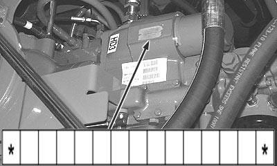
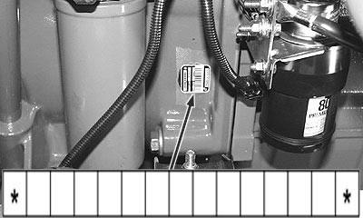
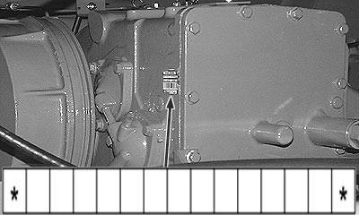
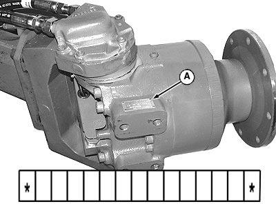
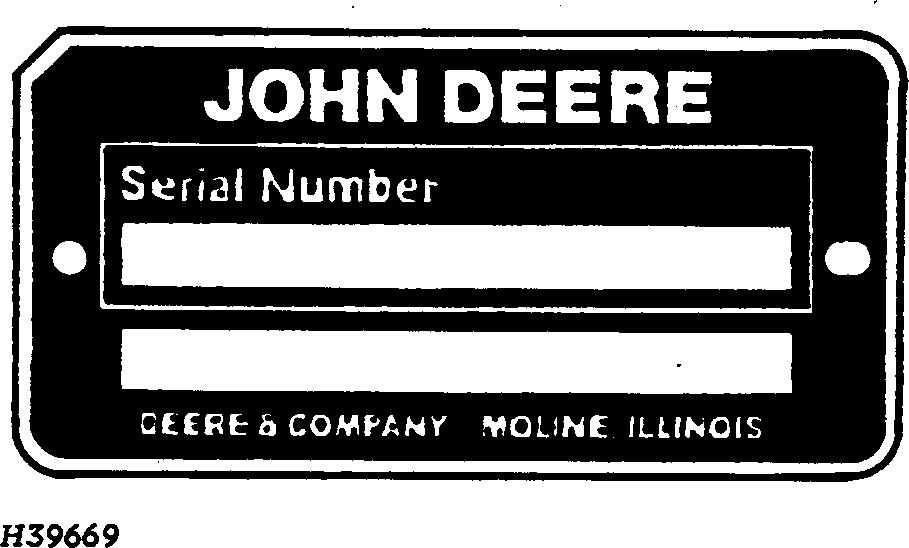
Identification Plates
Each combine has identification plates similar to the one shown. The letters and numbers stamped on these plates identify a component or assembly. ALL of these characters are needed when ordering parts or identifying a combine or component for any John Deere product support program. Also, they are needed for law enforcement to trace your combine if it is ever stolen.
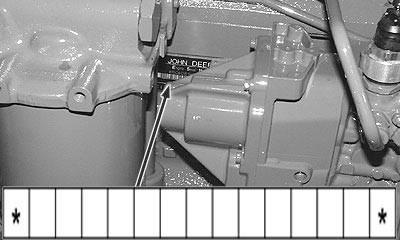
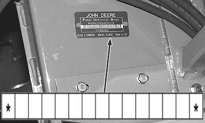
Combine Identification Number
Engine Serial Number
Hydrostatic Drive Unit Pump