
670,770,790,870,970,1070
Introduction
FOREWORD
This manual is written for an experienced technician. Essential tools required in performing certain service work are identified in this manual and are recommended for use.
Live with safety: Read the safety messages in the introduction of this manual and the cautions presented throughout the text of the manual.
NThis is the safety-alert symbol. When you see this symbol on the machine or in this manual, be alert to the potential for personal injury.
Technical manuals are divided in two parts: repair and diagnostics. Repair sections tell how to repair the components. Diagnostic sections help you identify the majority of routine failures quickly.
Information is organized in groups for the various components requiring service instruction. At the beginning of each group are summary listings of all applicable essential tools, service equipment and tools, other materials needed to do the job, service parts kits, specifications, wear tolerances, and torque values.
Binders, binder labels, and tab sets can be ordered by John Deere dealers direct from the John Deere Distribution Service Center.
This manual is part of a total product support program.
FOS MANUALS—REFERENCE
TECHNICAL MANUALS—MACHINE SERVICE
COMPONENT MANUALS—COMPONENT SERVICE
Fundamentals of Service (FOS) Manuals cover basic theory of operation, fundamentals of troubleshooting, general maintenance, and basic type of failures and their causes. FOS Manuals are for training new personnel and for reference by experienced technicians.
Technical Manuals are concise guides for specific machines. Technical manuals are on-the-job guides containing only the vital information needed for diagnosis, analysis, testing, and repair.
Component Technical Manuals are concise service guides for specific components. Component technical manuals are written as stand-alone manuals covering multiple machine applications.
Contents
SECTION10—GENERALINFORMATION Group05—Safety Group10—GeneralSpecifications Group15—RepairSpecifications Group20—FuelandLubricants Group25—SerialNumberLocations
SECTION20—ENGINEREPAIR Group05—670/770 Group06—870/970/1070 Group07—790 Group10—CoolingSystem Group15—ThrottleandGovernorControlLinkage Group20—FuelSystem
SECTION40—ELECTRICALSYSTEM Group05—Alternator Group10—Starter Group15—Sender,SwitchesandGauges
SECTION50—POWERTRAINREPAIR—670/770/790 Group05—ClutchHousing Group06—SingleStageClutch Group07—DualStageClutch Group10—Transmission Group15—RearPTODriveShaft Group20—Differential Group25—FinalDrive Group30—MechanicalFrontWheelDrive Group35—ThrottleandGovernorControlLinkage
Section55—POWERTRAINREPAIR —870/970/1070 Group05—ClutchHousing Group06—DualStageClutch Group10—Transmission Group15—RearPTODriveShaft Group20—Differential Group25—FinalDrive Group30—MechanicalFrontWheelDrive—870 Group35—MechanicalFrontWheelDrive —970/1070 Group40—MidMountPTO
SECTION60—STEERINGANDBRAKEREPAIR Group05—ManualSteering Group10—PowerSteering Group15—BrakeRepair—670/770/790 Group20—BrakeRepair—870/970/1070
SECTION70—HYDRAULICREPAIR Group05—HydraulicPumpandFilter Group10—Rockshaft—670/770/790 Group11—Rockshaft—870/970/1070 Group15—SelectiveControlValve Group20—RearAuxiliaryHydraulicLines
SECTION80—MISCELLANEOUSREPAIR Group05—Wheels Group10—FrontAxle Group15—Hood Group20—3-PointHitch Group25—SeatandSupport Group30—Roll-Gard Group35—MowerSpindles Group40—MowerGearbox
SECTION210—OPERATIONALCHECKOUT PROCEDUREANDSPECIFICATIONS Group05—TestandAdjustmentSpecifications Group10—OperationalCheckoutProcedures
SECTION220—ENGINEOPERATION,TESTS,AND ADJUSTMENTS
Group05—ComponentLocations Group10—TheoryofOperation Group15—EngineSystemDiagnosis
SECTION240—ELECTRICALSYSTEMOPERATION ANDTESTS
Group05—ComponentLocation Group10—TheoryofOperation Group15—DiagnosisandTest Group20—Schematic
Continuedonnextpage
Allinformation,illustrationsandspecificationsinthismanualarebasedon thelatestinformationavailableatthetimeofpublication.Therightis reservedtomakechangesatanytimewithoutnotice. TM1470-19-15JAN99
COPYRIGHT©1999 DEERE&COMPANY Moline,Illinois Allrightsreserved AJohnDeereILLUSTRUCTION™Manual
SECTION250—POWERTRAIN—670/770/790 Group05—ComponentLocation Group10—TheoryofOperation Group15—DiagnosisandTest
SECTION255—POWERTRAIN—870/970/1070
Group05—ComponentLocation Group10—TheoryofOperation Group15—DiagnosisandTest
SECTION260—STEERINGANDBRAKES Group05—ComponentLocation Group10—TheoryofOperation Group15—DiagnosisandTest
SECTION270—HYDRAULICSYSTEM Group05—ComponentLocation Group10—TheoryofOperation Group15—DiagnosisandTest Group20—Schematic
Group05—Safety ....................10-05-1
Group10—GeneralSpecifications
MachineSpecifications
670/770/790........................10-10-1
870/970/1070.......................10-10-4
Group15—RepairSpecifications
RepairSpecifications..................10-15-1
MetricSeriesTorqueChart............10-15-10
InchSeriesTorqueChart..............10-15-11
Group20—FuelandLubricants
FuelSpecifications....................10-20-1
FuelStorage.........................10-20-1
FillingtheFuelTank...................10-20-2
DieselEngineOil.....................10-20-3
EngineCoolant.......................10-20-4
Anti-ChatterTransmission/HydraulicOil....10-20-4
LubricantStorage.....................10-20-6
Group25—SerialNumberLocations ....10-25-1
RECOGNIZE SAFETY INFORMATION
This is the safety-alert symbol. When you see this symbol on your machine or in this manual, be alert to the potential for personal injury.
Follow recommended precautions and safe operating practices.

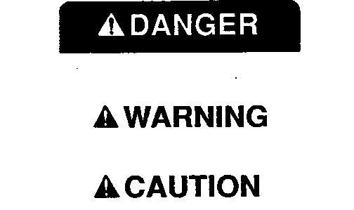
UNDERSTAND SIGNAL WORDS
A signal word—DANGER, WARNING, or CAUTION—is used with the safety-alert symbol. DANGER identifies the most serious hazards.
Safety signs with signal word DANGER or WARNING are typically near specific hazards.
General precautions are listed on CAUTION safety signs. CAUTION also calls attention to safety messages in this manual.
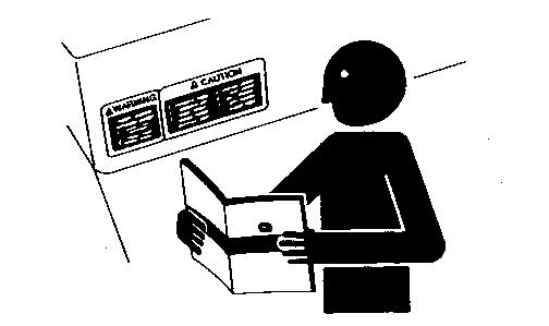
FOLLOW SAFETY INSTRUCTIONS
Carefully read all safety messages in this manual and on your machine safety signs. Keep safety signs in good condition. Replace missing or damaged safety signs.
Learn how to operate the machine and how to use controls properly. Do not let anyone operate without instruction.
Keep your machine in proper working condition. Unauthorized modifications to the machine may impair the function and/or safety and affect machine life.
HANDLE FLUIDS SAFELY—AVOID FIRES
When you work around fuel, do not smoke or work near heaters or other fire hazards.
Store flammable fluids away from fire hazards. Do not incinerate or puncture pressurized containers.
Make sure machine is clean of trash, grease, and debris.
Do not store oily rags; they can ignite and burn spontaneously.

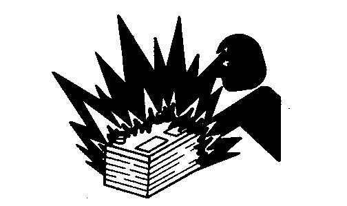
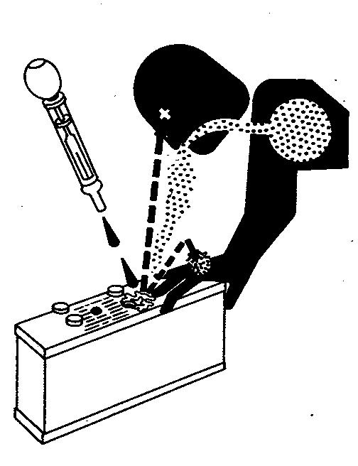
PREVENT BATTERY EXPLOSIONS
Keep sparks, lighted matches, and open flame away from the top of battery. Battery gas can explode.
Never check battery charge by placing a metal object across the posts. Use a volt-meter or hydrometer.
Do not charge a frozen battery; it may explode. Warm battery to 16˚C (60˚F).
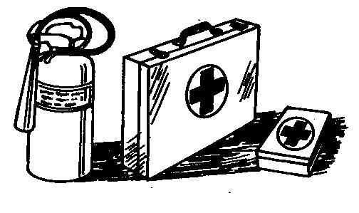
PREPARE FOR EMERGENCIES
Be prepared if a fire starts.
Keep a first aid kit and fire extinguisher handy.
Keep emergency numbers for doctors, ambulance service, hospital, and fire department near your telephone.
PREVENT ACID BURNS
Sulfuric acid in battery electrolyte is poisonous. It is strong enough to burn skin, eat holes in clothing, and cause blindness if splashed into eyes.
Avoid the hazard by:
1. Filling batteries in a well-ventilated area.
2. Wearing eye protection and rubber gloves.
3. Avoiding breathing fumes when electrolyte is added.
4. Avoiding spilling or dripping electrolyte.
5. Use proper jump start procedure.
If you spill acid on yourself:
1. Flush your skin with water.
2. Apply baking soda or lime to help neutralize the acid.
3. Flush your eyes with water for 10—15 minutes. Get medical attention immediately.
If acid is swallowed:
1. Drink large amounts of water or milk.
2. Then drink milk of magnesia, beaten eggs, or vegetable oil.
3. Get medical attention immediately.
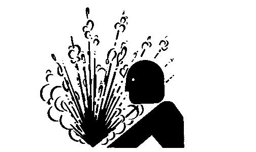
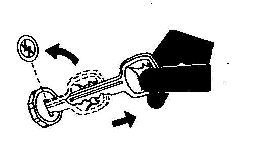
SERVICE COOLING SYSTEM SAFELY
Explosive release of fluids from pressurized cooling system can cause serious burns.
Shut off engine. Only remove filler cap when cool enough to touch with bare hands. Slowly loosen cap to first stop to relieve pressure before removing completely.
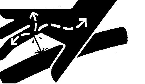
AVOID HIGH-PRESSURE FLUIDS
Escaping fluid under pressure can penetrate the skin causing serious injury.
Avoid the hazard by relieving pressure before disconnecting hydraulic or other lines. Tighten all connections before applying pressure.
Search for leaks with a piece of cardboard. Protect hands and body from high pressure fluids.
If an accident occurs, see a doctor immediately. Any fluid injected into the skin must be surgically removed within a few hours or gangrene may result. Doctors unfamiliar with this type of injury may call the Deere & Company Medical Department in Moline, Illinois, or other knowledgeable medical source.
PARK MACHINE SAFELY
Before working on the machine:
• Lower all equipment to the ground.
• Stop the engine and remove the key.
• Disconnect the battery ground strap.
• Hang a “DO NOT OPERATE” tag in operator station.
Group05–Engine–670/770
EngineRepair–UseCTM-3.............20-05-1
OtherMaterials......................20-05-1
RemoveandInstallEngine.............20-05-2
Group06–Engine–870/970/1070
EngineRepair–UseCTM-3.............20-06-1
OtherMaterials......................20-06-1
RemoveandInstallEngine.............20-06-2
Group07–Engine–790
Specifications
GeneralSpecifications................20-07-1
RepairSpecifications.................20-07-1
TestsandAdjustmentSpecifications.....20-07-4
OperationalTests.....................20-07-4
TorqueValues,Non-Standard Fasteners..........................20-07-4
SpecialTools........................20-07-5
OtherMaterials......................20-07-5
RemoveandInstallEngine.............20-07-7
EngineRepair......................20-07-14
RockerCoverRemoval/Installation.....20-07-14
RockerArmAssembly...............20-07-14
RockerArmComponents............20-07-15
CylinderHeadAndValves
RemovalAndInstallation.............20-07-17
CylinderHeadAndValves
DisassemblyAndAssembly..........20-07-18
ValveSeats.......................20-07-19
IntakeandExhaustValves...........20-07-20
ValveRecession...................20-07-21
ValveGuides......................20-07-21
ValveSprings......................20-07-22
ExhaustManifold...................20-07-23
IntakeManifold....................20-07-23
GrindValveSeats..................20-07-23
LapValves........................20-07-24
MeasurePiston-to-Cylinder
HeadClearance....................20-07-24
PistonandConnectingRod...........20-07-25
ConnectingRodBearing.............20-07-29
PistonRingGroove.................20-07-29
PistonRingEndGap................20-07-30
Section20
PistonPin........................20-07-30
PistonPinBore....................20-07-31
PistonPinBushing.................20-07-31
PistonDiameter...................20-07-32
CylinderBore.....................20-07-32 Deglazing........................20-07-33
Reboring.........................20-07-33
CrankshaftRearOilSeal............20-07-34
StartingMotorRemovalandInstallation20-07-52
StartingMotorDisassembly andAssembly.....................20-07-53
StartingMotorInspection/Test........20-07-56
StartingMotorGearTrain............20-07-58
StartingMotorSolenoid.............20-07-60
AlternatorRemovalAndInstallation....20-07-61
AlternatorDisassembly.............20-07-62
AlternatorComponents.............20-07-65
Group10–CoolingSystem
Radiator
670/770/790/870/970/1070
Remove,InspectandInstall...........20-10-1
Group15–ThrottleandGovernor ControlLinkage
ThrottleControlLinkage
670/770/790/870/970/1070
InspectandRepair..................20-15-1
Group20–FuelSystem
InjectionPump,Nozzle,andGovernorRepair–770/870/970/1070–UseCTM-3........20-20-1
FuelInjectionPump—790.............20-20-1
FuelInjectionNozzles—790............20-20-3
Remove,Inspect,andInstallFuelTank 670/770/790........................20-20-6
870/970/1070.......................20-20-7
Replace FuelSupplyPump..................20-20-3
FuelShut-OffSolenoid...............20-20-3
IntakeAirHeater–770/790/870/970/107020-20-4
YANMAR ENGINE REPAIR—USE CTM-3
For complete repair information the component technical manual (CTM) is also required.
Use the component manual in conjunction with this machine manual.
OTHER MATERIAL
Number
T43512
Name
Thread Lock and Sealer (Medium
Use
Apply to threads of front frame Strength) mounting cap screws.
REMOVE ENGINE
1. Remove fuel tank. (See procedure in Group 20.)
2. Remove starter. (See procedure in Section 40, Group 10.)
3. MFWD: Remove drive shaft. (See procedure in Section 50, Group 30.)
4. Remove fuel shut-off solenoid. (See procedure in Group 20.)
NCAUTION: Explosive release of fluids from pressurized cooling system can cause serious burns.
Shut off engine. Only remove filler cap when cool enough to touch with bare hands. Slowly loosen cap to first stop to relieve pressure before removing completely.
NOTE: Approximate coolant capacity is:
670.........................3.8 L (4.0 qt)
770.........................4.8 L (5.1 qt)
5. Drain coolant.
6. Remove radiator and air cleaner hoses. Close all openings using caps and plugs.
NCAUTION: Muffler may be hot. Allow muffler to cool before removing.
7. Remove muffler and gasket.
NCAUTION: Escaping fluid under pressure can penetrate the skin causing serious injury. Avoid the hazard by relieving pressure before disconnecting hydraulic or other lines. Tighten all connections before applying pressure. Search for leaks with a piece of cardboard. Protect hands and body from high pressure fluids.
If an accident occurs, see a doctor immediately. Any fluid injected into the skin must be surgically removed within a few hours or gangrene may result. Doctors unfamiliar with this type of injury may call the Deere & Company Medical Department in Moline, Illinois, or other knowledgeable medical source.
8. Lower rockshaft arms.
9. Manual steering: Disconnect drag link (E).
10. Remove line clamp cap screws (D).
11. Disconnect hose (B) and flange (F). Close all openings with caps and plugs.
12. Power steering: Remove hydraulic lines. (See procedure in Section 60, Group 10.)
13. Disconnect wiring connectors (C and G).
14. Disconnect cable (A).
A—Hour Meter Cable
B—Pressure Line Hose
C—Fusible Link Connector
D—Cap Screws (2 used)
E—Drag Link
F—Supply Line Mounting Flange
G—Alternator Wiring Connector
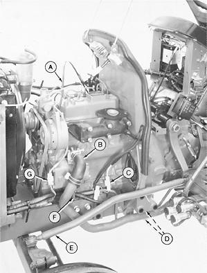
Left-Hand Side Shown
15. Close shutoff valve on fuel filter.
16. Disconnect lines (F and H). Close all openings using caps and plugs.
17. Disconnect wiring harness (C and G).
18. Disconnect wiring leads (D and J).
19. Remove support rod (E).
20. Remove control rod (I).
21. Remove air shield (B).
22. Remove bracket (A).
A—Fuel Tank Support Bracket
B—Air Shield
C—Wiring Harness
D—Coolant Temperature Switch Wiring Lead
E—Radiator Support Rod
F—Return Fuel Leak-Off Line
G—Wiring Harness
H—Fuel Pump Supply Line
I—Throttle Control Rod
J—Engine Oil Pressure Switch Wiring Lead
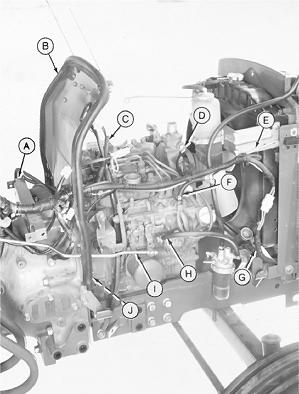
Right-Hand Side Shown
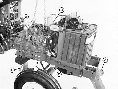
A—Lifting Brackets (2 used) C—Floor Jack E—Cap Screw (12 used) F—Support Stand B—Recovery Tank Assembly D—Wood Block (2 used)
23. Remove recovery tank assembly (B).
24. Remove rocker arm cover.
25. Install lifting brackets such as JDG19 or JT01748 Lifting Brackets (A).
26. Attach a hoist to engine.
27. Install support stand (F) under clutch housing.
28. Install a floor jack (C) under front weight support.
29. Install a wood block (D) between front axle and frame on both sides.
30. Remove six cap screws (E) from each side of frame.
31. Roll front end away from tractor.
NOTE: Put transmission in neutral to ease clutch shaft alignment with engine during installation.
32. Put transmission shift lever in neutral.
33. Remove eight cap screws and lock washers. Remove engine.
34. Make repairs as necessary. (See CTM-3.)
INSTALL ENGINE
1. Put transmission shift lever in neutral to ease clutch shaft alignment with engine.
2. Apply multipurpose grease to end of clutch shaft.
NOTE: Turn flywheel when installing engine, to engage engine with clutch shaft(s).
3. Install engine. Tighten cap screws to 54 N·m (40 lb-ft).
A—Lifting Brackets (2 used) C—Floor Jack
E—Cap Screw (12 used) F—Support Stand B—Recovery Tank Assembly D—Wood Block (2 used)
4. Apply thread lock and sealer (medium strength) to threads of cap screws (E).
5. Install front end to tractor. Tighten cap screws (E) to 90 N·m (65 lb-ft).
6. Remove wood blocks (D), floor jack (C) and support stand (F).
7. Remove lifting brackets (A).
8. Install rocker arm cover.
9. Install recovery tank assembly (B).

Engine—670/770/Remove and Install Engine
10. Install bracket (A).
11. Install air shield (B).
12. Install control rod (I).
13. Install support rod (E).
14. Connect wiring leads (D and J).
15. Connect wiring harness (C and G).
16. Connect lines (F and H).
17. Open shutoff valve on fuel filter.
A—Fuel Tank Support Bracket
B—Air Shield
C—Wiring Harness
D—Coolant Temperature Switch Wiring Lead
E—Radiator Support Rod
F—Return Fuel Leak-Off Line
G—Wiring Harness
H—Fuel Pump Supply Line
I—Throttle Control Rod
J—Engine Oil Pressure Switch Wiring Lead
Right-Hand Side Shown
18. Connect cable (A).
19. Connect wiring connectors (C and G).
20. Power steering: Install hydraulic lines. (See procedure in Section 60, Group 10.)
21. Connect flange (F) and hose (B).
22. Install line clamp cap screws (D).
23. Manual steering: Connect drag link (E).
24. Install muffler and new gasket.
25. Install radiator and air cleaner hoses.
26. MFWD: Install drive shaft. (See procedure in Section 50, Group 30.)
27. Install starter. (See procedure in Section 40, Group 10.)
28. Install fuel shut-off solenoid. (See procedure in Group 20.)
29. Install fuel tank. (See procedure in Group 20.) Left-Hand Side Shown
30. Fill radiator with proper coolant to top of filler neck. (See Engine Coolant in Section 10, Group 20.)
31. Adjust throttle control linkage. (See Section 220,
A—Hour Meter Cable
B—Pressure Line Hose
C—Fusible Link Connector
D—Cap Screws (2 used) Group 15.)
E—Drag Link
F—Supply Line Mounting Flange
G—Alternator Wiring Connector