644K 4WD Loader
Engine 6068HDW80 (T3), 6068HDW83 (S2)
Repair
( S . N . — 6 4 2 4 4 3 )
DOWNLOAD SERVICE REPAIR MANUAL
AIR
MANUAL 644K 4WD Loader Engine 6068HDW80 (T3), 6068HDW83 (S2) TM10695 27JUN19 (ENGLISH)
644K 4WD Loader
Engine 6068HDW80 (T3), 6068HDW83 (S2)
Repair
( S . N . — 6 4 2 4 4 3 )
AIR
MANUAL 644K 4WD Loader Engine 6068HDW80 (T3), 6068HDW83 (S2) TM10695 27JUN19 (ENGLISH)
This manual written for experienced Essential tools required performing certain service work are identified this manual and are recommended for use.
Live with safety: Read the safety messages the introduction this manual and the cautions presented throughout the text the

This the safety - alert symbol. When you see this symbol the machine this alert the potential for personal injury
T echnical manuals are divided two parts: repair and operation and Repair sections tell how repair the components. Operation and tests sections help you identify the majority routine failures quickly
Information organized groups for the various components requiring service the beginning each group are summary listings all applicable essential tools, service equipment and tools, other materials needed the job, service parts wear and torque
T echnical Manuals are concise guides for specific They are - the - job guides containing only the vital information needed for diagnosis, analysis, testing, and repair
Fundamental service information available from other sources covering basic theory fundamentals general and basic type failures and their causes.
IMPORT ANT : Use only supporting manuals designated for your specific incorrect manual improper service may occur . V erify product identification number (PIN) and engine model number when choosing the correct manual.
Choosing the Correct Supporting Manuals
John Deere four wheel drive (4WD) loaders are available dif ferent machine configurations based the various markets into which they are Dif ferent supporting manuals exist for dif ferent machine
When necessary , product serial numbers and engine model numbers are listed the front covers 4WD loader These numbers are used identify the correct supporting manual for your
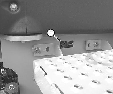
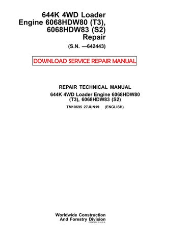
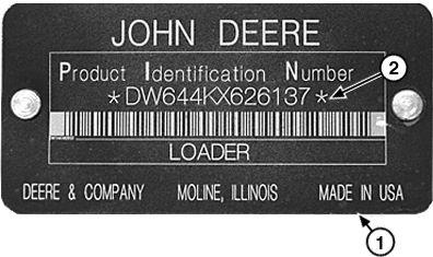
The product identification number (PIN) plate (1) located left side machine frame under the cab door Each machine has a - character PIN (2) - character PIN (3) shown this plate. The last 6 characters the PIN represent the product serial number
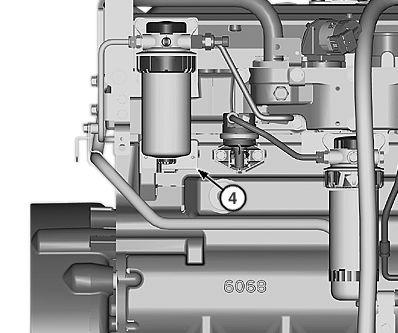
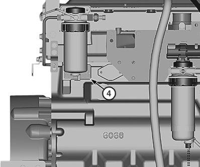
Engine Model Number Identification
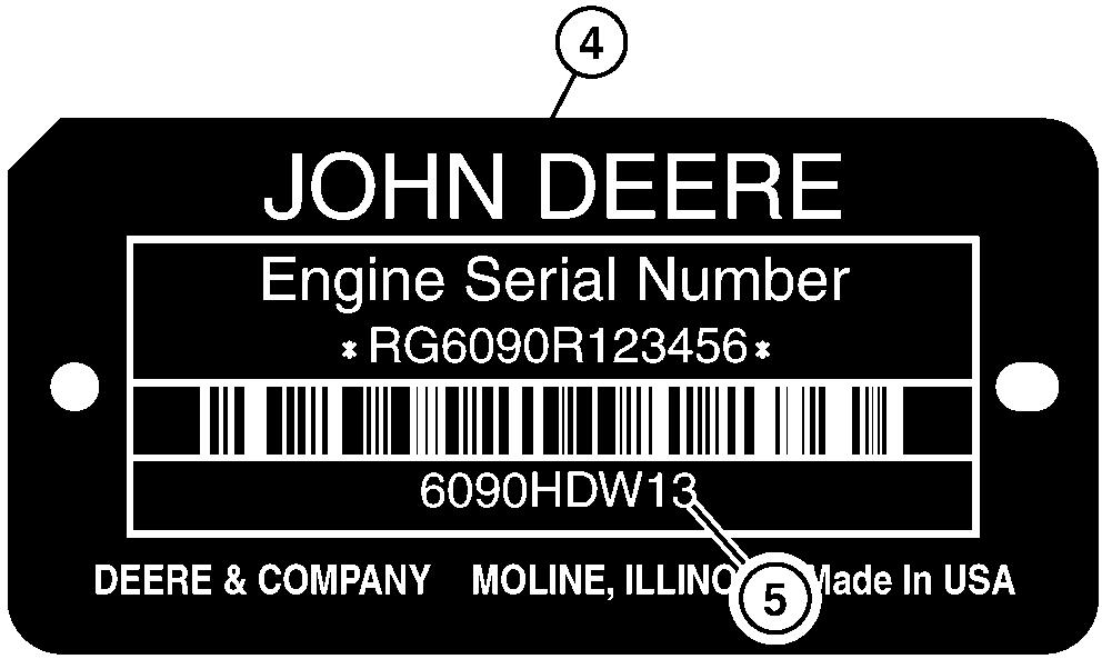
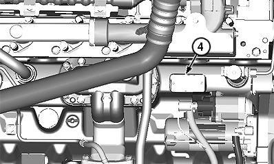
Plate
The engine serial number plate (4) located the right side the engine for engine model located the left side engine for engine models 6068HDW80 and Each engine has a 9 - character engine model number (5) shown this
Engine Emissions Level Identification
The 9 - character engine model number corresponds a specific engine emissions
Engine Model Number
Engine Emissions Level
6090HDW13 Interim T ier 4/Stage III B
6068HDW80 T ier 3/Stage III A
6068HDW83 Stage
For machines equipped with a - character where the 1 1 t h character “E”, “D”, “C”, this character also corresponds a specific engine emissions
NOTE: Later machines with a - character PIN identify engine emissions level (“E”, “D”, “C”) with the 1 1 t h character Earlier machines with a - character PIN not identify engine emissions level with the 1 1 t h character
- Character PIN 1 t h character)
Engine Emissions Level
xxxxxxxxxx E xxxxxx Interim T ier 4/Stage III B
xxxxxxxxxx D xxxxxx T ier 3/Stage III A
xxxxxxxxxx C xxxxxx Stage
Section Information
Group 0001 Information
Group 0003 orque V alues
Section Group Wheels and Fasteners
Section and Suspension Systems
Group 0200 and Installation
Group 0225 Shafts and U - Joints
Group 0250 Reduction Gears
Group 0260 System
Section 03—T ransmission
Group 0300 and Installation
Group 0350 —Gears, Bearings and Power Shift Clutch
Group 0360 System
Section Group 0400 and Installation
Section Auxiliary Systems
Group 0505 W eather Starting Aids
Group 0510 System
Group 0520 System
Group 0530 Exhaust System
Group 0560 Fuel Supply Systems
Section 07—Dampener Drive
Group 0752
Section 09—Steering System
Group 0960 System
Section 10—Service Brakes
Group 101 1 Elements
Group 1060 System
Section 1 Brake
Group 1 1 1 1 Elements
Group 1 160 System
Section Supporting Structure
Group 1740 Installation
Group 1746 Bottom Guards
Group 1749 W eights
Section ’ s Station
Group 1800 and Installation
Group 1810 Enclosure
Group 1821 and Seat Belt
Group 1830 and Air Conditioning
Section 19—Sheet Metal and Styling
Group 1910 Engine Enclosure
Section 31—Loader
Group 3102
Group 3140
Group 3160 System
Section Fabricated T ools
Group 9900 Fabricated T ools
Original All illustrations and specifications this manual are based the latest information available the time The right is reserved make changes any time without
Thanks very much for your reading,
Want to get more information,
Please click here, Then get the complete manual

NOTE:
If there is no response to click on the link above, please download the PDF document first, and then click on it.
When Operating Loader - 0001Keep Riders f Machine - 0001 -
Service Recommendations for 37° Flare and 30° Cone Seat Connectors . . . .
- 0003 - 4
Service Recommendations for O - Ring Boss Fittings - 0003 - 4
Service Recommendation O - Ring Boss Fittings Aluminum HousingExcavators - 0003 - 6
Service Recommendations for Flared T apered Threads
Service Recommendations for Flat
- 0003 - 7
Face O - Ring Seal Fittings - 0003 - 8
O - Ring Face Seal Fittings with SAE Inch Hex Nut and Stud End for High Pressure - 0003 - 9
O - Ring Face Seal Fittings with Metric Hex Nut and Stud End for Standard Pressure
- 0003 - 1 1
O - Ring Face Seal Fittings with Metric Hex Nut and Stud End for High Pressure - 0003 -
Service Recommendations for Metric Series Four Bolt Flange Fitting - 0003 -
Service Recommendations For Inch Series Four Bolt Flange Fittings - 0003Inch Series Four Bolt Flange For High Pressure - 0003 -
Service Recommendations
For Non - Restricted Banjo (Adjustable) Fittings - 0003 -
- 0001 - 1 1
A void Backover Accidents - 0001A void Machine T ip Over .
Slopes - 0001 - 1 1 Operating T raveling Public Roads - 0001Inspect and Maintain ROPS - 0001Add and Operate Attachments
- 0001Park And Prepare For Service Safely - 0001Service Cooling System Safely - 0001 -
Service T ires Safely - 0001Remove Paint Before W elding
Heating - 0001Make W elding Repairs Safely - 0001Drive Metal Pins Safely
0001Group 0003 orque V alues T
0003 - 2
- 0003 - 3
Service Recommendations For O - Ring Boss Fittings With Shoulder - 0003Metric O - Ring Seal DIN 20078 - 0003 -
This the safety alert symbol. When you see this symbol your machine this alert for the potential personal injury
Follow the precautions and safe operating practices highlighted this
A signal word DANGER, W ARNING, CAUTION is used with the safety alert DANGER identifies the most serious

your DANGER signs are red color , W ARNING signs are orange, and CAUTION signs are yellow . DANGER and W ARNING signs are located near specific General precautions are CAUTION

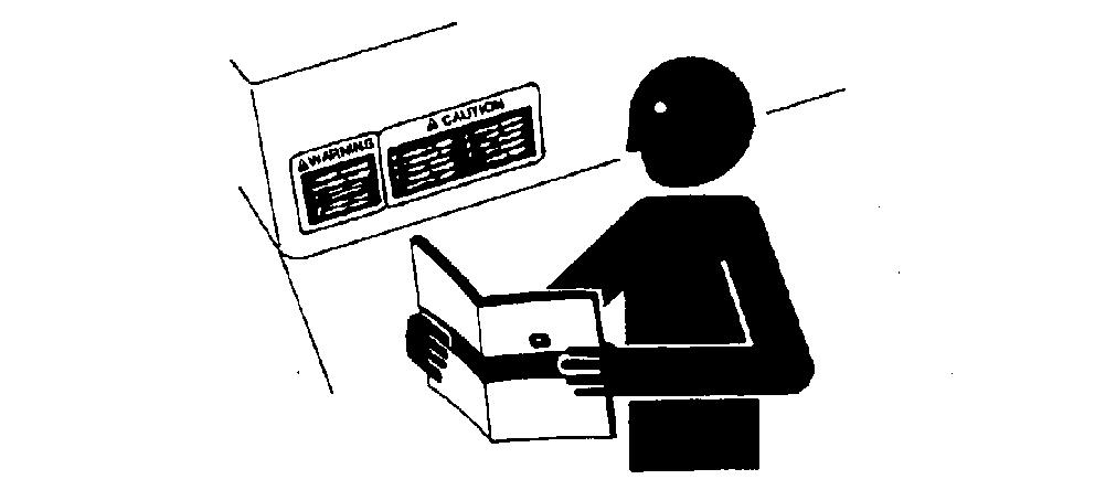
Read the safety messages in this manual and the machine. Follow these warnings and instructions carefully Review them frequently Keep safety signs good Replace missing damaged safety
Replacement safety signs are available from your authorized John Deere dealer
sure all operators this machine understand every safety Replace manual and safety labels immediately missing
not operate this machine unless you have read the manual carefully and you have been qualified supervised training and
Know and observe all safety rules that may apply your work situation and your work site.
Familiarize yourself with the job site and your surroundings before operating. T all controls and machine functions with the machine in open area before starting
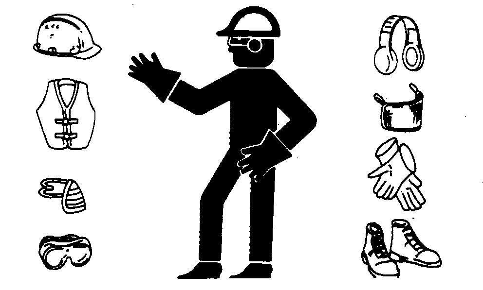
Guard against injury from flying pieces metal debris; wear goggles safety
W ear close fitting clothing and safety equipment appropriate the
Prolonged exposure loud noise can cause impairment loss hearing. W ear suitable hearing protection such earmuf earplugs protect against objectionable uncomfortable loud
John Deere recommends using only genuine John Deere replacement parts ensure machine performance. Never substitute genuine John Deere parts with alternate parts not intended for the application these can create hazardous situations hazardous Non - John Deere any damage failures resulting from their use, are not covered any John Deere warranty .
reliability , and may create a hazard for the operator others near the machine. The installer any modification which may fect the electronic controls this machine responsible for establishing that the modification does not adversely fect the machine its
Modifications this addition unapproved products may fect machine stability
Always contact authorized John Deere dealer before making machine modifications that change the intended balance the that alter machine reliability
Special work situations machine attachments may create environment with falling flying
Loading using fork operating in waste management applications requires special work Added cab guarding protect the operator may also
Use load - clamping grapples keep bulky loads from falling and add special screens guarding when objects may directed toward the Contact your authorized John Deere dealer for information devices intended protect the operator from falling flying objects special work situations.
Inspect machine carefully each day walking around before
Keep all guards and shields in good condition and properly Fix damage and replace worn broken parts immediately Pay special attention hydraulic hoses and electrical
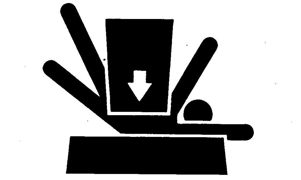
Entanglements in moving parts can cause serious injury
Stop engine before examining, adjusting maintaining any part machine with moving parts.
Keep guards and shields in Replace any guard shield that has been removed for access soon service repair
Inspect hydraulic hoses periodically – least once per year – for exposed wire braid any other signs wear
Replace worn damaged hose assemblies immediately with John Deere approved replacement
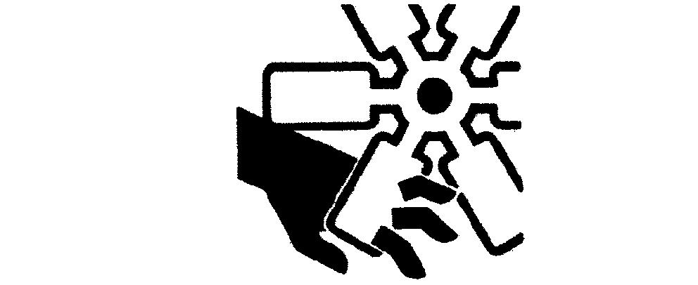
Escaping fluid under pressure can penetrate the skin causing serious injury
A void the hazard relieving pressure before disconnecting hydraulic other T ighten all connections before applying
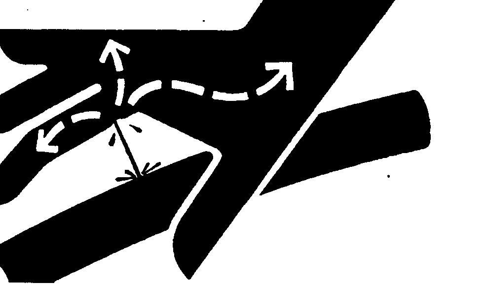
Search for leaks with a piece Protect hands and body from high - pressure accident occurs, see a doctor immediately . Any fluid injected into the skin must surgically removed within a few hours gangrene may Doctors unfamiliar
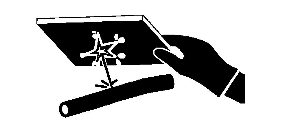
This machine uses a high - pressure hydraulic Escaping oil under pressure can penetrate the skin causing serious injury
Never search for leaks with your hands. Protect Use a piece cardboard find location escaping Stop engine and relieve pressure before disconnecting lines working hydraulic hydraulic oil penetrates your skin, see a doctor immediately . Injected oil must removed surgically within hours gangrene may result. Contact a knowledgeable medical source the Deere & Company Medical Department

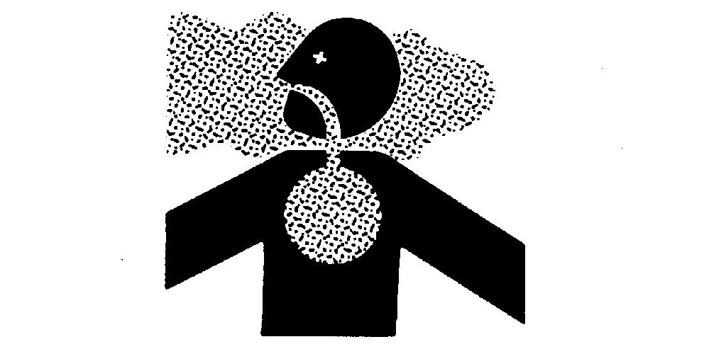
Prevent asphyxiation. Engine exhaust fumes can cause sickness
you must operate enclosed provide adequate Use exhaust pipe extension remove the exhaust fumes open doors and windows bring outside air into the
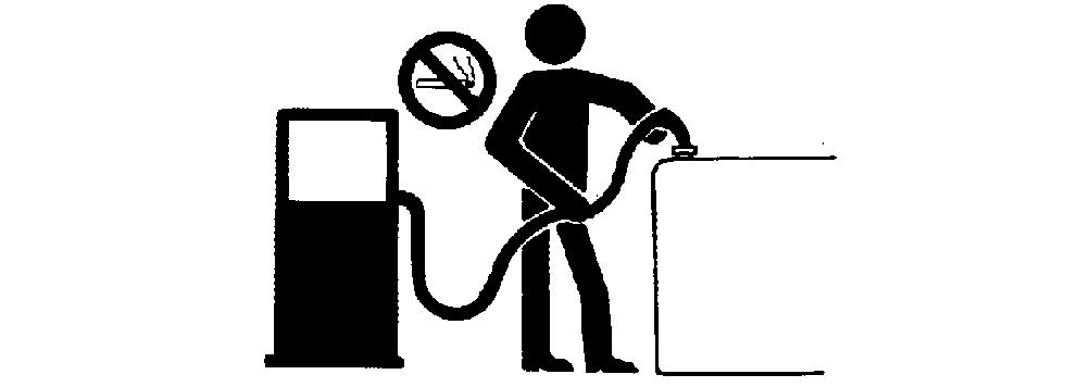
Handle Fuel Safely: Store flammable fluids away from fire Never refuel machine while smoking when near sparks
Clean Machine Regularly: Keep grease and oil from accumulating engine around fuel hydraulic exhaust and electrical Never store oily rags flammable materials inside a machine
Maintain Hoses and W iring: Replace hydraulic hoses immediately they begin and clean any oil
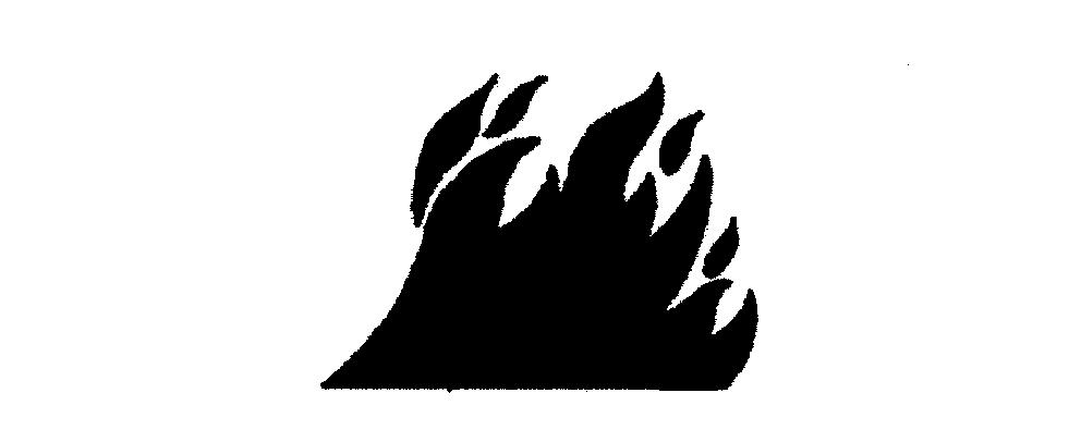
Examine electrical wiring and connectors frequently for
Keep A Fire Extinguisher A vailable: Always keep a multipurpose fire extinguisher near the Know how use extinguisher properly

Keep engine compartment, radiator , batteries, hydraulic exhaust fuel and station clean and free
Clean any oil spills fuel spills machine
T emperature engine compartment may immediately after engine is GUARD FOR FIRES DURING THIS
Open access door(s) cool the engine faster , and clean engine
Battery gas can Keep lighted and open flame away from the top battery
Never check battery charge placing a metal object across the Use a voltmeter hydrometer
not charge a frozen battery; it may W arm battery 16°C (60°F).
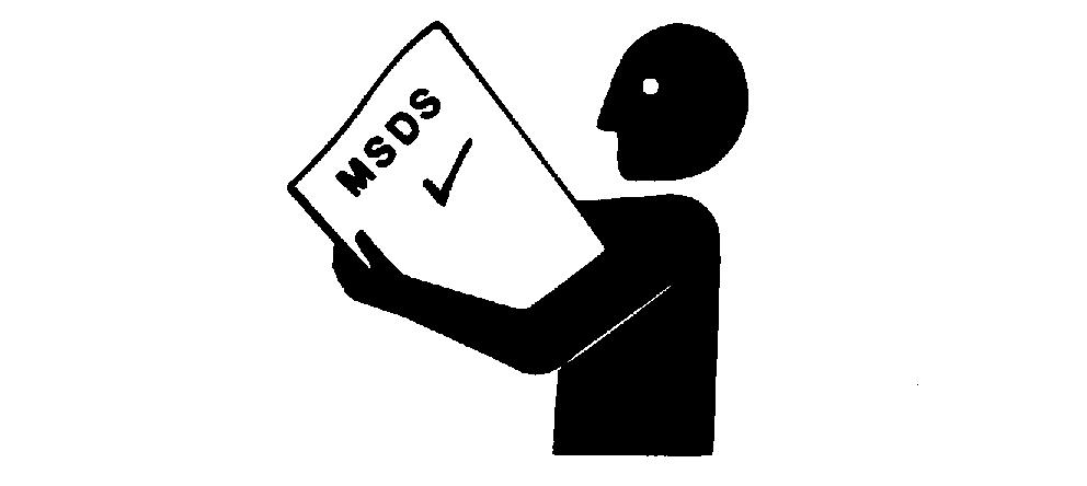
Exposure hazardous chemicals can cause serious injury Under certain paints and adhesives used with this machine may
uncertain about safe handling use these chemical contact your authorized dealer for a Material Safety Data Sheet (MSDS) internet website http://www The MSDS describes physical and health hazards, safe use procedures, and emergency response techniques for chemical substances. Follow MSDS recommendations handle chemical products safely
Improper disposal waste can threaten the Fuel, oils, coolants, filters and batteries used with this machine may harmful not disposed properly
Never pour waste onto the down a into any water
Air conditioning refrigerants can damage the Government regulations may require using a certified service center recover and recycle used
uncertain about the safe disposal contact your local environmental recycling center your dealer for more
prepared emergency occurs a fire
Keep a first aid kit and fire extinguisher handy .
Keep emergency numbers for ambulance and fire department near your
Prevent falls facing the machine when getting and Maintain 3 - point contact with steps and Never use machine controls
Use extra care when snow , moisture present slippery Keep steps clean and free grease Never jump when exiting Never mount dismount a moving
A void unexpected machine movement. Start engine only while sitting Ensure all controls and working tools are in proper position for a parked
Never attempt start engine from the not attempt start engine shorting across the starter solenoid

Use seat belt when operating machine . Remember fasten seat belt when loading and unloading from trucks and during other
Examine seat belt frequently sure webbing not cut torn. Replace seat belt immediately any part damaged does not function properly .
The complete seat belt assembly should replaced every 3 regardless
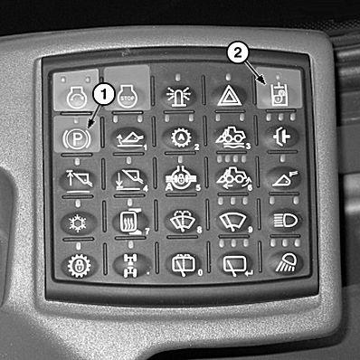
Lower all equipment the ground during work Place transmission control in press park brake switch (1) engage park press pilot enable/boom down switch (2) disable the hydraulics, and stop engine before allowing anyone approach the
Follow these same precautions before standing leaving the seat, exiting the
Park Brake Switch Pilot Enable/Boom Down Switch
A void contact with gas lines, buried cables, and water Call utility line location services identify all underground utilities before starting
Prepare work site properly . A void operating near structures objects that could fall onto the Clear away debris that could move unexpectedly run over
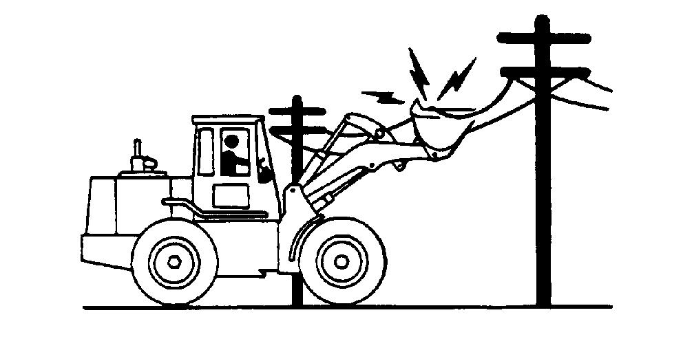
A void boom attachment contact with overhead obstacles overhead electrical lines. Never move machine closer than 3 m (10 plus twice the line insulator length overhead
Keep bystanders clear all times. Keep bystanders away from raised and unsupported
A void swinging raising loads over near Use barricades a signal person keep vehicles and pedestrians away Use a signal person moving machine congested areas where visibility is restricted. Always keep signal person view . Coordinate hand signals before starting machine.
Operate only solid footing with strength suf ficient support especially alert working near embankments
A void working under overhanging embankments stockpiles that could collapse under
Reduce machine speed when operating with tool near ground when obstacles may hidden during snow removal clearing high speeds hitting obstacles uneven manholes) can cause a sudden Always wear your seat
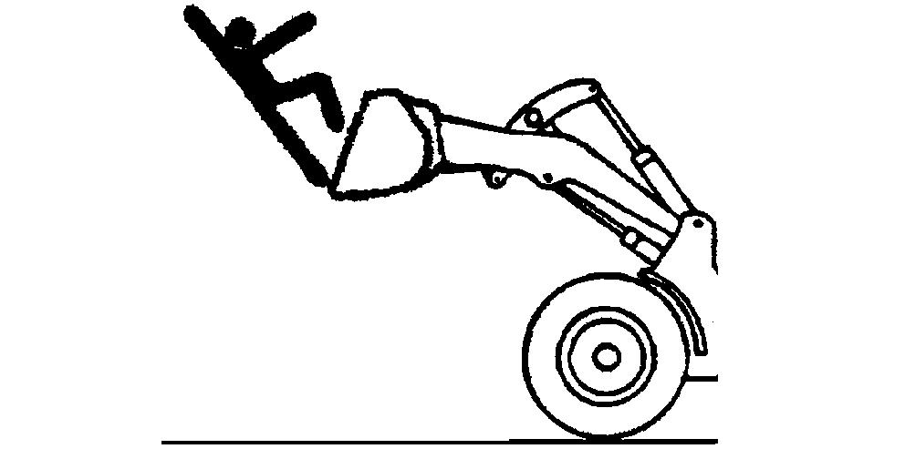
Never use the loader lift people. not allow anyone ride the bucket use the bucket a work
Operate carefully with raised loads. Raising the load reduces machine stability , especially side slopes unstable Drive and turn slowly with a raised
Ensure that objects the bucket are secure. not attempt lift carry objects that are too big too long fit inside the bucket unless secured with adequate chain other Keep bystanders away from raised
careful when lifting objects. Never attempt lift objects too heavy for your Assure machine stability and hydraulic capability with a test lift before attempting other Use adequate chain sling and proper rigging techniques attach and stabilize Never lift object above near another
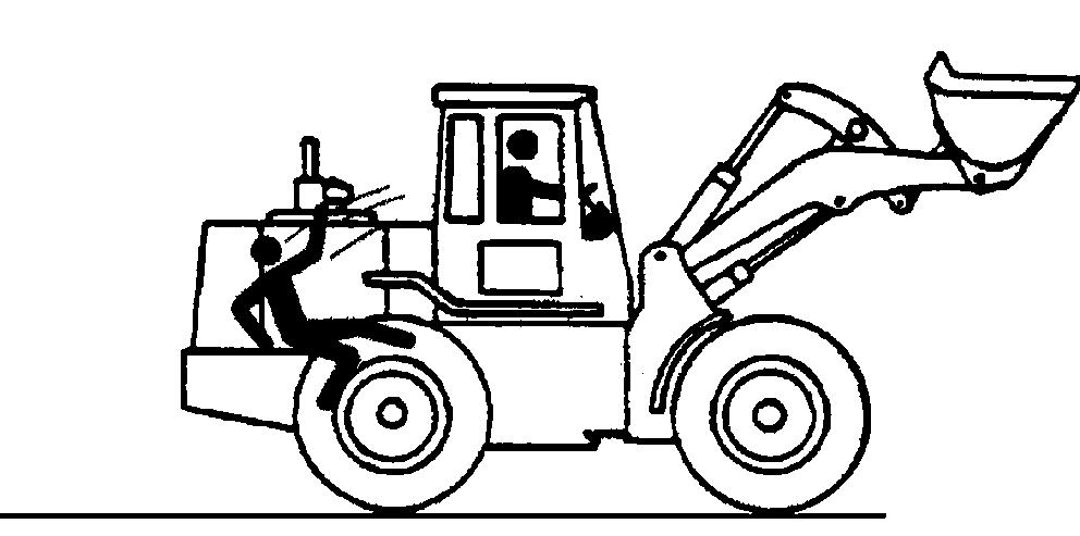
Only allow operator Riders are subject injury . They may fall from machine, caught between machine struck foreign
Riders may obstruct operator ’ s view impair his ability operate machine safely .
Before moving machine, sure that all persons are clear machine path. T urn around and look directly for best visibility Use mirrors assist checking all around Keep windows and mirrors and good repair
certain reverse warning alarm working properly .
Use a signal person when backing view obstructed when close Keep signal person view all Use prearranged hand signals
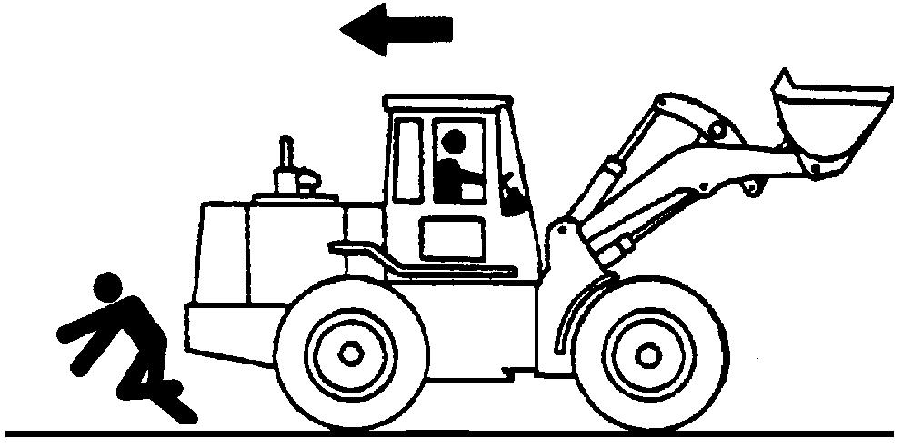
not rely the rear camera and radar object detection systems determine personnel are behind the
The system has limitations due maintenance practices, environmental conditions, and operating range.
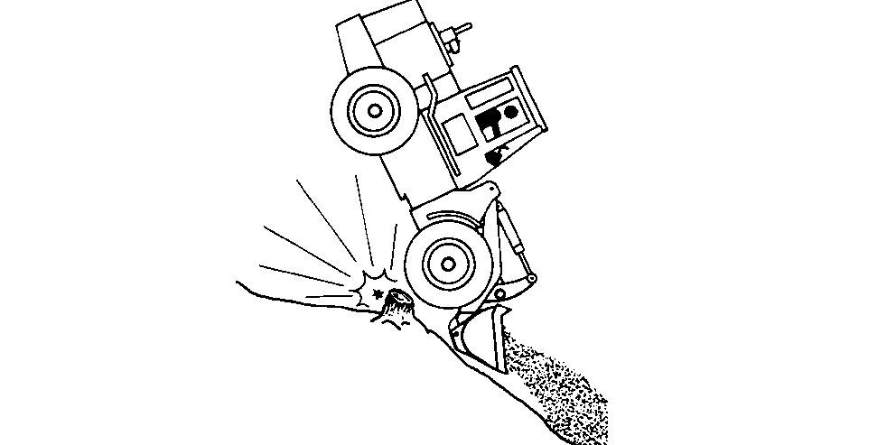
Use seat belt all times.
not jump the machine tips. Y will unlikely jump clear and the machine may crush
Load and unload from trucks trailers carefully sure truck wide enough and a firm level Use loading ramps and attach them properly truck bed.
careful slopes. A void sharp Balance loads weight evenly distributed and load Carry tools and loads close the ground aid visibility and lower center gravity . Use extra care soft, rocky , frozen ground.
Know the capacity the not careful with heavy Using oversize buckets lifting heavy objects reduces machine stability
Ensure solid footing. Use extra care in soft ground conditions that may not uniformly support the especially when raising the not operate close banks open excavations that may cave in and cause machine tip fall.
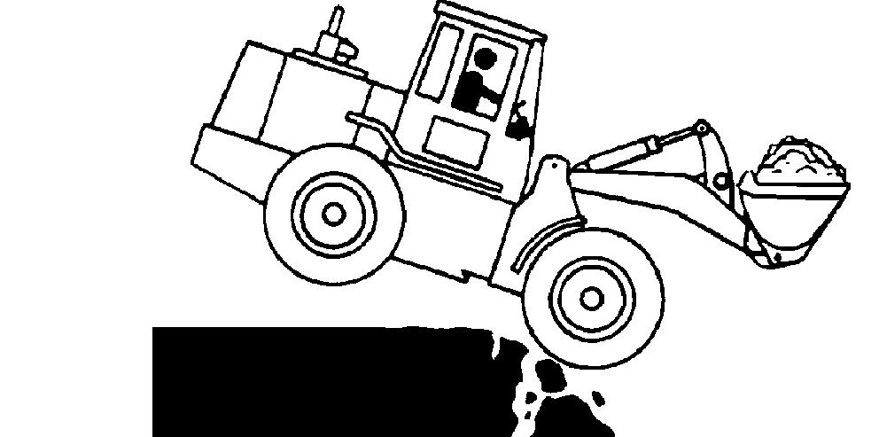
A void side slope travel whenever Drive steep slope forward and down
Select low gear speed before starting down The grade the slope will limited ground condition and load being
Use service brakes control
Sudden brake application with a loaded bucket downhill side could cause machine tip forward.
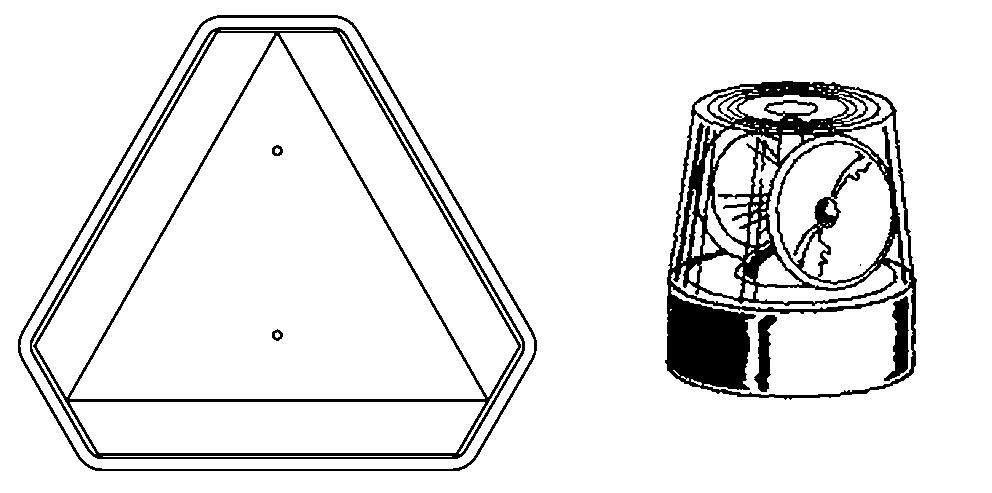
Machines that work near vehicle traf fic travel slower than normal highway speeds must have proper lighting and markings assure they are visible other
Install additional slow moving vehicle (SMV) other devices and use required make the machine visible and identify it a work Check state and local regulations assure Keep these devices clean and in working
A damaged roll - over protective structure (ROPS) should not
T o maintain the ROPS:
• Replace missing hardware using correct grade
The protection fered ROPS will impaired ROPS subjected structural is involved in overturn any way altered
• Check hardware
• Check isolation mounts for looseness wear; replace them necessary
ROPS was loosened removed for any inspect carefully before operating the machine
• Check ROPS for cracks physical
Always verify compatibility attachments contacting your authorized dealer Adding unapproved attachments may fect machine stability reliability , and may create a hazard for others near the
Ensure that a qualified person involved in attachment Add guards machine if operator protection required
V erify that all connections are secure and attachment responds properly
Carefully read attachment manual and follow all instructions and warnings. area free bystanders and obstructions, carefully operate attachment learn its characteristics and range
W arn others service work. Always park and prepare your machine for service repair properly
• Park machine a level surface and lower equipment the
• Engage park
• Stop
• Install frame locking bar
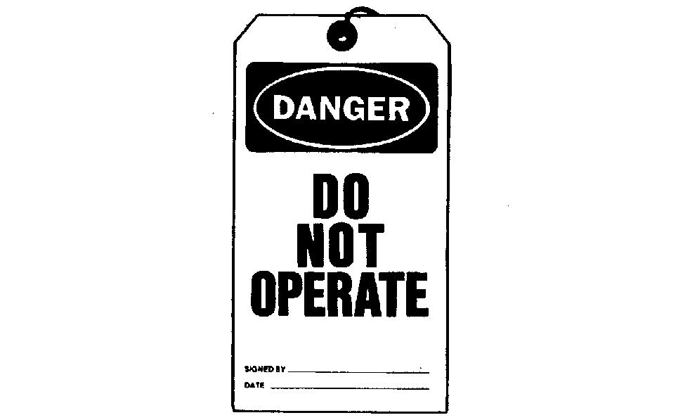
• Attach a NOT OPERA tag in obvious place the station.
Securely support machine attachment before working under
• not support machine with other hydraulically actuated
• not support machine with cinder blocks wooden pieces that can crumble
• not support machine with a single jack other devices that could slip out place.
Understand service procedures before beginning Keep service area clean and dry Use two people whenever the engine must running for service
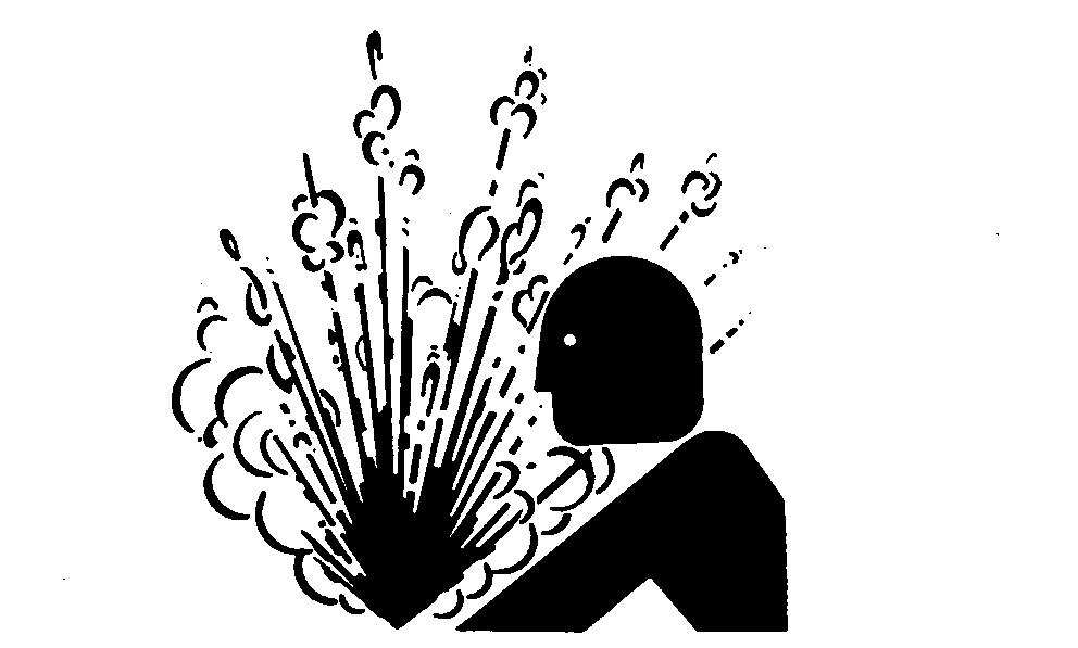
Explosive release fluids from pressurized cooling system can cause serious
not service radiator through the radiator cap. Only fill through the surge tank filler cap. Shut f engine. Only remove surge tank filler cap when cool enough touch with bare Slowly loosen cap relieve pressure before removing completely
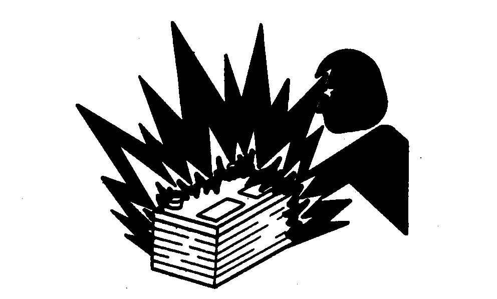
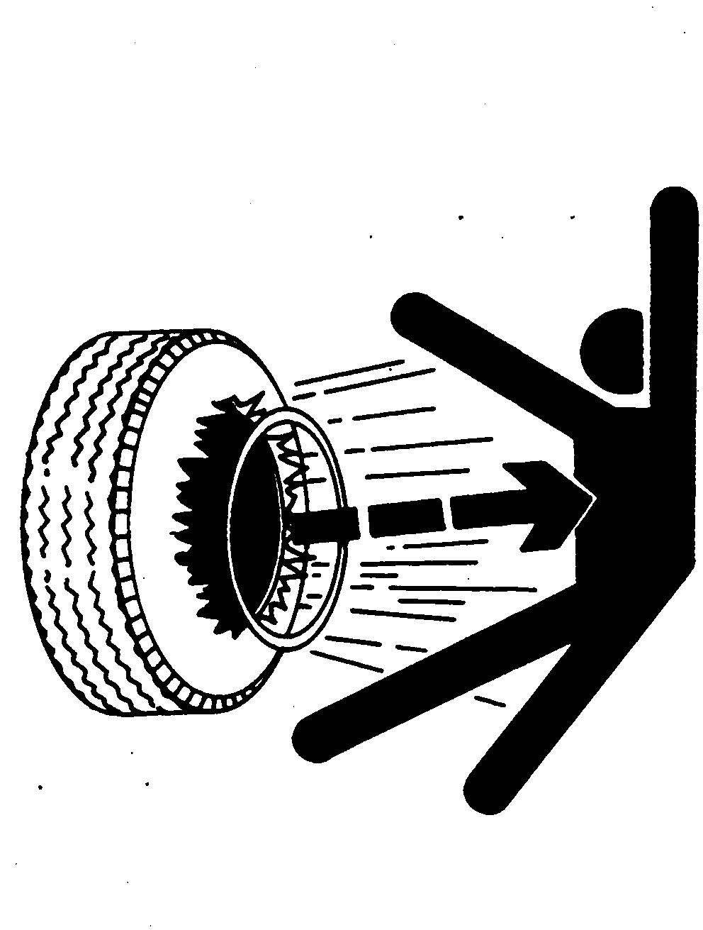
Explosive separation a tire and rim parts can cause serious injury
not attempt mount a tire unless you have the proper equipment and experience perform the
Always maintain the correct tire not inflate the tires above the recommended pressure. Never weld heat a wheel and tire assembly The heat can cause increase air pressure resulting in a tire W elding can structurally weaken deform the
When inflating tires, use a clip - chuck and extension hose long enough allow you stand one side and NOT front over the tire assembly Use a safety cage
Check wheels for low cuts, damaged rims missing lug bolts and nuts.
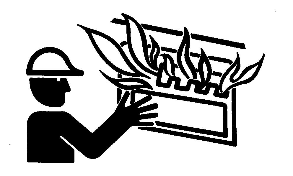
Remove Paint Before W elding Heating
A void potentially toxic fumes and dust.
Hazardous fumes can generated when paint is heated using a
Remove paint before heating:
• Remove paint a minimum 100 from area fected paint cannot wear approved respirator before heating welding.
• you sand grind paint, avoid breathing the dust. W ear approved respirator
• you use solvent paint stripper , remove stripper with soap and water before Remove solvent paint stripper containers and other flammable material from Allow fumes disperse least minutes before welding heating.
not use a chlorinated solvent areas where welding will take
all work area that well ventilated carry toxic fumes and dust away .
Dispose paint and solvent properly