Service & Repair Guide
John Deere 240 250 Skid Steer Fuel injection system Repair Manual

John Deere 240 250 Skid Steer Fuel injection system Repair Manual

John Deere 240 250 Skid Steer Fuel injection system Repair Manual
John Deere 240 250 Skid Steer Fuel injection system Repair Manual

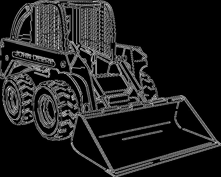

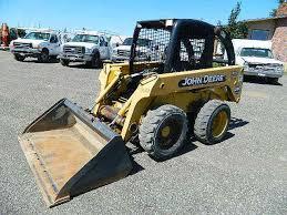
240 and 250 Skid Steer

This technical manual is written for an experienced technician and contains sections that are specifically for this product It is a part of a total product support program


The manual is organized so that all the information on a particular system is kept together The order of grouping is as follows:
• Table of Contents
• Specifications
• Theory of Operation
• Troubleshooting Diagram
• Diagnostics
• Tests & Adjustments
• Repair


Note: Depending on the particular secti system being covered, not all of the above g s may be used


Each section will be identified with a symb an a number The groups and pages within a ill be consecutively numbered

All information, illustrations and specifications in this manual are based on the latest information available at the time of publication. The right is reserved to make changes at any time without notice


We appreciate your input on this manual To help, there are postage paid post cards included at the back If you find any errors or want to comment on the layout of the manual please fill out one of the cards and mail it back to us

COPYRIGHT© 2000
JOHN DEERE COMMERICAL WORKSITE PRODUCTS
Knoxville, Tennessee
All rights reserved
Previous Editions
Copyright© 1999 Deere & Company


This is the safety-alert symbol When you see this symbol on your machine or in this manual, be alert to the potential for personal injury
Follow recommended precautions and safe servicing practices
A signal word DANGER, WARNING, or CAUTION is used with the safety-alert symbol DANGER identifies the most serious hazards.
DANGER or WARNING safety signs are located near specific hazards General precautions are listed on CAUTION safety signs. CAUTION also calls attention to safety messages in this manual


Replace missing or damaged safety signs See the machine operator’s manual for correct safety sign placement
When you work around fuel, do not smoke or work near heaters or other fire hazards
Store flammable fluids away from fire hazards Do not incinerate or puncture pressurized containers.
Make sure machine is clean of trash, grease, and debris
Do not store oily rags; they can ignite and burn spontaneously
Be prepared if a fire starts
Keep a first aid kit and fire extinguisher handy.
Keep emergency numbers for doctors, ambulance service, hospital, and fire department near your telephone.


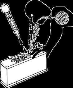
• Keep sparks, lighted matches, and open flame away from the top of battery. Battery gas can explode.
• Never check battery charge by placing a metal object across the posts Use a volt-meter or hydrometer
• Do not charge a frozen battery; it may explode. Warm battery to 16°C (60°F)
• Sulfuric acid in battery electrolyte is poisonous It is strong enough to burn skin, eat holes in clothing, and cause blindness if splashed into eyes
• Avoid acid burns by:
1. Filling batteries in a well-ventilated area.
2 Wearing eye protection and rubber gloves
3. Avoiding breathing fumes when electrolyte is added.
4 Avoiding spilling or dripping electrolyte
5.Using proper jump start procedure.
• If you spill acid on yourself:
1 Flush your skin with water
2 Apply baking soda or lime to help neutralize the acid
3 Flush your eyes with water for 10 15 minutes
4 Get medical attention immediately
• If acid is swallowed:
1.Drink large amounts of water or milk.
2 Then drink milk of magnesia, beaten eggs, or vegetable oil
3. Get medical attention immediately.
Escaping fluid under pressure can penetrate the skin causing serious injury
Avoid injury from escaping fluid under pressure by stopping the engine and relieving pressure in the system before disconnecting or connecting hydraulic or other lines Tighten all connections before applying pressure.
Search for leaks with a piece of cardboard Protect hands and body from high pressure fluids
If an accident occurs, see a doctor immediately Any fluid injected into the skin must be surgically removed within a few hours or gangrene may result Doctors unfamiliar with this type of injury should reference a knowledgeable medical source Such information is available from Deere & Company Medical Department in Moline, Illinois, U S A , (1-800-822-8262 U.S.A. or Canada).


Flammable spray can be generated by heating near pressurized fluid lines, resulting in severe burns to yourself and bystanders Do not heat by welding, soldering, or using a torch near pressurized fluid lines or other flammable materials Pressurized lines can be accidentally cut when heat goes beyond the immediate flame area


Wear close fitting clothing and safety equipment appropriate to the job
Prolonged exposure to loud noise can cause impairment or loss of hearing Wear a suitable hearing protective device such as earmuffs or earplugs to protect against objectionable or uncomfortable loud noises
Operating equipment safely requires the full attention of the operator Do not wear radio or music headphones while operating machine.
Tie long hair behind your head Do not wear a necktie, scarf, loose clothing, or necklace when you work near machine tools or moving parts If these items were to get caught, severe injury could result
Remove rings and other jewelry to prevent electrical shorts and entanglement in moving parts
Use tools appropriate to the work Makeshift tools and procedures can create safety hazards. Use power tools only to loosen threaded parts and fasteners For loosening and tightening hardware, use the correct size tools DO NOT use U S measurement tools on metric fasteners. Avoid bodily injury caused by slipping wrenches Use only service parts meeting John Deere specifications
Before working on the machine:
1 Lower all equipment to the ground
2. Relieve hydraulic pressure.
3 Stop the engine and remove the key
4 Disconnect the battery ground strap
5 Hang a “DO NOT OPERATE” tag in operator station


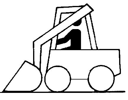
If you must work on a lifted machine or attachment, securely support the machine or attachment
Do not support the machine on cinder blocks, hollow tiles, or props that may crumble under continuous load Do not work under a machine that is supported solely by a jack Follow recommended procedures in this manual
Lifting heavy components incorrectly can cause severe injury or machine damage Follow recommended procedure for removal and installation of components in the manual
Before starting a job:
1 Clean work area and machine
2. Make sure you have all necessary tools to do your job.
3 Have the right parts on hand
4. Read all instructions thoroughly; do not attempt shortcuts.
Directing pressurized water at electronic/electrical components or connectors, bearings, hydraulic seals, fuel injection pumps or other sensitive parts and components may cause product malfunctions Reduce pressure and spray component at a 45 to 90 degree angle
Illuminate your work area adequately but safely Use a portable safety light for working inside or under the machine. Make sure the bulb is enclosed by a wire cage. The hot filament of an accidentally broken bulb can ignite spilled fuel or oil
Engine exhaust fumes can cause sickness or death If it is necessary to run an engine in an enclosed area, remove the exhaust fumes from the area with an exhaust duct system
If you do not have an exhaust duct system, open the doors and get outside air into the area.
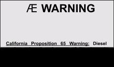
Diesel engine exhaust and some of its constituents are known to the State of California to cause cancer, birth defects, and other reproductive harm.
Avoid potentially toxic fumes and dust. Hazardous fumes can be generated when paint is heated by welding, soldering, or using a torch Do all work outside or in a well-ventilated area Dispose of paint and solvent properly. Remove paint before welding or heating If you sand or grind paint, avoid breathing the dust Wear an approved respirator If you use solvent or paint stripper, remove stripper with soap and water before welding. Remove solvent or paint stripper containers and other flammable material from area Allow fumes to disperse at least 15 minutes before welding or heating

Explosive separation of a tire and rim parts can cause serious injury or death.
Do not attempt to mount a tire unless you have the proper equipment and experience to perform the job. Always maintain the correct tire pressure Do not inflate the tires above the recommended pressure Never weld or heat a wheel and tire assembly The heat can cause an increase in air pressure resulting in a tire explosion Welding can structurally weaken or deform the wheel
When inflating tires, use a clip-on chuck and extension hose long enough to allow you to stand to one side and NOT in front of or over the tire assembly Use a safety cage if available.
Check wheels for low pressure, cuts, bubbles, damaged rims or missing lug bolts and nuts.
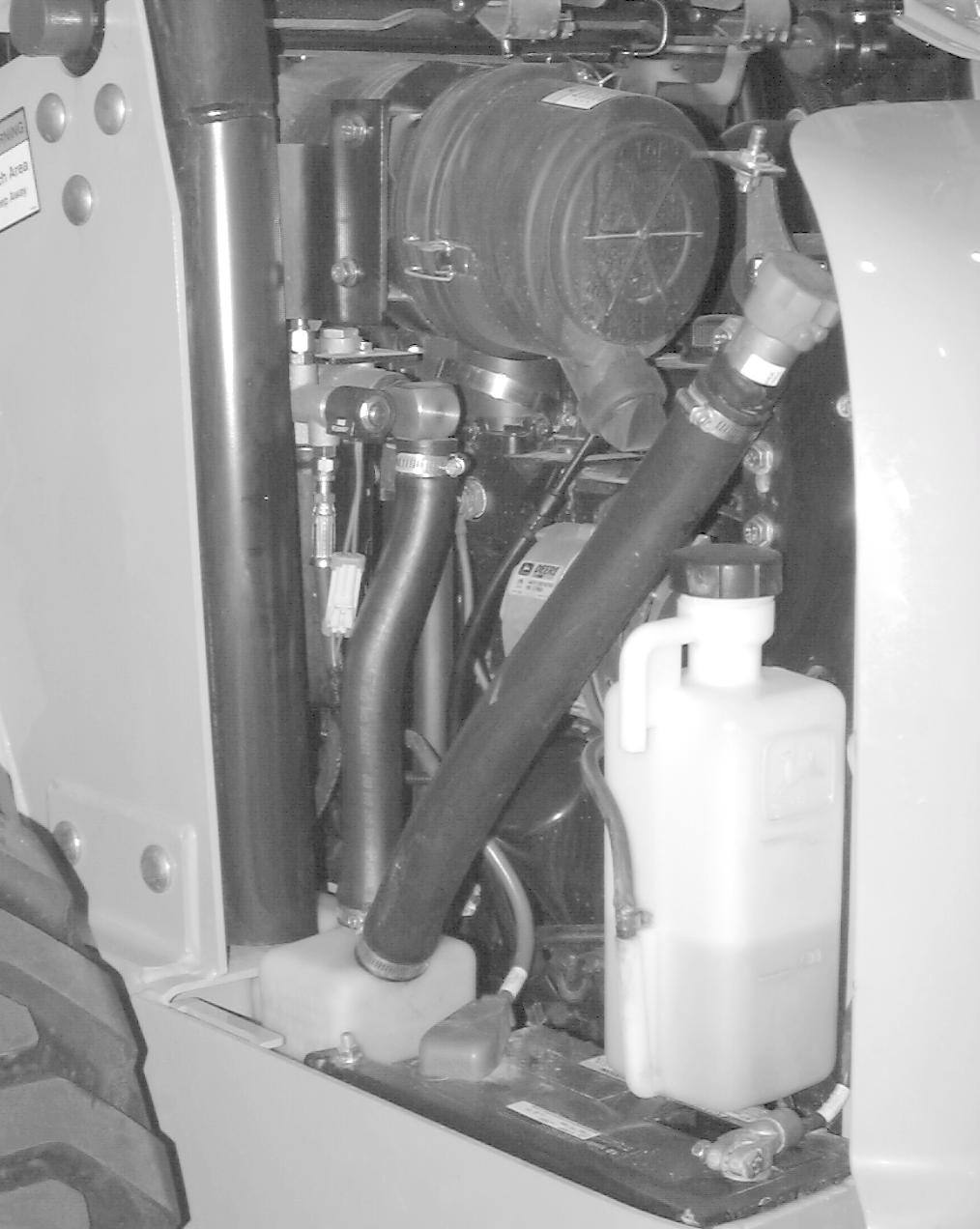
Explosive release of fluids from pressurized cooling system can cause serious burns.
Shut off machine Only remove filler cap when cool enough to touch with bare hands Slowly loosen cap to first stop to relieve pressure before removing completely.


Direct exposure to hazardous chemicals can cause serious injury. Potentially hazardous chemicals used with John Deere equipment include such items as lubricants, coolants, paints, and adhesives
A Material Safety Data Sheet (MSDS) provides specific details on chemical products: physical and health hazards, safety procedures, and emergency response techniques Check the MSDS before you start any job using a hazardous chemical That way you will know exactly what the risks are and how to do the job safely. Then follow procedures and recommended equipment
Improperly disposing of waste can threaten the environment and ecology Potentially harmful waste used with John Deere equipment include such items as oil, fuel, coolant, brake fluid, filters, and batteries Use leakproof containers when draining fluids Do not use food or beverage containers that may mislead someone into drinking from them. Do not pour waste onto the ground, down a drain, or into any water source Inquire on the proper way to recycle or dispose of waste from your local environmental or recycling center, or from your John Deere dealer.

Before returning machine to customer, make sure machine is functioning properly, especially the safety systems. Install all guards and shields.


This page intentionally left blank


Make John Deere
Type Diesel
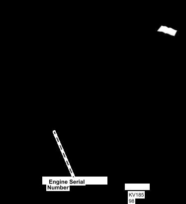
Engine Model Number
• 240 3029D
• 250 3029T
Net Horsepower at rated engine RPM (2400 RPM)
• 240 (S/N -240852) 34 3 kW (46 hp)
• 240 (S/N 240853- ) 38 kW (51 hp)
• 250 45 5 kW (61 hp)
Cylinders 3
Bore 106 mm (4 17 in )
Stroke 110 mm (4.33 in.)
Displacement 2 9 L (179 cu in )
Compression Ratio 17.8:1
Rated Engine RPM 2400
Lubrication Full pressure
Oil Filter Full flow (replaceable)
Air Cleaner Dry paper with primary and secondary elements
Cooling System Liquid-cooled
Fuel Diesel #2
Fuel Filter In-line replaceable filter
Fuel Pump Electric
Fuel Delivery Rotary injection
Type
12-volt, electric start
Charging System Alternator, 55 amp
Battery
750 CCA (cold cranking amps)
Fuel Tank 56 7 L (15 gal)
Hydraulic Reservoir 15.6 L (4.1 gal)
Hydraulic System 23 L (6 gal)
Cooling System 9 5 L (10 qt)
Engine Oil (with Filter) 6 5 L (6 9 qt)
Chain Case (per Side) 11.4 L (3 gal)
Hydrostatic Pumps
• Type Tandem variable displacement piston pump
• Displacement (Max) 40.6 cm 3 (2.48 in3) per revolution
Hydrostatic Motors
• Type GEROLER® fixed displacement 30 series
Hydraulic/Charge Pump (Standard Flow)
• 240

49.1 L/min (13 gpm)
• 250 56 7 L/min (15 gpm)
Hydraulic/Charge Pump with High-Flow (Optional)
• 240 84 8 L/min (22 4 gpm)
• 250 98.1 L/min (25.9 gpm)
Hydrostatic System Relief Pressure
34 474 kPa (5000 psi)
Charge Pressure 1448 kPa (210 psi)
Hydraulic Control Valve 3 spool open center
Filter Spin-on canister
Hydraulic System Relief Pressure
Boom Circuit Relief Pressure
21 374 kPa (3100 psi)
22 753 kPa (3300 psi)
Bucket Circuit Relief Pressure (early models only) N/A
Note: Bucket relief valve should have been removed in Safety PIP 99KV004 or 00KV007
Boom Breakout Force 1406 kg (3100 lb)
Bucket Breakout Force 2495 kg (5500 lb)
(See note below)
Operating Weight 2811 kg (6195 lb)
SAE Rated Operating Capacities 681 kg (1500 lb)
Maximum Ground Speed 11 7 km/h (7 3 mph)
Overall Operating Height 3599 mm (141 7 in )
Height to ROPS 1915 mm (75 4 in )
Height to Hinge Pin 2895 mm (114 in )
Overall Width (less Bucket) 1627 mm (64 1 in )
Overall Width (with Bucket) 1676 mm (66 in )
Overall Length (less Bucket) 2591 mm (102 in )
Overall Length (with Bucket) 3196 mm (125 8 in )
Wheelbase 1075 mm (42.3 in.)
Ground Clearance 209 mm (8 2 in )
Dump Height 2255 mm (88.8 in.)
Dump Reach 738 mm (29 1 in )
Dump Angle 45 degrees
Bucket Rollback 35 degrees
Angle of Departure 26 degrees
NOTE: Standard tires (10 x 16 5) and 66 in foundry bucket used in determining dimensions
(See note below)

Operating Weight
2854 kg (6290 lb)
SAE Rated Operating Capacities 794 kg (1750 lb)
Maximum Ground Speed 11 4 km/h (7 1 mph)
Overall Operating Height 3637 mm (143.2 in.)
Height to ROPS 1950 mm (76 8 in )
Height to Hinge Pin 2925 mm (115 2 in )
Overall Width (less Bucket) 1750 mm (68 9 in )
Overall Width (with Bucket) 1829 mm (72 in )
Overall Length (less Bucket) 2591 mm (102 in )
Overall Length (with Bucket) 3196 mm (125.8 in.)
Wheelbase 1075 mm (42 3 in )
Ground Clearance 244 mm (9.6 in.)
Dump Height 2290 mm (90 2 in )
Dump Reach 715 mm (28.1 in.)
Dump Angle 45 degrees
Bucket Rollback 35 degrees
Angle of Departure 27 degrees
NOTE: Standard tires (12 x 16.5) and 72 in. foundry bucket used in determining dimensions.
240 10 x 16 5
250 12 x 16 5
Engine Oil
PLUS-50®
John Deere TORQ-GARD SUPREME® or
(See ENGINE OIL in the ENGINE section for cold weather oil)
Engine Coolant
Hydraulic Oil and Hydrostatic Oil
Grease
John Deere COOL-GARD™
John Deere HY-GARD®
John Deere Low Viscosity HY-GARD® (cold weather operation)
John Deere HIGH TEMPERATURE EP GREASE
John Deere MOLY HIGH TEMPERATURE EP GREASE (non-clay)
Chain Case Oil
John Deere HY-GARD®
John Deere Low Viscosity HY-GARD® (cold weather operation)
John Deere TORQ-GARD SUPREME® or PLUS-50®
HY-GARD, TORQ-GARD SUPREME and PLUS-50 are is a registered trademarks of Deere & Company


DO NOT use these hand torque values if a different torque value or tightening procedure is given for a specific application. Torque values listed are for general use only and include a ±10% variance factor. Check tightness of fasteners periodically. DO NOT use air powered wrenches.
Shear bolts are designed to fail under predetermined loads Always replace shear bolts with identical grade Fasteners should be replaced with the same class Make sure fastener threads are clean and that you properly start thread engagement This will prevent them from failing when tightening When bolt and nut combination fasteners are used, torque values should be applied to the NUT instead of the bolt head
Tighten toothed or serrated-type lock nuts to the full torque value.
a. “Lubricated” means coated with a lubricant such as engine oil, or fasteners with phosphate and oil coatings. “Dry” means plain or zinc plated (yellow dichromate - Specification JDS117) without any lubrication
Reference: JDS—G200.


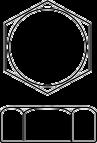
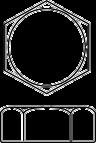
Grade and Head Markings No Marks


Markings


application Torque values listed are for general use only and include a ±10% variance factor Check tightness of fasteners periodically DO NOT use air powered wrenches
Shear bolts are designed to fail under predetermined loads. Always replace shear bolts with identical grade. Fasteners should be replaced with the same grade Make sure fastener threads are clean and that you properly start thread engagement This will prevent them from failing when tightening When bolt and nut combination fasteners are used, torque values should be applied to the NUT instead of the bolt head
Tighten toothed or serrated-type lock nuts to the full torque value
a. “Lubricated” means coated with a lubricant such as engine oil, or fasteners with phosphate and oil coatings. “Dry” means plain or zinc plated (yellow dichromate - Specification JDS117) without any lubrication
b. “Grade 2” applies for hex cap screws (not hex bolts) up to 152 mm (6-in.) long. “Grade 1” applies for hex cap screws over 152 mm (6-in ) long, and for all other types of bolts and screws of any length
Reference: JDS—G200.


Stud End
Tube Nut


Stud Straight and Tube Nut


Bulkhead Union and Bulkhead Lock Nut

Lock Nut
Stud End
90° Adjustable Stud Elbow
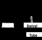
90° Swivel Elbow and Tube Nut
NOTE: Torque tolerance is plus 15 minus 20%


Stud End


Nut Groove For Metric Identification
Straight and Tube Nut


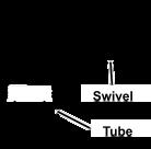
End 90° Swivel Elbow and Tube Nut Bulkhead Union and Bulkhead Lock Nut

NOTE: Torque tolerance is plus 15


Sealing Surface


Sealing Surface
1. Inspect the fitting sealing surfaces. They must be free of dirt or defects
2 Inspect the O-ring It must be free of damage or defects
3 Lubricate O-rings and install into groove using petroleum jelly to hold in place
4. Push O-ring into the groove with plenty of petroleum jelly so O-ring is not displaced during assembly.
5 Index angle fittings and tighten by hand pressing joint together to insure O-ring remains in place
6. Tighten fitting or nut to torque value shown on the chart per dash size stamped on the fitting Do not allow hoses to twist when tightening fittings
1 Inspect boss O-ring boss seat It must be free of dirt and defects If repeated leaks occur, inspect for defects with a magnifying glass Some raised defects can be removed with a slip stone


2 Put hydraulic oil or petroleum jelly on the O-ring Place electrical tape over the threads to protect Oring from nicks Slide O-ring over the tape and into the groove of fitting Remove tape
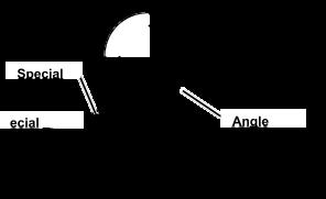
3. For angle fittings, loosen special nut and push special washer against threads so O-ring can be installed into the groove of fitting.
4 Turn fitting into the boss by hand until special washer or washer face (straight fitting) contacts boss face and O-ring is squeezed into its seat
5 To position angle fittings, turn the fitting counter- clockwise a maximum of one turn
6 Tighten straight fittings to torque value shown on chart. For angle fittings, tighten the special nut to value shown in the chart while holding body of fitting with a wrench.
STRAIGHT FITTING OR SPECIAL NUT TORQUE
3/8-24 UNF 8 (6) 2
7/16-20 UNF 12 (9) 2
1/2-20 UNF 16 (12) 2 9/16-18 UNF 24 (18) 2
3/4-16 UNF 46 (34) 2
7/8-14 UNF 62 (46) 1-1/2
1-1/16-12 UN 102 (75) 1
1-3/16-12 UN 122 (90) 1
1-5/16-12 UN 142 (105) 3/4
1-5/8-12 UN 190 (140) 3/4
1-7/8-12 UN 217 (160) 1/2
a. Torque tolerance is ± 10%.
b. To be used if a torque wrench cannot be used. After tightening fitting by hand, put a mark on nut or boss; then tighten special nut or straight fitting the number of flats shown.
In general, diesel fuels are blended to satisfy the low air temperature requirements of the geographical area in which they are sold
• Use Grade No. 2-D fuel at temperatures above 4°C (40°F).
• For maximum filter life, sediment and water should not be more than 0 10%
• The cetane number should be 45 minimum. If you operate your machine where air temperatures are normally low or in high altitudes, you may need fuel with a higher cetane number
• Cloud Point - For cold weather operation, cloud point should be 6°C (10°F) below lowest normal air temperature.
• In winter use special winter fuel or add an antigelling compound to fuel to maintain its proper viscosity
If diesel fuel being used has a sulfur content greater than 0.5%, reduce the service interval for engine oil and filter by 50%
Bio-Diesel Fuels with bio-degradable properties that meet specification DIN 51606 or equivalent may be used
Consult your local diesel fuel distributor for properties of the diesel fuel available in your area.
Diesel fuel must have adequate lubricity to ensure proper operation and durability of fuel injection system components Fuel lubricity should pass a minimum of 3300 gram load level as measured by the BOCLE scuffing test
IMPORTANT: DO NOT USE GALVANIZED CONTAINERS—diesel fuel stored in galvanized containers reacts with zinc coating in the container to form zinc flakes. If fuel contains water, a zinc gel will also form. The gel and flakes will quickly plug fuel filters and damage fuel injectors and injection pumps.
It is recommended that diesel fuel be stored ONLY in a clean, approved POLYETHYLENE PLASTIC container WITHOUT any metal screen or filter This will help prevent any accidental sparks from occurring Store fuel in an area that is well ventilated to prevent possible igniting of fumes by an open flame or spark, this includes any appliance with a pilot light.
IMPORTANT: Keep all dirt, scale, water or other foreign material out of fuel.
Keep fuel in a safe, protected area and in a clean, properly marked (“DIESEL FUEL”) container DO NOT use de-icers to attempt to remove water from fuel DO NOT depend on fuel filters to remove water from fuel It is recommended that a water separator be installed in the storage tank outlet BE SURE to properly discard unstable or contaminated diesel fuel and/or their containers when necessary


Use the appropriate oil viscosity based on the expected air temperature range during the period between recommended oil changes Operating outside of these recommended oil air temperature ranges may cause premature engine failure
The following oil is preferred AFTER first 100 hours of break-in oil is used:
• John Deere TORQ-GARD SUPREME or John Deere PLUS-50


Other oils may be used if they meet one of the following:
•API Service Classification CE


•API Service Cl ssification CD
•CCMC Specification D5

•CCMC Specification D4
If John Deere TORQ-GARD SUPREME or John Deere PLUS-50 engine oil and a John Deere oil filter are used after first 100 hours, the oil and filter service interval may be extended by 50%.
If diesel fuel exceeding 0 5% sulfur content is used, reduce the service interval for engine oil and filter by 50%
Oils meeting Military Specification MIL-L-46167B may be used as arctic oils


IMPORTANT: ONLY use this specified break-in oil in rebuilt or remanufactured engines for the first 100 hours (maximum) of operation DO NOT use PLUS-50® , SAE 15W40 oil or oils meeting specifications API CG-4 or API CF-4, these oils will not allow rebuilt or remanufactured engines to break in properly.
The following John Deere oil is PREFERRED:
•BREAK-IN ENGINE OIL
John Deere BREAK-IN ENGINE OIL is formulated with special additives for aluminum and cast iron type engines to allow the power cylinder components (pistons, rings, and liners as well) to “wear in” while protecting other engine components, valve train and gears, from abnormal wear Engine rebuild instructions should be followed closely to determine if special requirements are necessary
John Deere BREAK-IN ENGINE OIL is also recommended for non-John Deere engines, both aluminum and cast iron types.
If this preferred John Deere oil is not available, use a break-in engine oil meeting the following specification during the first 100 hours of operation:
•API Service Classification CE or higher.
IMPORTANT: After the break-in period, use the John Deere oil that is recommended for this engine.

Use the following oil viscosity based on the air temperature range. Operating outside of the recommended oil air temperature range may cause premature hydrostatic transmission or hydraulic system failures
IMPORTANT: DO NOT use BIO-HY-GARD® in this system.
The following John Deere engine oils are PREFERRED:
•John Deere HY-GARD® .
• John Deere low viscosity HY-GARD® (cold weather operation only).


Use the following oil viscosity based on the air temperature range Operating outside of the recommended oil air temperature range may cause premature chain case failure.


IMPO ANT: DO NOT use BIO-HY-GARD® in this ch n case.

The following John Deere oils are PREFERRED:
• John Deere HY-GARD®
• John Deere Low Viscosity HY-GARD® (cold weather operation)


• John Deere TORQ-GARD SUPREME or PLUS-50
Other oils may be used if above preferred John Deere oils are not available, provided they meet the following specification:
•API Service Classification SG or higher


Use the following grease based on the air temperature range Operating outside of the recommended grease air temperature range may cause premature failures.
IMPORTANT: ONLY use a quality grease in this application. DO NOT mix any other greases in this application. DO NOT use any BIO-GREASE in this application.
The following John Deere greases are PREFERRED:
• John Deere MOLY HIGH TEMPERATURE EP GREASE
• John Deere HIGH TEMPERATURE EP GREASE (Non-Clay)
Other greases may be used if they meet one of the following:
• SAE Multipurpose EP Grease with a maximum of 5% molybdenum disulfide
•SAE Multipurpose EP Grease


The engine cooling system, when filled with a proper dilution mixture of anti-freeze and deionized or distilled water, provides year-round protection against corrosion, cylinder or liner pitting, and winter freeze protection down to –37°C (–34°F)
The following John Deere coolants are PREFERRED:
•John Deere COOL-GARD
•John Deere ANTIFREEZE/SUMMER COOLANT
These coolants satisfy specifications for “Automobile and Light Duty Engine Service” and are safe for use in John Deere Lawn and Grounds Care/Golf and Turf Division equipment, including aluminum block gasoline engines and cooling systems.
The above preferred pre-diluted coolants provide:
•adequate heat transfer
• corrosion-resistant chemicals for the cooling system
• compatibility with cooling system hose and seal material

G eases meeting Military Specification MIL-G-10924F m y be used as arctic grease


• protection during extreme cold and extreme hot weather operations
•chemically pure water for better service life
• compliance with ASTM D4656 (JDM H24C2) specifications
If above preferred pre-diluted coolants are not available, the following John Deere concentrate is recommended:
• DIESEL ENGINE
ANTI-FREEZE/SUMMER COOLANT CONCENTRATE™ (TY16034).
If the above recommended engine coolants are not available use any Automobile and Light Duty Engine Service ethylene glycol base coolant, meeting the following specification:
•ASTM D3306 (JDM H24C1)
Read container label completely before using and follow instructions as stated


IMPORTANT: To prevent engine damage, DO NOT use pure anti-freeze or less than a 50% antifreeze mixture in the cooling system. Water used to dilute engine coolant concentrate must be of high quality clean, clear, potable water (low in chloride and hardness see table below) is generally acceptable. DO NOT use salt water. Deionized or distilled water is ideal to use. Coolant that is not mixed to these specified levels and water purity can cause excessive scale, sludge deposits, and increased corrosion potential
Property Requirements
Total Solids, Maximum 340 ppm (20 grns/gal)
Total Hardness, Max 170 ppm (10 grns/gal)
Chloride (as Cl), Max 40 ppm (2 5 grns/gal)
Sulfate (as SO4), Max 100 ppm (5 8 grns/gal)
Mix 50 percent anti-freeze concentrate with 50 percent distilled or deionized water. This mixture and the prediluted mixture (TY16036) will protect the cooling system down to –37°C (–34°F) and up to 108°C (226°F).
Certain geographical areas may require lower air temperature protection See the label on your antifreeze container or consult your John Deere dealer to obtain the latest information and recommendations
The concentration of coolant additives is gradually depleted during engine operation. For all recommended coolants, replenish additives between drain intervals by adding a supplemental coolant additive every 12 months or as determined necessary by coolant testing
John Deere COOLANT CONDITIONER is recommended as a supplemental coolant additive in John Deere engines.
IMPORTANT: Do not add a supplemental coolant additives when the cooling system is drained and refilled with John Deere ANTIFREEZE/ SUMMER COOLANT or John Deere COOLGARD.
If other coolants are used, consult the coolant supplier and follow the manufacturer’s recommendation for use of supplemental coolant additives
The use of non-recommended supplemental coolant additives may result in additive drop-out and gelation of the coolant
Add the manufacturer’s recommended concentration of supplemental coolant additive DO NOT add more than the recommended amount
When using John Deere Concentrate (TY16034) Automobile and Light Duty Engine Service coolants, drain and flush the cooling system and refill with fresh coolant mixture every 24 months or 2,000 hours of operation, whichever comes first
If above John Deere Automobile and Light Duty Engine Service coolants are not being used, drain, flush, and refill the cooling system according to instructions found on product container or in equipment operator’s manual or technical manual
ty claim, it is eer product nent serial
tion number


This page intentionally left blank


