The manual would likely provide detailed information on the engine, including specifications, maintenance procedures, troubleshooting guides, and potential repair procedures.
3170, 3170 Plus 3190, 3190 Plus 3200, 3200 Plus 3220, 3220 Plus 3230, 3230 Plus
Routine Maintenance
Optional Equipment A Body & Framework B
Electrics C Controls
Hydraulics
by the TECHNICAL PUBLICATIONS DEPARTMENT of JCB SERVICE LTD; World Parts Centre, Waterloo Park Uttoxeter, Staffordshire ST14 7BS Publication No. 9803/8030 Issue 9 General Information 1 Care & Safety 2 3
D
E Transmission F Brakes G Steering H Suspension S Engine T
Introduction
This publication is designed for the benefit of JCB Distributor Service Engineers who are receiving, or have received, training by JCB Technical Training Department.
These personnel should have a sound knowledge of workshop practice, safety procedures, and general techniques associated with the maintenance and repair of hydraulic earthmoving equipment.
Renewal of oil seals, gaskets, etc., and any component showing obvious signs of wear or damage is expected as a matter of course. It is expected that components will be cleaned and lubricated where appropriate, and that any opened hose or pipe connections will be blanked to prevent excessive loss of hydraulic fluid and ingress of dirt. Finally, please remember above all else
SAFETY MUST COME FIRST!
The manual is compiled in sections, the first three are numbered and contain information as follows:
1=General Information - includes torque settings and service tools.
2=Care & Safety - includes warnings and cautions pertinent to aspects of workshop procedures etc.
3=Routine Maintenance - includes service schedules and recommended lubricants for the whole machine.
The remaining sections are alphabetically coded and deal with Dismantling, Overhaul etc. of specific components, for example:
A= Optional Equipment
B=Body & Framework ...etc
The page numbering in each alphabetically coded section is not continuous. This allows for the insertion of new items in later issues of the manual.
Section contents, technical data, circuit descriptions, operation descriptions etc. are inserted at the beginning of each alphabetically coded section.
All sections are listed on the front cover; tabbed divider cards align directly with individual sections on the front cover for rapid reference.
Page cross references are generally made by presenting the subject title printed in bold, followed by the title of the section containing the subject. For example:
“24 If the axle is still on the machine, fit the brake calipers (see Brake Caliper Removal and Replacement, Section G).”
Note: If only the subject title in bold is given, i.e. no section title, the cross reference is to another part of the same section.
Use the contents list at the beginning of each section to find the exact page number.
Where a torque setting is given as a single figure it may be varied by plus or minus 3%. Torque figures indicated are for dry threads, hence for lubricated threads may be reduced by one third.
‘Left Hand’ and ‘Right Hand’ are as viewed from the rear of the machine facing forwards.
Serial Number Plate
Each machine has a serial number plate located at X. The 17 digit Vehicle Identification Number (VIN), and the serial numbers of the engine and transmission are stamped on the plate.
Typical Vehicle Identification No. (VIN)
Original VIN Configuration
Later VIN Configuration
A = Manufacturing Code
B = Machine Range
FT = Fastrac
C = Engine Type
17 = 3190 or 3190 Plus
18 = 3220 or 3220 Plus
19 = 3170 or 3170 Plus
23 = 3200 or 3200 Plus 24 = 3230 or 3230 Plus
D = Transmission Type (Gearbox and axle combination) 3170, 3170 Plus All other machines
A = 75 km/h 8 = Standard (40, 50 or 65 km/h)
B = 65 km/h 9 = High Speed (75 km/h)
D = 50 km/h
E = 40 km/h
E = Vehicle Max. Speed
40 = 40 km/h
50 = 50 km/h
65 = 65 km/h
75 = 75 km/h
F = Serial Number
G = Authenticity Code
H = year Code (e.g. 6 = 2006)
Unit Identification
The serial number of each major unit is also stamped on the unit itself as shown below. If a major unit is replaced by a new one, the serial number on the plate will be wrong. Either stamp the new number of the unit on the identification plate, or simply stamp out the old number. This will prevent the wrong unit number being quoted when replacement parts are ordered.
Engine M
Gearbox Assembly (assembly of all three gearboxes) N
Speed Gearbox P
Front Axle R
Rear Axle S
S P X R M N
Section 1 General Information
Torque Settings
Introduction - Zinc Plated Fasteners and Dacromet Fasteners
Some external fasteners on Fastrac machines are assembled using an improved type of corrosion resistant finish. This type of finish is called Dacromet and replaces the original Zinc and Yellow plating used on earlier machines.
The two types of fasteners can be readily identified by colour and part number suffix as follows:
Note: As the Dacromet fasteners have a lower torque setting than the Zinc and Yellow fasteners, the torque figures used must be relevant to the type of fasteners.
Note: A Dacromet bolt should not be used in conjunction with a Zinc and Yellow plated nut, as this could change the torque characteristics of the torque settings further. For the same reason, a Dacromet nut should not be used in conjunction with a Zinc and Yellow plated bolt.
Note: All bolts used on JCB machines are high tensile and must not be replaced by bolts of a lesser tensile specification.
Note: Dacromet bolts, due to their high corrosion resistance are used areas where rust could occur. Dacromet bolts are only used for external applications. They are not used in application such as gearbox and engine joint seams or internal applications.
Torque Settings
Zinc Plated Fasteners (golden finish)
Use only where no torque setting is specified in the text. Values are for dry threads and may be within three per cent of the figures stated. For lubricated threads the values should be REDUCED by one third.
Metric Grade 8.8 Bolts
Bolt sizeTorque Settings
Dia.(mm)Hexagon Nmkgf mlbf ft (A/F) mm
M5(5)870.75
M6(6)10121.29
M8(8)13283.021
M10(10)17565.742
M12(12)19981072
M16(16)2424425180
M18(18)2735036258
M20(20)3047648352
M24(24)3682284607
M30(30)4616331661205
M36(36)5528542912105
Metric Grade 10.9 Bolts
Bolt sizeTorque Settings Dia.(mm)Hexagon Nmkgf mlbf ft (A/F) mm
Gasketing - Loctite 509 To seal the joint faces between the PTO/splitter gearbox, the 4102/3202 50ml speed gearbox and the range gearbox.4102/3240315 ml
JCB Multigasket A medium strength sealant suitable for all sizes of gasket flanges, and for hydraulic fittings of 25-65 mm diameter.4102/1212
JCB High Strength Threadlocker A high strength locking fluid for use with threaded components. 4102/0551 Gasketing for all sizes of flange where the strength of the joint is important.
JCB Retainer (High Strength) For all retaining parts which are unlikely to be dismantled. 4101/0651
JCB Threadlocker & Sealer A medium strength locking fluid for sealing and retaining nuts, bolts, and screws up to 50 mm diameter, and for hydraulic fittings up to 25 mm diameter.4101/0251
JCBThreadlocker For threads of suction strainer.4101/045150ml
JCB Threadlocker & Sealer A medium to high strength locking fluid. 4101/0552 (High Strength)
JCB Threadseal Medium strength thread sealant (for patch bolts that are re-used).4102/195150 ml
Clayton System Seal SC1251 A thread sealant used mainly on air brake system hose adapters.4102/22102ml
JCB Activator A cleaning primer which speeds the curing rate of anaerobic 4104/0251Aerosol products.4104/0253Bottle
JCB Cleaner/Degreaser For degreasing components prior to use of anaerobic adhesives and sealants. 4104/1557Aerosol
Direct Glazing Kit For one pane of glass, comprises items marked † below plus applicator nozzle etc.993/55700
† Ultra Fast Adhesive For direct glazing4103/2109310 ml
† Active Wipe 205 For direct glazing4104/1203250 g 4104/120630 ml
† Black Primer 206J For direct glazing4201/490630 ml
JCB Clear Silicone Sealant To seal butt jointed glass. Also to seal hub planet gear carrier when no 'O' ring is fitted4102/0901
Black Polyurethane Sealant To finish exposed edges of laminated glass4102/2309310 ml
Section 1
Service Tools Numerical List
1370/0901ZNut M249 -
1406/0021Bonded Washer7 - 1
1604/0006Adapter7 - 1
1604/0008Adapter7 - 1
1606/0012Adapter7 - 1
1606/0015Adapter7 - 1
1612/0006Adapter7 - 1
4101/0251JCB Threadlocker and Sealer3 -
4101/0451JCB Threadlocker3 -
4101/0552JCB Threadlocker and Sealer (High Strength)3 -
4101/0651JCB Retainer (High Strength)3 -
4102/0551JCB High Strength Threadlocker3 - 1
4102/0901JCB Clear Silicone Sealant3 - 1
4102/1212JCB Multigasket3 - 1
4102/1951JCB Threadseal3 - 1
4102/2210Clayton System Seal SC12513 -
4102/2309Black Polyurethane Sealant3 -
4103/2109Ultra Fast Adhesive3 -
4104/0251JCB Activator (Aerosol)3 -
4104/0253JCB Activator (Bottle)3 -
4104/1557JCB Cleaner/Degreaser3 -
4104/1203Active Wipe 205 (250 g)3
4104/1206Active Wipe 205 (30 ml)3
4104/1310Hand Cleaner5 -
4201/4906Black Primer3 -
721/00664Connecting Lead (Wingst)6
721/10885Harness - ABS Diagnostic (J1939)6
816/15118Test Adapter7
816/55038Adapter/Test Point7 -
816/55040Adapter/Test Point7 -
892/00041Deglazing Tool9
892/00078Connector7 -
892/00137Micro Bore Hose7 -
892/00174Measuring
892/00179Bearing Press8
892/00223Hand Pump7
892/00224Impulse Extractor
892/00225Adapter for Impulse Extractor8
892/00253Pressure Test Kit7
892/00255Adapter/Test Point7 -
892/00256Adapter/Test Point7 -
892/00257Adapter/Test Point7 -
892/00258Adapter/Test Point7 -
892/00259Adapter/Test Point7 -
892/00260Adapter/Test Point7
892/00261Adapter/Test Point7
892/00262Adapter/Test Point7 -
892/00263Adapter/Test Point7 -
892/00264Adapter/Test Point7
892/00265Adapter/Test Point7
892/00268Flow
892/00278Gauge
892/00279Gauge
892/00282Shunt6
892/00284Digital Tachometer6 -
892/00285Oil Temperature Probe6 -
892/00286Surface Temperature Probe6 -
Multimeter6
892/00311Brake Test
993/70111Break-back
997/11000Drive
The following parts are replacement items for kits and would normally be included in the relevant kit numbers.
Replacement items for kit no. 892/00253
Replacement parts for kit no. 892/01092
Section A - Optional Equipment
1992/09000Peg spanner for piston head of front hitch ram (including 2 pairs of pegs)
2992/09003Replacement pegs for 7.5 mm holes
3992/09004Replacement pegs for 10 mm holes
892/00334Gland Seal Fitting Tool
Section 1 General Information
Service Tools
Section B - Body and Framework
Hand Cleaner - special blend for the removal of polyurethane adhesives.
JCB part number - 4104/1310 (454g; 1lb tub)
Cartridge Gun - hand operated - essential for the application of sealants, polyurethane materials etc.
JCB part number - 892/00845
12V Mobile Oven - 1 cartridge capacity - required to pre-heat adhesive prior to use. It is fitted with a male plug (703/23201) which fits into a female socket (715/04300).
JCB part number - 992/12300
Folding Stand for Holding Glass - essential for preparing new glass prior to installation.
JCB part number - 892/00843
S186260
240V Static Oven - available with 2 or 6 cartridge capacity - required to pre-heat adhesive prior to use. No plug supplied. Note: 110V models available upon request - contact JCB Technical Service
JCB part number: 992/12400 - 2 cartridge x 240V 992/12600 - 6 cartridge x 240V
Glass Lifter - minimum 2 off - essential for glass installation, 2 required to handle large panes of glass. Ensure suction cups are protected from damage during storage.
JCB part number - 892/00842
S186240
S186250
S186270
S186280
S186300
Service Tools (continued)
Section B - Body and Framework (continued)
Wire Starter - used to access braided cutting wire (below) through original polyurethane seal.
JCB part number - 892/00848
S186320
Glass Extractor (Handles) - used with braided cutting wire (below) to cut out broken glass.
JCB part number - 892/00846
Braided Cutting Wire - consumable heavy duty cut-out wire used with the glass extraction tool (above).
JCB part number - 992/12801 (unit quantity = 5 off)
Long Knife - used to give extended reach fornormally inaccessible areas.
JCB part number - 892/00844
S186310
S186330
S186340
S186350
S186360
Service Tools (continued)
Section B - Body and Framework (continued)
S186470
Nylon Spatula - general tool used for smoothing sealants - also used to re-install glass in rubber glazing because metal tools will chip the glass edge.
JCB part number - 892/00847
S186550
Rubber Spacer Blocks - used to provide the correct set clearance between glass edge and cab frame.
JCB part number - 926/15500 (unit quantity = 500 off)
892/00801Clutch spanner
S200940 for air conditioning compressor
892/00802Rotor puller set
S200950 for air conditioning compressor
892/00803Rotor installer set
S200960 for air conditioning compressor
892/00807Front plate puller
S200970 for air conditioning compressor
892/00808Shaft protector
S200980 for air conditioning compressor
Section C - Electrics
Electrical Test Equipment
1 892/00283Tool Kit Case
2 892/00281AVOMeter
3 892/00286Surface Temperature Probe
4 892/00284Microtach Digital Tachometer
5 892/00282100 Amp Shunt - open type
6 892/00285Hydraulic Oil Temperature Probe
7 892/00298Fluke 85 Multimeter
A892/01033 Data Link Adapter Kit - ABS
Note: Item A of the Data Link Adapter Kit is unsuitable for use with the Fastrac and must be replaced by the ‘Harness - Diagnostic (J1939)’ shown below.
721/10885Harness - Diagnostic (J1939)
A386040
A360250
Section C - Electrics (continued)
721/00664Connecting Lead - Wingst
A406950
892/01066Combination Lead (alternative to 721/00664)
Service Tools
Section E - Hydraulics
Pressure Test 'T' Adapters
892/002621/4 in M BSP x 1/4 in F BSP x Test Point
816/550383/8 in M BSP x 3/8 in F BSP x Test Point
816/550401/2 in M BSP x 1/2 in F BSP x Test Point
892/002635/8 in M BSP x 5/8 in F BSP x Test Point
892/002643/4 in M BSP x 3/4 in F BSP x Test Point
892/002651 in M BSP x 1 in F BSP x Test Point
Hydraulic Circuit Pressure Test Kit
892/00253Pressure Test Kit
892/00201Replacement Gauge 0-20 bar (0-300 lbf/in2)
892/00202Replacement Gauge 0-40 bar (0-600 lbf/in2)
892/00203Replacement Gauge 0-400 bar (0-6000 lbf/in2)
892/00254Replacement Hose
:993/69800 Seal Kit for 892/00254 (can also be used with probe 892/00706)
Flow Test Equipment
892/00268Flow Monitoring Unit
892/00269Sensor Head 0 - 100 l/min (0 - 22 UK gal/min)
892/00293Connector Pipe
892/00270Load Valve
1406/0021Bonded Washer
1604/0006Adapter 3/4 in M x 3/4 in M BSP
1612/0006Adapter 3/4 in F x 3/4 in M BSP
892/00271Adapter 3/4 in F x 5/8 in M BSP
892/00272Adapter 5/8 in F x 3/4 in M BSP
816/20008Adapter 3/4 in F x 1/2 in M BSP
892/00275Adapter 1/2 in F x 3/4 in M BSP
892/00276Adapter 3/4 in F x 3/8 in M BSP
892/00277Adapter 3/8 in F x 3/4 in M BSP
892/00273Sensor Head 0 - 380 l/min
892/00294Connector Pipe
1606/0015Adapter 1.1/4 in M BSP x 1 in M BSP
892/00078Connector 1 in F x 1 in F BSP
1604/0008Adapter 1 in M x 1 in M BSP
1606/0012Adapter 1 in M x 3/4 in M BSP
816/20013Adapter 3/4 in F x 1 in M BSP
Pressure Test Adapters
892/002551/4 in BSP x Test Point
892/002563/8 in BSP x Test Point
892/002571/2 in BSP x Test Point
892/002585/8 in BSP x Test Point
816/151183/4 in BSP x Test Point
892/002591 in BSP x Test Point
892/002601.1/4 in BSP x Test Point
892/002615/8 in UNF x Test Point
S188130
S188120
S200140
S188150
Section 1 General Information
Service Tools (continued)
Section E - Hydraulics (continued)
Hand Pump Equipment
892/00223Hand Pump
892/00137Micro-bore Hose 1/4 in BSPx 5 metres
892/00274Adapter 1/4 in BSP male x 3/8 BSPTmale
892/00262Test Point on 1/4 in BSPmale x 1/4 BSP female adapter
892/00706Test Probe
892/00278Gauge 0-40 bar (0-600 lbf/in2)
892/00279Gauge 0-400 bar (0-6000 lbf/in2)
892/00318Hose And Adapter Kit
To enable flow and pressure test equipment to be connected to adapters fitted with 'O' ringface seals.
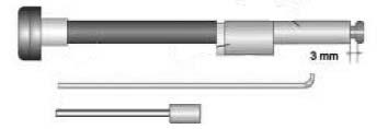
892/00334Gland Seal Fitting Tool
331/64265 Retaining Bush for Valve Spool
331/64246Tool Kit for Non-return Valve
Service Tools
Section F - Transmission
892/00179Bearing Press
892/00812PTO Drive Coupling Spanner for yoke couplings
892/00225Adapter - Impulse Extractor
Small17mm to 25mm
Medium25mm to 45mm
Large45mm to 80mm
Differential Setting Key Cut from 5 mm plate to dimensions shown. Fabricate handle to suit.
993/45400Torque Multiplier (use in conjunction with a torque wrench to give a 5 : 1 multiplication)
Service Tools (continued)
Section F - Transmission (continued)
Heavy Duty Sockets
892/0081717 mm A/F x 3/4in. square drive
892/0081822 mm A/F x 3/4in. square drive
892/0081915 mm A/F x 1/2in. square drive
892/0033319 mm A/F x 3/4in. square drive
892/00174Measuring Cup - Pinion Head Bearing
892/00224Impulse Extractor Set for Hub Bearing Seals
892/01053Adapter for impulse extractor (PTO intermediate shaft, wet clutch transmission)
892/00312Dummy End Plate for Range Gearbox
993/593002/4 WD Pressure Test Adaptor & Clamp
S197240
S190770 S196750
Service Tools (continued)
Section F - Transmission (continued)
S226300
892/00892Speed Gearbox Locking Tool
892/00916Spring Compressor for Splitter and PTO Clutches
S267310
A270851 4 3 A B 2 1 C
Solid Spacer Setting Tools
1 892/00918Setting Tool Kit. Contains the following:
A Sleeve for M24 Pinion
B Adapter for M30 Pinion
C Fork (suitable for all axles)
The following setting tools must be purchased seperately:
892/00945 A Sleeve for M30 Pinion
997/11100 B Adapter for M24 Pinion
2 997/11000Drive Head Setting Bracket
3 993/70111Break-back Torque Wrench
4 -Solid spacer (see parts CD or michrofiche for part numbers)
892/00864PD 90 Axle Locknut Spanner
A361730
892/01052 (x2)Locking Plate for locking wet clutch drum to housing
892/01047Jig, for use when dismantling and assembling of PTO input gear - wet clutch
892/01049 (x2)Guide Rod - wet clutch
A361740
892/01046Mandrel - for bush assembly - wet clutch
A361770
892/01048 (x2) Clutch Pack Retainer - wet clutch
A361720
892/01050Mandrel, for hub seal renewal - wet clutch. Note: Protective plastic cap A to be removed before use.
A361780
Section G - Brakes
Section H - Steering
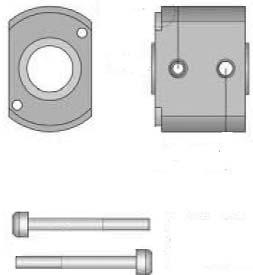
Puller adapter assembly for removal of drop arm from steering box (3000 Series machines). Comprises:
A 892/00871Frame1 off
B 892/00874Brace1 off
C 892/00875Bar M242 off
D 892/00876Block2 off E 1370/0901ZNut M242 off
Use in conjunction with a 20 tonne hydraulic ram as obtainable from Sykes Pickavant to suit puller bars at 185 mm centres.
892/00311Brake Test Kit
3 x Calibrated Test Gauges - 0-20 bar (0 - 290 lbf/in2)
3 x 5 Metre Hoses with Quick Release Adapters
3 x ISO Test Point Adapters
Service Tools (continued)
Section S - Suspension
S199480
892/00314Accumulator and Gas Spring Pressure Test Adapter
Section T - Engine
S192390
892/00041De-glazing Tool for Cylinder Bores (to assist bedding-in of new piston rings)
Note: For other engine tools refer to the relevant Engine Service Manual.
Section 1 General Information
Moving a Disabled Machine
General
Do not tow a machine unless there is no alternative. Remember that more damage might be caused to the machine by towing it. If at all possible repair the machine where it stands.
Note: It is not possible to tow-start or push-start the Fastrac due to the design of the transmission.
Make sure you will be obeying all pertinent laws and regulations before towing the machine on public roads.
! DANGER
If the engine is not running, there will not be enough air to apply the service brakes or release the parking brake. Carefully follow the precautions in this section before moving the machine or there may be a serious accident.
13-2-2-6/1
! CAUTION
Towing a machine too far or too fast can damage the transmission. Do not tow the machine further than one mile. Use a trailer for greater distances. When towing do not travel faster than 25 km/h (15 mph).
Use a rigid drawbar. If you must use towing chains, then use two towing vehicles. One towing vehicle should be coupled to the front of the disabled machine. The other towing vehicle should be coupled to the rear of the disabled machine, to provide braking power.
The towing vehicle(s) must have enough pulling and braking power to move and stop the machine.
2-2-7-3
Preparation for Towing
1Connect the towing vehicle.
a Apply the parking brakes on the towing vehicle and securely chock the wheels on the Fastrac.
b Fit the drawbar between towing vehicle and Fastrac.
2Prepare the machine.
a Make sure that the range and speed gearboxes are both in neutral.
b If the gearbox has failed, disconnect both propshafts (see Section F).
c If an axle has failed, remove the sun gears (see Section F).
3Release the Fastrac parking brake.
If there is not enough air pressure to release the brake, start the engine to charge up the air system. If the engine cannot be run but the brake air system is serviceable, charge the system to 8 bar (120 lbf/in2) through Schrader valve X (machines with ABS)or Y (machines without ABS). This job must be done by a qualified mechanic, using the correct equipment.
! DANGER
Ensure that the chocks and towing vehicle will prevent the Fastrac from moving as it is necessary to work under the machine to remove the propshafts or release the parking brake. When the propshafts have been disconnected the parking brake cannot prevent the machine from moving. When the parking brake has been manually released as described below, it will be impossible to apply the brake until plate A has been removed and the propshafts connected. Anyone working underneath, or near the machine, could be killed or seriously injured if the machine moved.
13-2-2-11/1
Alternatively, position plate A (if provided with the machine) as shown. Keeping nut B tight against clevis C, turn nut D against the plate so that rod E is drawn out of the actuator body and the parking brake is released.
Note: If the parking brake cannot be released, remove both propshafts (see Section F).
The machine is now ready for towing. If you will be steering the Fastrac, make sure you understand what the towing driver will be doing. Obey his instructions and all relevant regulations.Remember that the steering will be much heavier if the engine is not running.
Section 1 General Information
Transporting the Machine
The safe transit of the load is the responsibility of the transport contractor and driver. Any machine, attachments or parts that may move during transit must be adequately secured.
5-2-5-9
Note: Before transporting the machine make sure you will be obeying the rules and laws of all the areas that the machine will be carried through.
Make sure that the transporting vehicle is suitable. See Static Dimensions (SPECIFICATIONS section in the machine handbook) for the dimensions of the machine.
! WARNING
Before moving the machine onto the trailer, make sure that the trailer and ramp are free from oil, grease and ice. Remove oil, grease and ice from the machine tyres. Make sure the machine will not foul on the ramp angle. See Static Dimensions in SPECIFICATIONS section for the minimum ground clearance of your machine.
2-2-7-5/1
1 Place blocks at the front and rear of the trailer wheels.
2 Move the machine on to the trailer as follows:
a Make sure the ramps are correctly in place and secure.
b Carefully drive the machine onto the trailer.
c Set the drive to neutral and engage the parking brake.
d Switch off the engine.
e Ensure that the overall height of the load is within regulations.
f Secure the cab.
3 Anchor the machine to the trailer with chains or suitable webbing straps. The preferred fixing is to use webbing straps individually fixing all four wheels to the deck of the trailer as at A. If chains are used they should be connected to a suitable part of the drawbar at the rear of the machine. At the front, use the tie down points B Avoid chaining any part of the machine where the chains may damage critical componentry. For example, chaining around either axle provides the possibility of damaging the steel brake pipes running along their length.
4 Measure the maximum height of the machine from the ground. Try to make sure the truck driver knows the clearance height before he drives away.
In this publication and on the machine, there are safety notices. Each notice starts with a signal word. The signal word meanings are given below.
! DANGER
Denotes an extreme hazard exists. If proper precautions are not taken, it is highly probable that the operator (or others) could be killed or seriously injured.
INT-1-2-1
! WARNING
Denotes a hazard exists. If proper precautions are not taken, the operator (or others) could be killed or seriously injured.
INT-1-2-2
! CAUTION
Denotes a reminder of safety practices. Failure to follow these safety practices could result in injury to the operator (or others) and possible damage to the machine.
INT-1-2-3
Section 2 Care &Safety
All construction and agricultural equipment can be hazardous. When a JCB Fastrac is correctly operated and properly maintained, it is a safe machine to work with. But when it is carelessly operated or poorly maintained it can become a danger to you (the operator) and others.
Do not work with the machine until you are sure that you can control it.
Do not start any job until you are sure that you and those around you will be safe.
If you are unsure of anything, about the machine or the job, ask someone who knows. Do not assume anything.
Note: This section includes a certain amount of operating safety information. But remember that whenever you drive the machine or operate its controls you are in effect a machine operator. Therefore you should read and understand the information given in the Operator Handbook before driving the machine or operating its controls.
GEN-1-6
As well as the warnings in the following pages, specific warnings are given throughout the book. This section is designed to give a safety code for use of the machine generally and for operation and maintenance practices.
General Safety
! WARNING Lifting Equipment
You can be injured if you use faulty lifting equipment. Make sure that lifting equipment is in good condition. Make sure that lifting tackle complies with all local regulations and is suitable for the job. Make sure that lifting equipment is strong enough for the job.
INT-1-3-7
! WARNING Clothing
You can be injured if you do not wear the proper clothing. Loose clothing can get caught in the machinery. Wear protective clothing to suit the job. Examples of protective clothing are: a hard hat, safety shoes, safety glasses, a well fitting overall, ear-protectors and industrial gloves. Keep cuffs fastened. Do not wear a necktie or scarf. Keep long hair restrained.
INT-1-3-6
! WARNING
Alcohol and Drugs
It is extremely dangerous to operate machinery when under the influence of alcohol or drugs. Do not consume alcoholic drinks or take drugs before or whilst operating the machine or attachments. Be aware of medicines which can cause drowsiness.
INT-1-3-9
! WARNING Care and Alertness
All the time you are working with or on the machine, take care and stay alert. Always be careful. Always be alert for hazards.
INT-1-3-5
! WARNING Raised Equipment
Raised equipment can fall and injure you. Do not walk or work under raised equipment unless safely supported.
13-1-1-6
! WARNING Machine Modifications
*
Parts of this machine, for example the braking and fuel injection systems, are manufactured in compliance with legislative and other requirements. The machine should not be altered in any way which could affect or invalidate any of these requirements. Failure to observe this instruction may be illegal or invalidate the manufactuer’s warranty. For advice consult your JCB Distributor.
! CAUTION Electronic Control Unit
The electronic control unit under the passenger’s seat is protected by a cover. Do not use the machine with the cover removed.
0111
Section 2 Care &Safety
Operating Safety
! DANGER Parking
Leaving the machine in gear will not prevent it running away. Do not leave the driving seat under any circumstances unless the parking brake is on.
13-2-1-10
! WARNING
Roll Over Protection Structure (ROPS)
The machine is fitted with a Roll Over Protection Structure (ROPS). You could be killed or seriously injured if you operate the machine with a damaged or missing ROPS. If the ROPS has been in an accident, do not use the machine until the structure has been renewed. Modifications and repairs that are not approved by the manufacturer may be dangerous and will invalidate the ROPS certification.
13-1-1-8/1
! WARNING Entering/Leaving
Always face the machine when entering and leaving the cab. Use the step(s) and handrails. Make sure the step(s), handrails and your boot soles are clean and dry. Do not jump from the machine. Do not use the machine controls as handholds, use the handrails.
INT-2-1-7
! WARNING Seat
Position the seat so that you can comfortably reach the machine controls. You could have an accident if you operate the machine with the seat in the wrong position.
INT-3-3-5
! WARNING Seat Belt
Operating the machine without a seat belt can be dangerous. Before starting the engine, make sure your seat belt is fastened. Check the tightness and condition of the seat belt securing bolts regularly (see maintenance schedules).
INT 2 -1-8/1
! WARNING Passengers
Ensure that passengers use the seat provided in the cab. Passengers must not be carried on the rear deck of the vehicle under any circumstances.
13-1-1-1/1
! WARNING Reversing
Reversing at high speeds can cause accidents. Always drive at a safe speed to suit working conditions
13-1-1-3
! WARNING Visibility
Accidents can be caused by working in poor visibility. Keep windows clean and use your lights to improve visibility. Do not operate the machine if you cannot see properly.
INT-2-1-11
! WARNING Practice
You or others can be killed or seriously injured if you do unfamiliar operations without first practising them. Practise away from the work site on a clear area. Keep other people away. Do not perform new operations until you are sure you can do them safely.
INT-2-1-1
! WARNING Machine Limits
Operating the machine beyond its design limits can damage the machine, it can also be dangerous. Do not operate the machine outside its limits. Do not try to upgrade the machine performance with unapproved modifications.
INT-2-1-4
! WARNING Brakes
Do not coast the machine with the engine stopped as the main brakes will only operate for a limited number of applications and hydraulic trailer brakes will not function at all. Also the steering will become very heavy.
13-1-1-5/2
! CAUTION
Hydraulic Trailer Brakes
Trailers with single line hydraulic brakes used in the United Kingdom are subject to a maximum speed of 20 mph (32 kph).
13-2-2-8
! CAUTION
Trailer Brakes
Trailers with single line air brakes used in the Republic of Germany are subject to a maximum speed of 25 km/h (15 mph).
13-2-2-13
! WARNING Engine
The engine has rotating parts. Do not open the engine cover while the engine is running. Do not use the machine with the cover open.
INT-2-1-6
Section 2 Care &Safety
Operating Safety (cont'd)
! WARNING Banks and Trenches
Banked material and trenches can collapse. Do not work or drive too close to banks and trenches where there is danger of collapse.
INT-2-2-5
! WARNING Ramps and Trailers
Water, mud, ice, grease and oil on ramps or trailers can cause serious accidents. Make sure ramps and trailers are clean before driving onto them. Use extreme caution when driving onto ramps and trailers.
INT-2-2-6
! WARNING Communications
Bad communications can cause accidents. Keep people around you informed of what you will be doing. If you will be working with other people, make sure any hand signals that may be used are understood by everybody. Work sites can be noisy, do not rely on spoken commands.
INT-2-2-3
! WARNING Engine/Steering Failure
If the engine or steering fails, stop the machine as quickly as possible. Do not operate the machine until the fault has been corrected.
INT-2-1-5
! DANGER Sparks
Explosions and fire can be caused by sparks from the exhaust or the electrical system. Do not use the machine in closed areas where there is flammable material, vapour or dust.
INT-2-2-10
! WARNING Controls
Keep the machine controls clean and dry. Your hands and feet could slide off slippery controls. If that happens you will lose control of the machine.
2-2-3-6
! WARNING Exhaust Gases
Breathing the machine exhaust gases can harm and possibly kill you. Do not operate the machine in closed spaces without making sure there is good ventilation. If possible, fit an exhaust extension. If you begin to feel drowsy, stop the machine at once. Get out of the cab into fresh air.
INT-2-1-10
! WARNING Power Take-off Operation
When operating PTO equipment, always observe the following safety precautions:
Follow the instructions in the implement operator's handbook.
Rotating equipment is dangerous. Do not wear loose fitting clothing when working close to rotating shafts.
Always disengage the PTO, stop the engine and wait until the equipment stops, before:
1Leaving the cab
2Attempting to attach or detach an implement to or from a PTO shaft or
3Working on or cleaning an implement connected to the machine via a PTO shaft.
Always ensure that the PTO shaft and driveline are fully guarded before use.
When using stationary PTO equipment, ensure that the parking brake is applied.
13-2-1-6
! WARNING
Power Take-off Jamming
If the PTO becomes jammed, disengage the PTO, stop the engine and clear the blockage. Wait until the PTO shaft stops before working on the equipment. If the PTO clutch slips, immediately disengage the PTO and stop the engine.
13-2-2-2
! WARNING
Hitching Trailers and Equipment
When the vehicle is approaching a trailer or equipment to be hitched, make sure that no persons are present between vehicle and trailer or equipment. When mounting equipment at the rear of the vehicle, you must ensure that proper steering control is maintained. The machine must never be loaded such that less than 20% of the vehicle weight is carried on the front axle.
13-1-1-13/1
Section 2 Care &Safety
Operating Safety (cont'd)
! WARNING
Tyres - General
You could be killed or injured if a machine tyre bursts. Do not use the machine with damaged, incorrectly inflated or excessively worn tyres. Recognize the speed limitation of the tyres fitted and do not operate at more than their recommended maximum speed.
13-2-1-2
! WARNING
Certain tyres fitted as after-market equipment mayhave maximum permitted speeds below the maximum speed of the vehicle. Brake efficiency is slightly reduced and stopping distance is increased when these tyres are fitted. They will suffer damage if operated at speeds higher than those recommended and may endanger life.
13-3-2-5
! WARNING
Tyre Speed Limitations
Running tyres outside recommended guidelines may result in failure of the tyres which at high speeds may endanger life. BE WARNED.
13-3-1-6
! WARNING Rear Deck
Passengers must not be carried on the rear deck of the vehicle. Ensure that loads carried on the rear deck are secured adequately to prevent them rolling about, falling off or toppling over.
13-1-1-12/1
! WARNING
Weight Distribution
The machine must never be loaded such that less than 20% of the vehicle weight is carried on the front axle.
13-1-1-11/1
! CAUTION
Weight Distribution
The Fastrac has to comply with certain braking regulations which in some countries control weight distribution between front and rear axles. Travelling on the road with implements or weights carried on the front when no implement is on the rear may break the law. In this case you should transfer the front mounted equipment to the rear linkage. It is the operator's responsibility to know and observe the laws in the country concerned.
13-2-2-5
! WARNING
Travel Speed
Be aware of the load the machine is carrying or towing and the speed at which you are travelling. Do not corner fast when carrying heavy mounted implements or towing trailers. Reduce speed when towing non-suspended implements on rough ground.
13-2-2-1
! WARNING Stability
In the event of the machine becoming unstable, keep firm hold of the steering wheel and do not try to leave the cab.
13-2-2-10
! WARNING
Audible Warnings
When you hear an audible warning, stop the machine as soon as possible. Get the fault put right before using the machine again.
13-2-1-9
! WARNING Controls
When driving the machine on the road, use the accelerator pedal and not the hand throttle or Field Speed Control to control the engine speed. Always set the hand throttle to ‘idle’ and disable the Field Speed Control before road use.
0096
! WARNING
Safe Working Loads
Overloading the machine can damage it and make it unstable. Study the specifications before loading, towing or using implements.
13-1-1-4/1
! DANGER
The JCB Fastrac is capable of operating at high speeds. Implements or trailers you tow behind the Fastrac may not be designed for high speed operation. BE AWARE of the manufacturers specified maximum speed rating for any trailers or implements that you tow behind the Fastrac. DO NOT EXCEED THE MAXIMUM DESIGN SPEED OF TRAILERS OR IMPLEMENTS AS INJURY OR DEATH MAY RESULT.
13-2-3-5
! WARNING
Cab Air Filter
The cab air filter is designed to remove dirt from the outside air. When using chemicals (e.g. for crop spraying) follow the chemical manufacturer’s recommendations for protection from dangerous chemicals.
13-2-3-6
! WARNING
Hazardous Atmospheres
This machine is designed for use in normal out door atmospheric conditions. It should not be used in an enclosed area without adequate ventilation. Do not use the machine in a potentially explosive atmosphere, i.e. combustible vapours, gas or dust, without first consulting your JCB Distributor.
INT-2-1-14
Operating Safety (cont'd)
! WARNING
When driving the machine on the road with an implement or trailer connected to the hydraulic system, the transport locks must be engaged to prevent unintentional operation of electronic linkage or external hydraulics.
0099
! CAUTION
Use caution when operating the engine at full load. Serious damage could occur if it is allowed to operate at full throttle for more than 30 seconds whilst running below peak torque (1500 rev/min). Do not allow the engine to operate in this condition when running on a dynamometer. 0097
! CAUTION
Do not allow the engine to exceed maximum speed (2520 rev/min). Use caution when travelling down hill in a loaded condition to prevent accidental engine overspeeding when selecting lower gears.
0098
! CAUTION
Do not use down shifting of the six speed gearbox to slow down the tractor. Overspeeding of the gearbox synchronisers can cause severe damage to the transmission.
Use the tractor brakes to slow the vehicle and then select a suitable gear to match the vehicle speed.
Only use trailers with suitable braking systems to prevent transmission overload.
0102
Section 2 Care &Safety
Maintenance Safety
! WARNING
Working Under the Machine
Make the machine safe before getting beneath it. Do the following: Park on level ground. Engage the parking brake. Lower any mounted implements to the ground. Stop the engine, remove the starter key, disconnect the battery. Chock the wheels.
13-3-1-1
! WARNING Soft Ground
A machine can sink into soft ground. Never work under a machine on soft ground.
INT-3-2-4
! WARNING Jacking
A machine can roll off jacks and crush you unless the wheels have been chocked. Always chock the wheels at the opposite end of the machine to that which is to be jacked. Do not work underneath a machine supported only by jacks. Always support a jacked-up machine on axle stands before working underneath it.
INT-3-2-8
! WARNING Transmission Testing
The transmission is in 4 wheel drive until de-selected by hydraulic pressure to 2 wheel drive. If the machine is to be raised and the engine/transmission run, make sure all four wheels are off the ground and supported by axle stands as if only the rear wheels were raised, the machine could still drive through the front axle. Note that when a NoSpin differential is fitted, both front wheels will be driven even if one is jacked up and the other is on the ground.
TRAN 8-1/2
! WARNING Diesel Fuel
Diesel fuel is flammable; keep naked flames away from the machine. Do not smoke while refuelling the machine or working on the engine. Do not refuel with the engine running. There could be a fire and injury if you do not follow these precautions.
INT-3-2-2
! WARNING
Petrol
Do not use petrol in this machine. Do not mix petrol with the diesel fuel; in storage tanks the petrol will rise to the top and form flammable vapours.
INT-3-1-6
! WARNING
Turning the Engine
Do not try to turn the engine by pulling the fan or fan belt. This could cause injury or premature component failure. 0094
! WARNING Battery
A battery with frozen electrolyte can explode if it is used or charged. Do not use a machine with a frozen battery. To help prevent the battery from freezing, keep the battery fully charged.
INT-3-1-7
! WARNING
Battery Gases
Batteries give off explosive gases. Keep flames and sparks away from the battery. Do not smoke close to the battery. Make sure there is good ventilation in closed areas where batteries are being used or charged. Do not check the battery charge by shorting the terminals with metal; use a hydrometer or voltmeter.
INT-3-1-8
! WARNING Battery Terminals
The machine is negatively earthed. Always connect the negative pole of the battery to earth.
When connecting the battery, connect the earth (-) lead last.
When disconnecting the battery, disconnect the earth (-) lead first.
INT-3-1-9
! WARNING
Electrical Circuits
Understand the electrical circuit before connecting or disconnecting an electrical component. A wrong connection can cause injury and/or damage.
INT-3-1-4
! WARNING
Hydraulic Hoses
Damaged hoses can cause fatal accidents. Inspect the hoses regularly for:
Damaged end fittings
Chafed outer covers
Ballooned outer covers
Kinked or crushed hoses
Embedded armouring in outer covers
Displaced end fittings.
INT-3-3-2
! WARNING Rams
The efficiency of the rams will be affected if they are not kept free of solidified dirt. Clean dirt from around the rams regularly. When leaving or parking the machine, close all rams if possible to reduce the risk of weather corrosion.
INT-3-2-10
Section 2 Care &Safety
Maintenance Safety (cont'd)
! WARNING Hydraulic Pressure
Hydraulic fluid at system pressure can injure you. Before disconnecting or connecting hydraulic hoses, stop the engine and operate the controls to release pressure trapped in the hoses. Make sure the engine cannot be started while the hoses are open.
INT-3-1-11/2
! WARNING
Hydraulic Fluid
Fine jets of hydraulic fluid at high pressure can penetrate the skin. Do not use your fingers to check for hydraulic fluid leaks. Do not put your face close to suspected leaks. Hold a piece of cardboard close to suspected leaks and then inspect the cardboard for signs of hydraulic fluid. If hydraulic fluid penetrates your skin, get medical help immediately.
INT-3-1-10/1
! WARNING Oil
Oil is toxic. If you swallow any oil, do not induce vomiting, seek medical advice. Used engine oil contains harmful contaminants which can cause skin cancer. Do not handle used engine oil more than necessary. Always use barrier cream or wear gloves to prevent skin contact. Wash skin contaminated with oil thoroughly in warm soapy water. Do not use petrol, diesel fuel or paraffin to clean your skin.
INT-3-2-3
! WARNING Hot Coolant
The cooling system is pressurised when the engine is hot. Hot coolant can spray out when you remove the radiator cap. Let the system cool before removing the radiator cap. To remove the cap; turn it to the first notch and let the system pressure escape, then remove the cap.
INT-3-2-9
! WARNING Wheels
Wheels are heavy. Handle and store with care to ensure that they cannot fall and cause injury.
13-3-1-7
! WARNING Metal Splinters
You can be injured by flying metal splinters when driving metal pins in or out. Use a soft faced hammer or drift to remove and fit metal pins. Always wear safety glasses.
INT-3-1-3
! WARNING Communications
Bad communications can cause accidents. If two or more people are working on the machine, make sure each is aware of what the others are doing. Before starting the engine make sure the others are clear of the danger areas; examples of danger areas are: the rotating blades and belt on the engine, the attachments and linkages, and anywhere beneath or behind the machine. People can be killed or injured if these precautions are not taken.
INT-3-1-5
! WARNING
Cleaning
Cleaning metal parts with incorrect solvents can cause corrosion. Use only recommended cleaning agents and solvents.
INT-3-2-11
! WARNING 'O' rings, Seals and Gaskets
Badly fitted, damaged or rotted 'O' rings, seals and gaskets can cause leakages and possible accidents. Renew whenever disturbed unless otherwise instructed. Do not use Trichloroethane or paint thinners near 'O' rings and seals.
INT-3-2-12
! WARNING
Welding and Modifications
To prevent the possibility of damage to electronic components, disconnect the battery positive and negative leads before arc-welding on the machine or attached implements. Attach the welder earth (ground) cable no more than 0.6 metres (2 feet) from the part being welded. Do not connect the welder cable or apply any weld to any part of the engine.
Parts of the machine are made from cast iron; welds on cast iron can weaken the structure and break. Do not weld cast iron. On no account weld or drill the chassis structure. Nonapproved modifications can cause injury and damage. Contact JCB before modifying the machine.
0095
! WARNING
Protect your eyes when grinding metal. Wear safety glasses or goggles. Remove or protect any combustible materials from the area which could be ignited by sparks.
GEN-1-12
! WARNING
Always wear safety glasses when dismantling assemblies containing components under pressure from springs. This will protect against eye injury from components accidentally flying out.
GEN 6-2
! WARNING
Radar Speed Sensor (if
fitted)
To avoid possible eye damage from microwave signals, do not look directly into the sensor face.
13-1-1-15
Note: The radar speed sensor is located underneath the machine.
Section 2 Care &Safety
Maintenance Safety (cont'd)
! WARNING
Fluoroelastomeric Materials
Certain seals and gaskets (e.g. crankshaft oil seal) on JCB machines contain fluoroelastomeric materials such as Viton, Fluorel and Technoflon. Fluoroelastomeric materials subjected to high temperatures can produce highly corrosive hydrofluoric acid. THIS ACID CAN SEVERELY BURN.
New fluoroelastomeric components at ambient temperature require no special safety precautions.
Used fluoroelastomeric components whose temperatures have not exceeded 300°C require no special safety precautions. If evidence of decomposition (e.g. charring) is found, refer to the next paragraph for safety instructions DO NOT TOUCH COMPONENT OR SURROUNDING AREA.
Used fluoroelastomeric components subjected to temperatures greater than 300°C (e.g. engine fire) must be treated using the following safety procedure. Make sure that heavy duty gloves and special safety glasses are worn:
1Ensure that components have cooled then remove and place material in plastic bags.
2Thoroughly wash contaminated area with 10% calcium hydroxide or other suitable alkali solution, if necessary use wire wool to remove burnt remains.
3Thoroughly wash contaminated area with detergent and water.
4Contain all removed material, gloves etc used in this operation in sealed plastic bags and dispose of in accordance with Local Authority Regulations.
DO NOT BURN FLUOROELASTOMERIC MATERIALS.
If contamination of skin or eyes occurs, wash the affected area with a continuous supply of clean water or with calcium hydroxide solution for 16-60 minutes. Get medical attention immediately.
INT - 3 - 3 - 5/1
! WARNING Cleaning Agents
When using cleaning agents, solvents or other chemicals, you must adhere to the manufacturer's instructions and safety precautions.
GEN-1-9
! WARNING Brakes
Before working on or around the brake system, always observe the following precautions:
1Stop the engine and chock all four wheels.
2When the air system is being exhausted, keep hands away from the parking brake actuator pushrod and caliper, as they may move and trap your fingers.
3Take care if disconnecting an air hose containing pressure as it may whip as air escapes.
4Never remove or dismantle a component until air pressure has been exhausted and you have read and understood the recommended procedures.
5Wear safety glasses when working with air pressure.
BRAK 8-3/1
! WARNING
Brake Pads
Always renew brake pads and locating pins in complete axle sets, using genuine JCB parts, otherwise braking will be unsafe.
13-3-1-10
! WARNING ABS
Upon completion of any work done on the brake system of machines fitted with ABS, the ABS test within Servicemaster must be run satisfactorily before the machine is driven. It is not sufficient to rely on the ABS self-check which can only check for presence of components, not that they are correctly installed.
the Fuel Pre-Filter Element 3200, 3200 Plus, 3230, 3230 Plus15
3170, 3170 Plus15
3190, 3190 Plus, 3220, 3220 Plus15
3200, 3200 Plus, 3230, 3230 Plus15
Section 3 Routine Maintenance
Engine Oil
New Engines
New engines DO NOT require a running-in period. The engine/machine should be used in a normal work cycle immediately. DONOT use a special running-in oil but use the oil recommended below from new.
Engine Oil Specification
Recommended Oil
JCB Engine Oil
EP15W/40
SAE 15W/40 API CH-4 or ACEA E3/B3A3
IMPORTANT NOTE: IF SAE 15W/40, API CH-4 OR ACEA E3/B3A3 ENGINE OIL IS NOT AVAILABLE, THEN THE ENGINE OIL MUST BE CHANGED AT 250 HOURS.
Alternative Oil
If the oil recommended above is not available then the alternatives listed below should be used according to the ambient temperature.
Note: While 15W/40 oil is recommended for most climates, limited use of low viscosity oils such as 10W/30 is permitted to provide easier starting and sufficient oil flow at ambient temperatures below -5 °C (23 °F). Continued use of low viscosity oils can decrease engine life.
JCB Super Multigrade 15W/40
SAE15W/40, API CF4/SG -10 °C to 50 °C (14 °F to 122 °F)
JCB Super Multigrade 10W/30
SAE10W/30, API CF4/SG - 20 °C to 20 °C (-4 °C to 68 °F).
Engine Oil Specification (N. America)
Recommended Oil
JCB Engine Oil
EP15W/40
SAE 15W/40, Grade CH-4/SJ
IMPORTANT NOTICE: IF SAE 15W/40, GRADE CH-4/SJ ENGINE OIL IS NOT AVAILABLE, THEN THE ENGINE OIL MUST BE CHANGED AT 250 HOURS.
Alternative Oil
If the oil recommended above is not available then the alternatives listed below should be used according to the ambient temperature.
Notice: While 15W/40 oil is recommended for most climates, limited use of low viscosity oils such as 10W/30 is permitted to provide easier starting and sufficient oil flow at ambient temperatures below -5 °C (23 °F). Continued use of low viscosity oils can decrease engine life.
JCB 15W/40 Engine Oil
SAE15W/40, API CF4/SG -10 °C to 50 °C (14 °F to 122 °F)
JCB Engine Oil 10W/30
SAE10W/30, API CE/SF - 20 °C to 20 °C (-4 °C to 68 °F).
Front PTO Transfer Box (optional) 0.8 (3.0) JCB Gear Oil HP90
API-GL-5, MIL-L-2105C
Notice 1: The total hydraulic system capacity depends on the equipment being used. Watch level indicator on hydraulic tank.
Notice 2: It is essential that the correct specification fluid is used. Contact your JCB Dealer for further information.
Section 3 Routine Maintenance
Lubricants
- Health and Safety
It is most important that you read and understand this information and the publications referred to. Make sure all your colleagues who are concerned with lubricants read it too.
HYGIENE
JCB lubricants are not a health risk when used properly for their intended purposes.
However, excessive or prolonged skin contact can remove the natural fats from your skin, causing dryness and irritation.
Low viscosity oils are more likely to do this, so take special care when handling used oils, which might be diluted with fuel contamination.
Whenever you are handling oil products you should maintain good standards of care and personal and plant hygiene. For details of these precautions we advise you to read the relevant publications issued by your local health authority, plus the following.
STORAGE
Always keep lubricants out of the reach of children.
Never store lubricants in open or unlabelled containers.
HANDLING
New Oil
There are no special precautions needed for the handling or use of new oil, besides the normal care and hygiene practices.
Used Oil
Used engine lubricants contain harmful contaminants. In laboratory tests it was shown that used engine oils can cause skin cancer.
Here are precautions to protect your health when handling used engine oil:
1 Avoid prolonged, excessive or repeated skin contact with used engine oils.
2 Apply a barrier cream to the skin before handling used engine oil.
3 Note the following when removing oil from skin:
a Wash your skin thoroughly with soap and water.
b Using a nail brush will help.
c Use special hand cleansers to help clean dirty hands.
d Never use petrol, diesel fuel, or paraffin for washing.
e Avoid skin contact with oil soaked clothing.
f Don't keep oily rags in pockets.
g Wash dirty clothing before re-use.
h Throw away oil-soaked shoes.
FIRST AID - OIL
Eyes
In the case of eye contact, flush with water for 15 minutes. If irritation persists, get medical attention.
Swallowing
If oil is swallowed do not induce vomiting. Get medical advice.
Skin
In the case of excessive skin contact, wash with soap and water.
SPILLAGE
Absorb spilled oil with sand or a locally approved brand of absorbent granules. Scrape up and remove to a chemical disposal area.
Fires
! WARNING
Do not use water to put out an oil fire. This will only spread it because oil floats on water.
Extinguish oil and lubricant fires with carbon dioxide, dry chemical or foam. Fire fighters should use self contained breathing apparatus. 7-3-1-3/1
WASTE DISPOSAL
All waste products should be disposed of in accordance with all the relevant regulations.
The collection and disposal of used oil should be in accordance with any local regulations. Never pour used oil into sewers, drains or on the ground.
Section 3 Routine Maintenance
! WARNING
Maintenance must be done only by suitably qualified and competent persons. Before doing any maintenance make sure the machine is safe. It should be correctly parked on firm level ground.
To prevent anyone starting the engine, remove the starter key. Disconnect the battery and chock the wheels when you are working beneath the machine.
If you do not take these precautions you could be killed or injured.
9-3-1-1
Every 10 Operating Hours or Daily whichever occurs first
59Operation of front linkage (optional equipment).
60Rear axle/chassis clearance.
61Height corrector valve operation.
62Parking Brake operation.
63Pick-up hitch operation.
64Spool valve operation.
65Re-calibrate splitter clutch packs
Every 250 Operating Hours or 3 Monthly whichever occurs first
Do the Daily and 50 hour jobs plus:
Change
†Engine oil and filter.
†Applies only if recommended oil (see Engine Oil ) or Stratopore filter are not available. As an alternative to the recommended oil the following (or similar) should be used:
a-10oC to +50oC (14oF to 122oF) JCB Super Multigrade 15W/40 (SAE 15W/40, API CF4/SG)
b-15oC to +40oC (5oF to 104oF) JCB Super Mulitgrade 10W/30 (SAE 10W/30, API CF4/SG).
Every 500 Operating Hours or Six Months whichever occurs first
Do the Daily jobs through to 250 hours plus:
Check (Engine Stopped)
1Battery terminals condition and tightness.
2Battery electrolyte level (if battery is not sealed for life).
3Battery charge condition.
4Exhaust system security.
5Engine mounting bolts for tightness.
6Compressor housing for cracks and damage.
7Compressor mountings for tightness.
8Injection pump mountings for tightness.
9Steering axle wheel alignment.
10Headlamp alignment.
11Panhard rod condition and torque tightness.
12Track rod end and drag link ball joint security.
13Steering damper condition and security.
14Suspension control arms and ‘V’ link condition and bolt torque.
15Air system for leaks.
16Brake air tank warning lights.
17Brake caliper bolt torque.
18Brake pad security (service and parking).
19Parking brake adjustment.
20Brake pipework security.
21Condition of lift ram rods.
22Coolant level/leaks, quality and antifreeze strength.
23Intercooler hose clamp security.
24Hoses and pipework for chafing and damage.
25Neutral start operation.
26Ram piston rods for damage/leaks.
27Front axle oil level.
28Rear axle oil level.
29Transmission and hydraulic oil cooler/pipework condition leakage and security.
30Wiring for chafing/routing.
31Download EMS Datalog.*
32Download ABS error codes, rectify and delete.
33Brake light switch input to ABS ECU using computer diagnostic tool.
34Download engine error codes, rectify and delete.
Section 3 Routine Maintenance
Every 500 Operating Hours or Six Months whichever occurs first (continued)
Check (Engine Running)
35Idling speed.
36Max. no load engine speed.
37Suspension ride height and corrector valve operation.
45Selection speed of Selectronic range change < 2 kph.
46Check for electronic draft controlfaults and rectify.
Change
47†Engine oil and filter.
48Fuel pre-filter.
49Hydraulic fluid filter element.
50Transmission oil filter.
51Fuel filter.
52Front hub oil.
Clean
53Air conditioning intake filter
†Applies only if recommended oil (see Engine Oil) and Statopore filter are available. If these are not available this job should be carried out every 250 hours, reference T.I. 10/152 (see Every 250 Operating Hours for suitable alternative oil).
Every 1000 Operating Hours or Yearly whichever occurs first
Do the Daily jobs through to 500 hours plus:
Check (Engine Stopped)
1ROPS structure.
2Quality of coolant.
3Fan belt tensioner.
4Fan hub end play.
Check (Engine Running)
5Transmission lubrication pressure (HPL and LPL).
6MRVPressure.
7Splitter and wet clutch pack calibration.
8ABSSystem test.
9Steering relief valve pressure.
Change
10Outer air filter element.
11Gearbox oil and clean strainer.
12Front axle oil.
13Rear axle oil.
14Air system drier dessicant canister.
Clean
15Trailer brake control line air filter.
Every 2000 Operating Hours or 2 Years whichever occurs first
Do the Daily jobs through to 1000 hours plus:
Clean
1Hydraulic tank suction strainers.
Check (Engine Stopped)
2Rear suspension gas spring pressure.
3Rear suspension accumulator pressure.
4Engine vibration damper.
5Compressor output line, air drier and pressure regulator: check for carbon deposits and for air leaks.
Every 5000 Operating Hours or 4 Years whichever occurs first
Do the Daily jobs through to 1000 hours plus:
Check (Engine Stopped)
1Engine valve clearances and adjust if necessary.
Notes:
(1)After a major transmission repair, the new oil should be run to operating temperature and changed again to remove any contamination which entered during the repair. Change the oil and filter after a further 100 hours if the oil was heavily contaminated because of, or from the failure (e.g. water contamination).
(2)After a hub repair, the new oil should be run to operating temperature and changed again to remove any contamination which entered during the repair. Change the oil again after a further 100 hours to remove any bedding-in wear.
Section 3 Routine Maintenance
Cleaning the Machine and Checking for Damage
Clean the machine using water and/or steam. Pay particular attention to the underside. Do not allow mud to build up on the engine and transmission. Make sure that the radiator grille is not clogged up.
Excessive power washing can cause damage to seals and bearings. Do not direct high power water jets at oil seals, universal joints, fuel system or electrical components, especially draft control solenoids.
On ABSmachines, take special care to avoid directing high power water jets at the electrical connections to the front and rear axles.
Inspect steelwork for damage. Note damaged paintwork for future repair.
Make sure all pivot pins are correctly in place and secured by their locking devices.
Ensure that the steps and handrails are undamaged and secure.
Check for broken or cracked window glass. Replace damaged items.
Check all lamp lenses for damage.
Inspect the tyres for damage and penetration by sharp objects.
Check that all safety decals are in place and undamaged, fit new decals where necessary.
Checking Seat Belt Condition and Security
! WARNING
Replace the seat belt with a new one if it is damaged, if the fabric is worn, or if the machine has been in an accident. Fit a new seat belt every three years regardless of condition.
2-3-1-8
Inspect the seat belt for signs of fraying and stretching. Check that the stitching is not loose or damaged. Check that the buckle assembly is undamaged and works correctly.
Check that the belt mounting bolts are undamaged, correctly installed and tightened.
Opening the Bonnet
! WARNING
The engine has rotating parts. Do not open the engine cover while the engine is running. Do not use the machine with the cover open.
INT-2-1-6
1 Engage the parking brake, put the transmission in neutral, stop the engine. Remove the starter key.
2 Release the latch by pulling up lever A.
3 The bonnet will rise automatically to the limit imposed by the restraint cable if secured on the hook B or fastener C (alternative fittings). This position will allow access for routine maintenance. If more access is required, release the restraint cable from the hook or fasteners and allow the bonnet to rise fully open.
Closing the Bonnet
1 Pull the bonnet down by means of the cable and ensure the cable is secured by the fasteners. To close the latch, press the bonnet firmly down by means of lever A
General
Read and understand Lubricants - Health and Safety , before greasing. You must grease the machine regularly to keep it working efficiently. Regular greasing will also lengthen the machine's working life. Refer to the Service Schedules for the recommended frequencies.
Note: If working in muddy conditions the propshafts and PTO driveshafts must be greased daily.
Note: The machine must always be greased after pressurewashing or steam cleaning. Extra care must be taken to ensure that propshaft universal joints and splines are greased regularly.
Greasing should be done with a grease gun. Normally, two strokes of the gun should be enough. Stop greasing when fresh grease appears at the joint. Use only JCB HP Grease or equivalent.
In the following illustrations the grease points are numbered. Count them off as you grease them.
Refit the grease point dust caps after greasing.
Propshafts and PTO Driveshafts
! WARNING
Make the machine safe before getting beneath it. Do the following: Park on level ground. Engage the parking brake. Lower any mounted implements to the ground. Stop the engine, remove the starter key, disconnect the battery. Chock the wheels. 13-3-1-1
Front axle propshaft Grease points 1 to 2.
Rear axle propshaft Grease points 3 to 4.
Rear PTO drive shaft Grease points 5 to 7
Front PTO drive shaft (optional) Grease points 8 to 10.
Note: When greasing the universal joints, you must ensure that grease appears at all four bearing caps. If grease does not appear at any cap, move the shaft from side to side and then re-grease. Wipe away all excess grease.
Rear PTO Drive shaft bearing Grease point 11. Do not exceed 2 to 3 strokes of the grease gun. 8 9 0 2 5 7 4 6 ! 3 1 *
Section 3
Read the first page on Greasing for general information about greasing.
Front Axle Steering Swivels
! WARNING
Make the machine safe before getting beneath it. Do the following: Park on level ground. Engage the parking brake. Lower any mounted implements to the ground. Stop the engine, remove the starter key, disconnect the battery. Chock the wheels.
13-3-1-1
Grease points 1 to 4.
Note: After initial greasing, turn the wheels from lock to lock, then grease again to ensure full penetration.
Section 3
Routine Maintenance
Read the first page on Greasing for general information about greasing.
Agricultural Front 3-Point Linkage (Optional)
Read the first page on Greasing for general information about greasing.
! WARNING
You will be working close into the machine for these jobs. Lower the equipment. Remove the starter key and disconnect the battery. This will prevent the engine from being started. Make sure that the parking brake is engaged.
Chock all four wheels before getting under the machine.
13-3-1-9
Grease at points 1 to 3
Note: Whenever the coupling has been pressure-washed it must always be greased.
Automatic Trailer Coupling (if fitted)
Make sure the coupling is in the open position, i.e. the coupling pin is up and the hand lever A is in its highest position.
Grease at points 1 and 2
Operate lever A several times so that the grease is distributed throughout the bearing.
! CAUTION
Keep your hands out of the funnel or you may be injured by the coupling pin as it is forced down by its spring.
13-2-2-17
Grease again and operate the hand lever again.
If driving without a trailer attached, close the coupling to prevent dirt accumulation.
Section 3 Routine Maintenance
Read the first page on Greasing for general information about greasing.
! WARNING
You will be working close into the machine for these jobs. Lower the equipment. Remove the starter key and disconnect the battery. This will prevent the engine from being started. Make sure that the parking brake is engaged.
Chock all four wheels before getting under the machine. 13-3-1-9
Note: Ladder hitch and trailer coupling omitted for clarity.
Rear Suspension Cylinder Pivots
Grease points 1 to 4
Hydraulic Lift and 3-Point Linkage
Hydraulic lift cross-shaft
Grease points 5 and 6
Hydraulic lift rams Grease points 7 to 10
Three point linkage lift rods
Grease at nipples 11, 12, 13 and 14 (lift collars A and B to access nipples 13 and 14). On machines with heavy duty linkage grease points 15 and 16 also.
Stabilizers (standard type) Grease at point 17
Note: Where standard type stabilizers are fitted to both sides of the machine, there will be a grease point on each one.
Rear PTO Drive Shaft Bearing
Grease point 18. Do not exceed 2 to 3 strokes of the grease gun.
Section 3
Steering Column Universal Joints
Read the first page on Greasing for general information about greasing.
! WARNING
You will be working close into the machine for these jobs. Lower the equipment. Remove the starter key and disconnect the battery. This will prevent the engine from being started. Make sure that the parking brake is engaged.
Block all four wheels before getting under the machine.
13-3-1-9
Note: It may be necessary to turn the steering wheel to put the grease nipples in an accessible position.
Grease at point 1 from underneath the machine.
Grease at points 2 and 3 from under the bonnet.
Rear Anti-roll Bar Ball Joints
! WARNING
Make the machine safe before getting beneath it. Do the following: Park on level ground. Engage the parking brake. Lower any mounted implements to the ground. Stop the engine, remove the starter key, disconnect the battery. Chock the wheels.
13-3-1-1
Grease points 4 and 5.
2
3
Roller Drawbar (if fitted)
! WARNING
You will be working close into the machine for these jobs. Lower the equipment. Remove the starter key and disconnect the battery. This will prevent the engine from being started. Make sure that the parking brake is engaged.
Chock all four wheels before getting under the machine. 13-3-1-9
Grease points 1 and 2 Smear surface 3 with grease.
3
1 2
Routine
Checking the ROPS Structure
! WARNING
The cab on this machine is designed to give the operator protection in the event of the machine rolling over (ROPS). The following points must be strictly observed.
1If the machine has been in an accident which has damaged the ROPS structure, the machine must not be used until the structure has been renewed. If there is any doubt about the strength of the ROPS structure, it must be renewed. The operator could be killed or seriously injured as a result of using a machine with a damaged or missing ROPS.
2The ROPS structure must not be modified except as approved by JCB. Unauthorised modifications may result in weakening of the structure.
3Always use JCB supplied parts to mount the ROPS structure on the machine. The use of unapproved components could reduce the protection given by the structure.
4Make sure the ROPS structure mounting bolts are not damaged and are tightened to the correct torque. Always renew the bolts and nuts when the structure is renewed following an accident. It is essential that the correct tensile strength of bolt and nut is always used.
BF 8-1/1
Check the structure for damage.
Check that the four mounting bolts are installed and undamaged. Check that torque tightness of nuts A and B is correct (see Table below). Tighten them to the correct torque if necessary.
Zinc-Plated Fasteners (colour: golden)
Nmkgf mlbf ft
Dacromet Fasteners (colour: mottled silver)
Nmkgf mlbf ft
A B
Checking the Windscreen Washer Fluid Level
Fill the windscreen washer bottle X with a suitable liquid. The liquid should contain a de-icing fluid to prevent freezing. Do not use engine coolant antifreeze.
A293830
Cleaning the Standard Filter
Note: The air conditioning system contains environmentally safe R-134A refrigerant. Do not use test equipment or gauges that have contacted R12 refrigerant or the system will be damaged.
Note: For crop spraying applications or very dusty conditions, a heavy duty carbon filter can be used in place of the standard filter. Carbon filters must not be cleaned. Keep a log of the hours used and change at 250 hour intervals.
! WARNING
The filter may be filled with dust. Wear goggles and a face mask when removing the filter.
2-3-3-6
1 Unscrew the two quarter-turn fasteners A and remove closing panel B. Remove the two screws C and pull out the filter D. Check condition of filter and renew if split or worn.
2 If the filter is undamaged, pull foam pre-cleaner E (fitted to later filters) out of the filter casing, wash it in low suds detergent and blow dry with compressed air at a maximum pressure of 5.5 bar (80 lbf/in2). Use the same compressed air to blow dirt out of filter D in the opposite direction to the arrows marked on the filter.
3 Check and clean the filter sealing face on the cab body.
4 Refit the pre-cleaner and fit the filter into the cab aperture using two screws C. Refit the closing panel B.
Changing the Heavy Duty Carbon Filter
Note: Carbon filters must not be cleaned. Keep a log of the hours used and change at 250 hour intervals.
! WARNING
The filter may be filled with dust. Wear goggles and a face mask when removing the filter.
2-3-3-6
1 Unscrew the two quarter-turn fasteners F and remove closing panel G. Remove the two screws H and pull out the filter J
2 The new filter is suppliedwith a separate foam seal that has a self-adhesive face K covered by protective film. Clean the contact face of the new filter L, peel off the protective film from the foam seal and press the seal into position on the filter.
3 Check and clean the seal contact face on the cab body.
4 Fit the filter into the cab aperture using two screws H Refit the closing panel G
Adjusting the Compressor Belt
(3170/3170 Plus, 3190/3190 Plus & 3220/3220 Plus)
Note: On other models of Fastrac covered by this manual, there is no separate belt for the air conditioning compressor. It is driven by the fan belt.
1Stop the engine.
2Open the bonnet.
! WARNING
Make sure the engine cannot be started. Disconnect the battery before doing this job.
2-3-3-5
3Loosen the mountings
Loosen fasteners A, B and C
4Adjust the belt tension
Position the compressor so that there is 10mm (0.4 in) slack on the longest run of the belt.
5Tighten the mountings
Retighten fasteners A, B and C
! WARNING
The air conditioning system is a closed loop system and contains pressurised refrigerant. No part of the system should be disconnected until the system has been discharged by a refrigeration engineer or a suitably trained person. You can be severely frostbitten or injured by escaping refrigerant.
4-3-4-1/2
Battery Warning Symbols
The following warning symbols may be found on the battery.
SymbolMeaning
Keep away from children.
Shield eyes.
No smoking, no naked flames, no sparks
Explosive Gas.
Battery acid.
Note operating instructions.
! CAUTION
Damaged or spent batteries and any residue from fires or spillage should be put in a closed acid proof receptacle and must be disposed of in accordance with local environmental waste regulations.
INT-3-1-12
! WARNING
Batteries give off an explosive gas. Do not smoke when handling or working on the battery. Keep the battery away from sparks and flames.
Battery electrolyte contains sulphuric acid. It can burn you if it touches your skin or eyes. Wear goggles. Handle the battery carefully to prevent spillage. Keep metallic items (watches, rings, zips etc) away from the battery terminals. Such items could short the terminals and burn you.
Set all switches in the cab to OFF before disconnecting and connecting the battery. When disconnecting the battery, take off the earth (-) lead first.
When reconnecting, fit the positive (+) lead first.
Re-charge the battery away from the machine, in a well ventilated area. Switch the charging circuit off before connecting or disconnecting the battery. When you have installed the battery in the machine, wait five minutes before connecting it up.
First Aid - Electrolyte
Do the following if electrolyte:
GETS INTO YOUR EYES
Immediately flush with water for 15 minutes, always get medical help.
IS SWALLOWED
Do not induce vomiting. Drink large quantities of water or milk. Then drink milk of magnesia, beaten egg or vegetable oil. Get medical help.
GETS ONTO YOUR SKIN
Flush with water, remove affected clothing. Cover burns with a sterile dressing then get medical help.
5-3-4-3/1
Section 3 Routine Maintenance
Checking the Battery Electrolyte Level
Maintenance free batteries used in normal temperate climate applications should not need topping up. However, in certain conditions (such as prolonged operation at tropical temperatures or if the alternator overcharges) the electrolyte level should be checked as described below.
1 Apply the parking brake and stop the engine. Remove the battery access panel A
2 Prize out covers B. Look at the level in each cell. The electrolyte should be 6 mm (0.25 in) above the plates. Top up if necessary with distilled water or de-ionized water.
! WARNING
Do not top the battery up with acid. The electrolyte could boil out and burn you.
2-3-4-6
Note: When two batteries are fitted on the machine, they are connected in parallel. When fitting the cables, ensure that they are connected as shown on the illustration.
Checking the Headlight Beam Alignment
1 Park the machine on level ground so that the front headlights A are 2.00m from a wall.
2 Measure the distance Z from the ground to the centre of the front headlights A. Subtract 25 to 30 mm from this distance and mark a horizontal line XX on the wall at this height. When the auxiliary headlights B are fitted mark a second horizontal line YY on the wall approximately 1300 mm above XX.
3 When the headlights are switched on to dipped beam, the horizontal tops of the light beams should be in line with the horizontal lines X - X and Y - Y on the wall.
4 To adjust the beam, slightly slacken nut C or D , reposition the light and then tighten the nut.
Section 3 Routine Maintenance
Checking the Fluid Level
! WARNING
Fine jets of hydraulic fluid at high pressure can penetrate the skin. Do not use your fingers to check for hydraulic fluid leaks. Do not put your face close to suspected leaks. Hold a piece of cardboard close to suspected leaks and then inspect the cardboard for signs of hydraulic fluid. If hydraulic fluid penetrates your skin, get medical help quickly.
INT-3-1-10/1
! CAUTION
Using incorrect fluid could damage the system. See Fluids, Capacities and Lubricants for the correct fluid. The fluid can harm your skin. Wear rubber gloves. Cover cuts or grazes.
2-3-5-1/2
1 Park the machine on level ground. Apply the parking brake. Lower any mounted implements to the ground. Stop the engine. Remove the starter key.
2 Look at the fluid level in the sight gauge A . The level should be between the two marks on the gauge. If the fluid is cloudy, water or air has entered the system. Water or air in the system could damage the hydraulic pump.
3 If necessary, add recommended fluid at tank cap B F
Changing the Filter Element
1 Park the machine on level ground. Apply the parking brake. Lower the rear linkage to the ground. Stop the engine. Remove the starter key. Wash off all dirt from around the tank cap B and element cover plate D
2 Remove the element as follows:
a Remove tank cap B.
b Remove nuts C, cover plate D and 'O' ring E
cRemove the element assembly F and 'O' ring G
d Remove the nut and spring assembly H. Remove the element J from its spindle.
e Remove and discard the paper insert Y from metal outer element J
f Clean the metal outer element J
g Clean the magnets K
3 Fit the new element as follows:
a Fit a new paper insert Y into metal outer element J.
b Assemble the refurbished element J on to the spindle, using a new seal L. Ensure that the top lip of the seal locates in the groove inside the filter head M. Fit and tighten the nut and spring assembly H.
c Fit the element assembly F using a new 'O' ring G.
d Refit cover plate D and nuts C using a new 'O' ring E.
e Tighten nuts C to 7 Nm (5 lbf ft).
f Top up fluid level at tank cap B and refit cap.
B A M Y G J J H D K E C F L
Section 3 Routine Maintenance
Changing the Hydraulic Fluid and Cleaning the Suction Strainers
! WARNING
Fine jets of hydraulic fluid at high pressure can penetrate the skin. Do not use your fingers to check for hydraulic fluid leaks. Do not put your face close to suspected leaks. Hold a piece of cardboard close to suspected leaks and then inspect the cardboard for signs of hydraulic fluid. If hydraulic fluid penetrates your skin, get medical help quickly.
INT-3-1-10/1
! WARNING
Make the machine safe before getting beneath it. Do the following: Park on level ground. Engage the parking brake. Lower any mounted implements to the ground. Stop the engine, remove the starter key, disconnect the battery. Chock the wheels.
13-3-1-1
! CAUTION
Using incorrect fluid could damage the system. See Fluids, Capacities and Lubricants for the correct fluid. The fluid can harm your skin. Wear rubber gloves. Cover cuts or grazes.
2-3-5-1/2
1 Park the machine on firm, level ground.
2 Place a container that can hold at least 120 litres (26.4 UK gal; 31.7 US gal) beneath drain plug B. Remove the plug and allow the oil to drain. Refit the drain plug.
! WARNING
Oil will gush from the hole when the drain plug is removed. Keep to one side when you remove the plug.
2-3-4-2
3 Remove the strainers as follows:
a Remove tank cap A
b Disconnect pipe C from the filter, remove bolts D and take out filter assembly E.
c Unscrew external hydraulics/draft control hydraulic strainer F from its spigot and withdraw from the tank via the filter aperture.
d Repeat step c for the steering and suspension strainer G.
4 Clean the strainers with a suitable solvent. Follow the solvent manufacturer's instructions on safety.
5 Refit the strainers, using JCB Activator and JCB Threadlocker and Sealer on the threads. Refit the filter. Reconnect pipe C using Clayton System Seal SC1251 to seal the threads.
6 Fill the tank with the recommended hydraulic fluid.
B G D E C F A
Section 3
Emptying the Hydraulic Coupling Drain Reservoir (if fitted)
Empty reservoir A at least every 50 hours, but more often if necessary.
Checking the Oil Level
1 Park the machine on firm, level ground. Engage the parking brake. Lower the equipment. Stop the engine.
2 Check that oil is at the top mark on dipstick A. Add the recommended oil as necessary via filler B. After topping up, run the engine for 1 minute, then stop the engine and allow to stand for 2 minutes before re-checking the level.
Note: Do not overfill as this would cause oil to be forced past the oil seals and out of the gearboxes.