SERVICE MANUAL
Foreword
The Operator's Manual
You and others can be killed or seriously injured if you operate or maintain the machine without first studying the Operator's Manual. You must understand and follow the instructions in the Operator's Manual. If you do not understand anything, ask your employer or JCB dealer to explain it.
Do not operate the machine without an Operator's Manual, or if there is anything on the machine you do not understand.
Treat the Operator's Manual as part of the machine. Keep it clean and in good condition. Replace the Operator's Manual immediately if it is lost, damaged or becomes unreadable.
SKIDSTEER LOADER
225, 225T, 260, 260T, 280, 300, 300T, 320T, 325T, 330
EN - 9813/5150 - ISSUE 2 - 09/2018
This manual contains original instructions, verified by the manufacturer (or their authorized representative).
Copyright 2017 © JCB SERVICE
All rights reserved. No part of this publication may be reproduced, stored in a retrieval system, or transmitted in any form or by any other means, electronic, mechanical, photocopying or otherwise, without prior permission from JCB SERVICE. www.jcb.com
Contents
01 - Machine
03 - Attachments, Couplings and Load Handling
06 - Body and Framework
09 - Operator Station
12 - Heating, Ventilating and AirConditioning (HVAC)
15 - Engine
18 - Fuel and Exhaust System
21 - Cooling System 24 - Brake System
27 - Driveline
30 - Hydraulic System
33 - Electrical System
72 - Fasteners and Fixings
75 - Consumable Products
78 - After Sales
Operation
(For: JCB Tier 4i /T4F <55kW Engine 4 Cyl)
When the camshaft lobe raises the outside of the rocker arm, the inside presses down on the valve
stem to open the valve. When the outside of the rockerarmispermittedtoreturnduetothecamshafts rotation, the inside rises to allow the valve spring to close the valve.
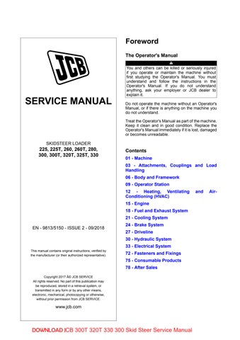
206.
1 Oil feed from main gallery
2 Small transfer gallery 3 Shaft pedestal
Rocker shaft fixing bolt hole
5 Centre rocker shaft drilling 6 Cross drillings
7 Rocker pivot bushes 8 Cross drilling 9 Groove
Lubrication
Oil is fed from the main gallery via a drilling which passes up through the crankcase and the cylinder head to a small transfer gallery under the rocker shaft pedestal. The oversize rocker shaft fixing bolt hole allows oil to pass into a drilling in the centre of
the rocker shaft. Further cross drillings transfer oil to each of the rocker pivot bushes. A cross drilling in each rocker transfers oil to the top of the rocker where it flows by gravity along a groove to the rocker tip.
Check (Condition)
1.Check the rocker shaft and rocker bushings for signs of damage and excessive wear. Measure the rocker shaft diameter and rocker bearing bushes to confirm they are within service limits. Refer to Technical Data. Note: The rocker bearing bushes are not renewable. If a rocker bearing bush is damaged or worn the rocker must be renewed as a complete assembly. Refer to: PIL 15-42.
2.Make sure that all oil-ways and cross drillings in the rocker shaft, rocker arms and pedestals are clear and free from debris. Use an air line to blow through cross drillings.
Remove and Install
Before Removal
1.Make sure that the engine is safe to work on. If the engine has been running, let it cool before you start the service work.
2.Get access to the engine.
3.Disconnect and remove the fuel pipes from the fuel injectors, refer to Fuel pipes (PIL 18-96).
4.Remove the rocker cover, refer to (PIL 15-42).
Remove
1.Remove the rocker shaft fixing bolts. DO NOT withdraw the bolts. Lift the rocker shaft assembly from the cylinder head complete with pedestals still attached. Important: Keep all pedestals and fixing bolts in their original positions.
2.Lift off the bridge pieces from the pairs of inlet and exhaust valves.
3.Withdraw the push rods from the cylinder block.
Before Installation
1.Make sure that all items are clean and free from damage and corrosion. Refer to Check Condition (PIL 15-42).
2.Make sure that all oil-ways and cross drillings in the cylinder head, rocker shaft and pedestals are clear and free from debris. Use an air line to blow through the cross drillings.
Install
1.The installation procedure is the opposite of the removal procedure. Additionally do the following steps.
2.Use a suitable degreasing agent to clean the top of the cylinder head.
3.Install the bridge pieces on to the pairs of inlet and exhaust valves in the cylinder head.
4.Insert the push rods into the cylinder block. Make sure that they engage with the camshaft tappets.
5.Install the rocker shaft assembly into the cylinder head.Makesurethatthepedestalsarelocatedin their original positions. Note the position of the oil feed pedestal and the longer bolt. Make sure that the push rods engage with the tappet adjusters and that the rockers are located over the bridge pieces.
6.Tighten the bolts to the correct torque value.
After Installation
1.Measure and adjust the valve clearances, refer to (PIL 15-30).
Table 68. Torque
Disassemble and Assemble
Before Disassembly
1.Remove the rocker cover. Refer to (PIL 15-42).
2.Remove the rocker assembly. Refer to (PIL 15-42).
Disassemble
1.Lift out the rocker shaft fixing bolts, then slide the pedestals, rockers and wave washers off the rocker shaft as shown. Label the pedestals and rockers to make sure that they are installed in the correct positions on assembly.
2.Check the rocker shaft and rocker bushings for signs of damage and excessive wear. Refer to Check (Condition) (PIL 15-42).
Assemble
1.The assembly procedure is the opposite of the disassemble procedure. Additionally do the following steps.
2.Lubricate the rocker shaft and rocker bearing bushes with clean engine oil.
3.Make sure that the rockers and pedestals are installed in their original positions along the rocker shaft. Note the position of the oil feed pedestal.
4.Insert the rocker shaft fixing bolts to hold the rockers and pedestals loosely in position before fitting the assembly into the cylinder head. Note the position of the longer bolt.
After Assembly
1.Install the rocker assembly. Refer to (PIL 15-42).
2.Install the rocker cover. Refer to (PIL 15-42).
06 - Rocker Cover
Remove and Install
For: JCB Tier 4i /T4F <55kW Engine 4 Cyl .. Page 15-187
For: JCB Tier 2/3 Mech Engine 4 Cyl .. Page 15-188
(For: JCB Tier 4i /T4F <55kW Engine 4 Cyl)
Before Removal
1.Make sure that the engine is safe to work on. If the engine has been running, let it cool before you start the service work.
2.Clean the engine. Refer to Engine - Clean (PIL 15-00).
Remove
1.Get access to the engine.
2.Remove the high pressure fuel pipes. Refer to Fuel Pipes (PIL 18-96).
3.Remove the fuel bleed off fuel pipes. Refer to Fuel Pipes (PIL 18-96).
4.Disconnect the electrical connectors at the fuel injectors. Refer to Fuel Injection (PIL 18-18).
5.Disconnecttheelectricalconnectoratthecoolant temperature sensor. Refer to Engine Sensors (PIL 15-84).
6.Move the electrical harness away from the rocker cover.
7.Remove the bolts and lift the rocker cover from the cylinder head.
8.Discard the gasket.
9.Therockercoverinjectorsealsmustbereplaced. Refer to Injector seals (PIL 18-18).
Install
1.The installation procedure is the opposite of the removal procedure. Additionally do the following steps.
2.Remove all oil and sludge contamination from inside the rocker chamber.
3.Renew the injector seals. Refer to Injector seals (PIL 18-18).
4.Renew the rocker cover gasket.
5.Prevent damage to the seals. Put sleeves/covers on the four injectors. Apply a rubber lubricant to the seals and then install the rocker cover.
6.Tighten the bolts to the correct torque value.
7.Remove the sleeves/covers.
After Installation
1.The high pressure fuel pipes must be replaced with new parts. Refer to Fuel Pipes (PIL 18-96).
2.Start the engine and check for oil and fuel leaks.
Table 69. Torque Values
JCB Tier 2/3 Mech Engine 4 Cyl)
Before Removal
1.Make sure that the engine is safe to work on. If the engine has been running, let it cool before you start the service work.
2.Clean the top of the rocker cover and around the fuel injectors. Refer to Engine - Clean (PIL 15-00).
3.Disconnect and remove the fuel pipes from the injectors. Refer to: PIL 18-96.
3.1.Caps for blanking the open ends of the fuel pipes are supplied with the rocker cover gasket kit.
1 Rocker cover
3 Pipe stub (breather hose)
5 Inlet manifold
7 Injector sleeves/covers
2 Bolts (x6)
4 Turbocharger outlet (Turbocharged engines only) Injector seals
6 Gasket
8 Rocker cover injector seals
Remove
1.Get access to the engine.
2.Disconnect the breather hose from the pipe stub.
3.Disconnect the air hose from the turbocharger outlet and inlet manifold. Remove the hose. (For Turbocharged Engine Only)
4.Remove the bolts and lift the rocker cover from the cylinder head.
5.Discard the gasket.
6.Put the sleeves/covers over the injectors.
7.Therockercoverinjectorsealsmustbereplaced. Refer to Injector seals (PIL 18-18).
Install
1.The installation procedure is the opposite of the removal procedure. Additionally do the following steps.
2.Remove all oil and sludge contamination from inside the rocker chamber.
3.Install new the injector seals. Refer to Injector seals (PIL 18-18).
4.Install new the rocker cover gasket.
5.Prevent damage to the seals. Put sleeves/covers on the four injectors. Apply a rubber lubricant to the seals and then install the rocker cover.
6.Tighten the bolts to the correct torque value.
7.Remove the sleeves/covers.
After Installation
1.Connect the fuel pipes to the injectors. Refer to: PIL 18-96.
2.Start the engine and check for oil and fuel leaks.
Table 70. Torque Values
Nm B 24
21 - Tappet
Remove and Install
For: JCB Tier 4i /T4F <55kW Engine 4 Cyl .. Page 15-193 For: JCB Tier 2/3 Mech Engine 4 Cyl .. Page 15-194
(For: JCB Tier 4i /T4F <55kW Engine 4 Cyl)
Before Removal
1.Drain the oil from the engine.
2.Disconnect and remove the fuel pipes from the injectors. Refer to (PIL 18-96).
3.Remove the rocker cover. Refer to (PIL 15-42).
4.Remove the fuel injection pump. Refer to (PIL 18-18).
5.Remove the rocker assembly and push rods. Refer to (PIL 15-42).
6.Remove the starter motor. Refer to (PIL 15-75).
7.Remove the oil sump. Refer to (PIL 15-45).
8.Remove the flywheel. Refer to (PIL 15-54).
9.Remove the flywheel housing. Refer to (PIL 15-54).
10.Rotate the crankshaft until the camshaft timing pin can be inserted through the gear and into the aligning hole in the rear gear case.
Figure 211.
A Timing pin - camshaft
11.Remove the taper blanking plug and insert the crankshaft locking pin. The camshaft and crankshaftlockingpinsmustbeinpositiontolock the crankshaft and camshaft before removing the camshaft assembly.
212. B C
B Timing pin - crankshaft C Blanking plug
12.Remove the fuel injection pump drive gear. Refer to (PIL 15-51).
Removal
The engine must be inverted. DO NOT attempt to remove the camshaft and its drive gears with the engine upright. The tappets and push rods will fall into the engine and further dismantling will be required to retrieve them.
1.Remove the camshaft timing pin.
2.Carefully withdraw the camshaft and gear assembly from the crankcase. Make sure you fully support the camshaft to prevent the lobes contacting the bearing surfaces in the crankcase. The bearing surfaces can easily be damaged by the sharp hard edges on the cam lobes.
Figure 213.
A Timing pin - camshaft D Camshaft and drive gear
3.Access the tappets through the apertures in the crankcase bedplate next to the crankshaft. Lift out the tappets from the crankcase using a suitable magnetic probe. Label the tappets to ensure replacement in their original positions.
Figure 214.
Installation
1.Lubricate the tappets and tappet bores inside the crankcase with clean engine oil.
2.Insert the tappets in their original positions in the crankcase using a suitable magnetic probe.
3.Lubricate the camshaft bearing journals inside the crankcase with clean engine oil.
4.Carefully insert the camshaft assembly into the crankcase as shown. Support the camshaft preventing the lobes contacting the bearing surfaces in the crankcase. Before meshing the camshaft gear with the crankshaft gear, rotate the camshaft until the timing hole in the gear aligns with the dowel hole in the gear casing. Insert the timing pin to lock the camshaft in this position.
After Installation
1.Note that the fuel injection pump drive gear fixing nut is torque tightened as part of the fuel injection pump replacement procedure. Refer to (PIL 18-18).
2.Do the procedures in Before Removal in reverse order.
E Tappet (8 off) F Magnetic probe
Inspection
1.Inspect the camshaft gear teeth for signs of damage or excessive wear.
2.Inspect the cam lobes for signs of excessive wear, scoring or pitting.
3.Inspect the cam bearing surfaces for signs of excessive wear, or scoring. Check that the dimensions are within service limits.
4.Inspect the cam bearing surfaces inside the crankcase for signs of excessive wear, or scoring. Check that the dimensions are within service limits.
5.Inspect the bearing surfaces of the tappets for signs of excessive wear or damage. Check that the dimensions are within service limits.
6.Inspect the tappet bores inside the crankcase for signs of excessive wear or damage. Check that the dimensions are within service limits.
7.If any of the camshaft bearings or lobes are worn or damaged then the relative oil feed galleries in the crankcase and camshaft may be blocked. Make sure all oil ways are clear and free from debris.
(For: JCB Tier 2/3 Mech Engine 4 Cyl)
Special Tools
Description Part No. Qty. Crankshaft / Camshaft Timing Pin (444/448/672 Engine)
892/01148 1
Before Removal
1.Drain the oil from the engine.
2.Disconnect and remove the fuel pipes from the injectors.
Refer to: PIL 18-96.
3.Remove the rocker cover.
Refer to: PIL 15-42-06.
4.Remove the fuel injection pump. Refer to: PIL 18-18-15.
5.Remove the rocker assembly and push rods. Refer to: PIL 15-42-09.
6.Remove the starter motor.
Refer to: PIL 15-75-00.
7.Remove the oil sump.
Refer to: PIL 15-45-00.
8.Remove the flywheel. Refer to: PIL 15-54-00.
9.Remove the flywheel housing. Refer to: PIL 15-54-03.
10.Rotate the crankshaft until the camshaft timing pin can be inserted through the gear and into the aligning hole in the rear gear case.
Special Tool: Crankshaft / Camshaft Timing Pin (444/448/672 Engine) (Qty.: 1)
Figure 215.
A Timing pin - camshaft
11.Remove the taper blanking plug and insert crankshaft locking pin. The camshaft and crankshaftlockingpinsmustbeinpositiontolock the crankshaft and camshaft before removing the camshaft assembly.
Special Tool: Crankshaft / Camshaft Timing Pin (444/448/672 Engine) (Qty.: 1)
Figure 216.
B Timing pin- crankshaft C Blanking plug
12.Remove the fuel injection pump drive gear. Refer to: PIL 15-51-09.
Removal
The engine must be inverted. DO NOT attempt to remove the camshaft and its drive gears with the engine upright. The tappets and push rods will fall into the engine and further dismantling will be required to retrieve them.
1.Remove the camshaft timing pin.
Special Tool: Crankshaft / Camshaft Timing Pin (444/448/672 Engine) (Qty.: 1)
2.Carefully withdraw the camshaft and gear assembly from the crankcase. Make sure you fully support the camshaft to prevent the lobes contacting the bearing surfaces in the crankcase. The bearing surfaces can easily be damaged by the sharp hard edges on the cam lobes.
Figure 217.
A Timing pin - camshaft D Camshaft and drive gear
3.Access the tappets through the apertures in the crankcase bedplate next to the crankshaft. Lift out the tappets from the crankcase using a suitable magnetic probe. Label the tappets to ensure replacement in their original positions.
218.
E Tappet (8 off) F Magnetic probe
Inspection
1.Inspect the camshaft gear teeth for signs of damage or excessive wear.
2.Inspect the cam lobes for signs of excessive wear, scoring or pitting.
3.Inspect the cam bearing surfaces for signs of excessive wear, or scoring. Check that the dimensions are within service limits.
4.Inspect the cam bearing surfaces inside the crankcase for signs of excessive wear, or scoring. Check that the dimensions are within service limits.
5.Inspect the bearing surfaces of the tappets for signs of excessive wear or damage. Check that the dimensions are within service limits.
6.Inspect the tappet bores inside the crankcase for signs of excessive wear or damage. Check that the dimensions are within service limits.
7.If any of the camshaft bearings or lobes are worn or damaged then the relative oil feed galleries in the cylinder block and camshaft may be blocked. Make sure all oil ways are clear and free from debris.
Installation
1.Lubricate the tappets and tappet bores inside the crankcase with clean engine oil.
2.Insert the tappets in their original positions in the crankcase using a suitable magnetic probe.
3.Lubricate the camshaft bearing journals inside the crankcase with clean engine oil.
4.Carefully insert the camshaft assembly into the crankcase as shown. Support the camshaft preventing the lobes contacting the bearing surfaces in the crankcase. Before meshing the camshaft gear with the crankshaft gear, rotate the camshaft until the timing hole in the gear aligns with the dowel hole in the gear casing. Insert the camshaft timing pin to lock the camshaft in this position.
After Installation
1.Note that the fuel injection pump drive gear fixing nut is torque tightened as part of the fuel injection pump replacement procedure.
Refer to: PIL 18-18-15.
2.In reverse order, carry out the procedures in Before Removal.
Engine 42 - Rocker and Fittings
- Tappet Cover
24 - Tappet Cover
Remove and Install
It is not necessary to remove the tappet covers unless a new rocker cover is to be installed. It is necessary to remove the tappet covers to measure and adjust the valve clearances. Refer to ValveAdjust, Valve Clearances (PIL 15-30).
Remove
1.Make sure that the engine is safe to work on. If the engine has been running, let it cool before you start the service work.
2.Get access to the engine.
3.Clean the tappet covers and the adjacent areas of the rocker cover. Refer to Engine - Clean. Important: Make sure that the screws do not fall into the engine.
4.Remove the tappet cover screws.
5.Keep the screws away from the engine.
6.Useascrewdriverintheslottoremovethetappet covers. Make sure that dirt or debris does not fall into the engine.
219.
A Screws
B Tappet covers
C Slot
D Rocker cover
E Tappet cover seals
Install
1.The installation procedure is the opposite of the removal procedure. Additionally do the following steps.
2.Inspect the tappet cover seals for signs of damage. Replace any damaged seals.
3.Install the tappet covers. Tighten the screws to the correct torque value.
Table 71. Torque Values

If there is no response to click on the link above, please download the PDF document first and then clickonit.
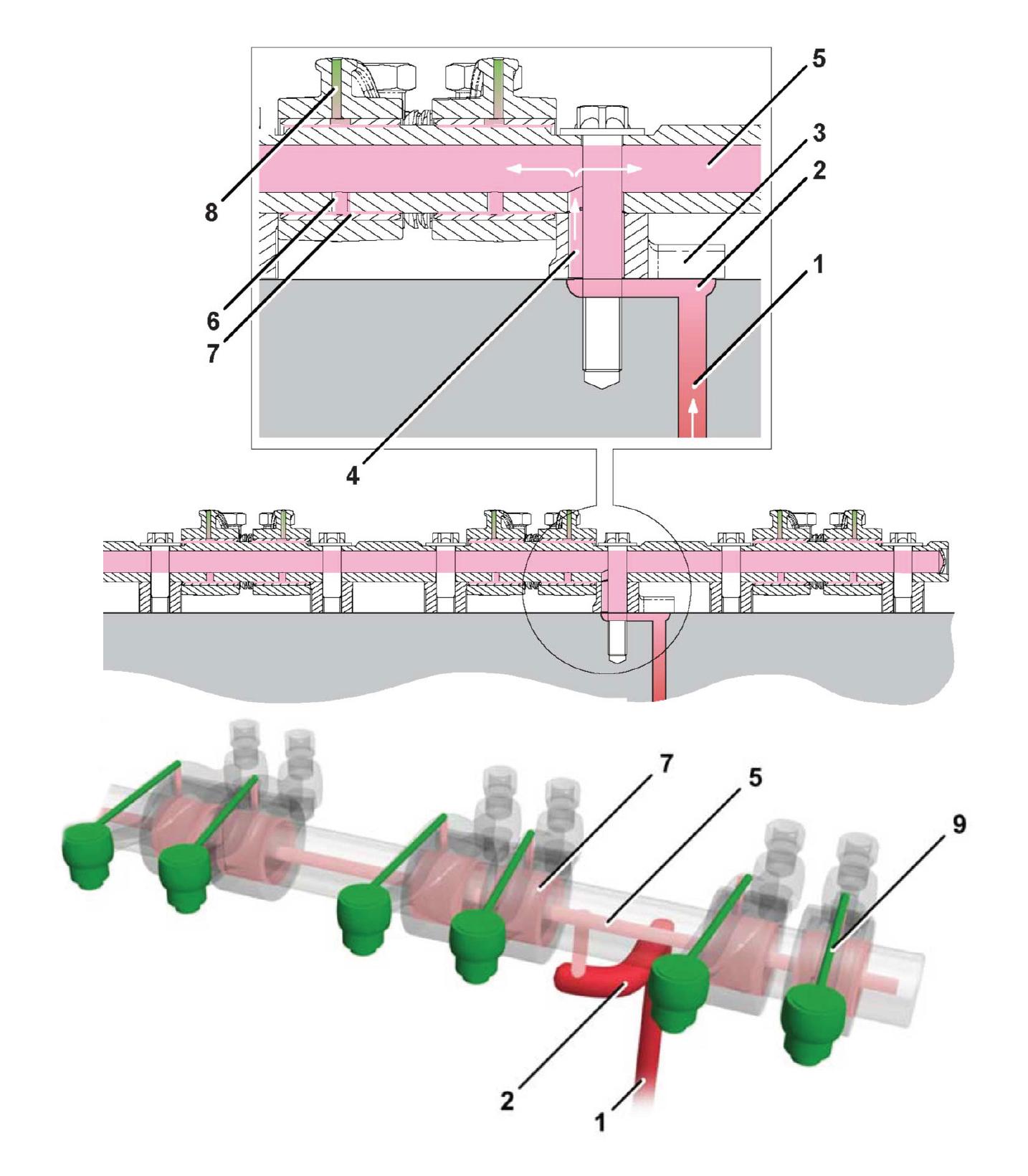
PTO (Power Take-Off) idler gear bearing/ timing case - high pressure oil feed
Main high pressure oil feed gallery (crankcase)
Rocker assembly - high pressure oil feed
External high pressure oil feed connection (crankcase) - Turbocharger (if installed)
Remove and Install
Special Tools
Description Part No. Qty.
Template for Sealant Oil Sump - Pressed
Oil Sump Location Dowel
Template for Sealant Oil Sump (Cast)
Consumables
892/01149 1
892/01150 2
892/12354 1
Description Part No. Size Clear Silicone Sealant 4102/0901 0.31 L
Before Removal
1.Make sure that the engine is safe to work on. If the engine has been running, make sure the engine has cooled sufficiently before you start.
2.Drain the engine oil.
Removal
1.Remove the fixing bolts and remove the oil sump from the engine. The oil sump may be difficult to remove due to adhesion of sealing compound. If necessary, carefully lever the mating flanges apart. Do not use excessive force, the oil sump could be damaged. Be sure to retrieve the oil pick up seal.
2.Use a gasket removal compound, carefully remove all traces of sealing compound from the oil sump and engine mating faces. Do not allow the sealing compound to enter the engine.
3.Use a suitable degreasing agent to thoroughly clean the oil sump.
Installation
1.Lightly smear the new oil pick up seal with oil and install into the bedplate as shown.
Figure 222.
3 Oil pick up seal
2.Install the two guide pins at the oil sump screw holes in the engine.
Special Tool: Oil Sump Location Dowel (Qty.: 2)
3.Use the fixing bolts to locate the template to the oil sump mating face. Make sure that the templateisthecorrectwayround(notethatholes are on different centres).
Special Tool: Template for Sealant Oil Sump (Cast) (Qty.: 1)
Special Tool: Template for Sealant Oil SumpPressed (Qty.: 1)
4.Apply a bead of sealing compound around the oil sump flange using the inside edge of the template as a guide as shown. Note the beads around holes.
Length/Dimension/Distance: 4mm
Consumable: Clear Silicone Sealant
5.Carefully remove the template without smudging the sealant beads.
6.Apply a bead of sealant so as to join the sealant beads around holes with the bead around the oil sump flange.
Length/Dimension/Distance: 4mm
7.After applying the sealing compound, the oil sump must be installed and the bolts torque tightened within Duration: 5min
Figure 223. X X
S Hole T Hole T2 Guide pins X 4mm Bead of sealant
8.Position the oil sump with the suction tube outlet aligned with the oil pump inlet port on the engine. Takecarenottodamagetheoilpickupsealwhen youinstalltheoilsump.Damagetothesealcould cause a drop in oil pressure and subsequently damage to the engine.
9.Locate the oil sump on the guide pins on the engine. Avoid smudging the sealant beads. DO NOT remove the guide pins until sufficient bolts have been installed to secure the oil sump.
10.Installtheboltsandtightentheboltstothecorrect torque value. Note that the bolts are not installed at 6 positions.
Figure 224.
2 Bolts Y No bolts to be installed at this position (x6)