Volumes 1,


2, 2, 4, 5 & 6

Series
Series 20
Series 30
Part 1 — Engine Systems
Paû 2 — Fuel Systems
NOTE
Some of the information in this manual is reprinted from the previous Repair Manual as the service information contained herein is equally applicable to the new Series 10 and Series 30 models. First check the appropriate section to see if the model has a specific chapter. If no model is shown, the model numbers have been updated as follows:
From -

Ford 2600 -
Ford 3600 -
Ford 4100 -
Ford 4600 -
Ford 5600 -
Ford 6600 -
Ford 6700 -
Ford 7600 -
Ford 7700 -
To
Ford 2610
Ford 3610, 2810, 3230, or 3430
Ford 4110, 3910, or 3930
Ford 4610, 4630
Ford 5610
Ford 6610
Ford 6710
Ford 7610, 7810*
Ford 7710, 8210**
Tractor models 7810 and 8210 have been added to this manual. Both tractors utilize the 401 CID engine from the TW Series tractors. The engine repair information from the TW Repair Manual is reprinted at the end of Section 1 for your benefit.
* The Model 7810 tractor is based on the Model 7610 tractor with the exception of a modified, derated TW-5 engine. Repair procedures for the 7610 should be followed except for the engine proper. Refer to the material for engine repair. One important exception must be noted. The Model 7810 engine oil pump location and drive is the same as the Model 7610.
”* The Model 8210 tractor is based on the Model 7710 tractor with exception of a derated TW-5 engine. Repair procedures for the 7710 should be followed except for the engine proper. Refer to the TW-5 material for engine repair.
Both Models 7810 and 8210 utilize the same inline fuel injection pump used on the TW-5 tractor. Fuel delivery specifications vary. Any repair or adjustment must be carried out by an authorized fuel injection repair service.
Ford New Holland, Inc.
FOREWORD
This Service Manual provides information for the correct servicing and overhaul of the Ford Series 10 and Series 30 3- and 4 cylinder agricultural tractors, including derivative models, and is an essential publication for all service personnel carrying out repairs or maintenance on these tractors. We reCommend that this manual be available for reference at all times.
The Service Manual consists of fourteen Parts contained in six volumes. A Table of Contents is included in each volume which lists all fourteen Parts and the volume where each can be found. Five Parts have been reprinted from the prior Repair Manual as the service information in these five Parts is still valid for the new model series. A page giving a model cross reference is included in the front of each volume to advise the reader to transpose model numbers.
All Parts are subdivided into Chapters which convey information on general operating principles. detailed inspection and overhaul procedures and, where appliCable, specifics on troubleshooting, special tools and specifications. Any reference in this manual to right, left, rear, front, top or bottom is as viewed from the operator's seat.
The information contained herein was correct at the time of going to print but Ford New Holland, Inc. policy is one of continuous improvement and the right to change prices, specifications, equipment or design at anytime without notice is reserved. All data in this manual is subject to production variations and the illustrations do not necessarily depict tractors to standard build specifications.
Ford New Holland, Inc.

PRODUCTION DATE CODES AND SERIAL NUMBERS
Ford Tractors have a series identification plate located under the radiator filler access cover for Ford 6710 and 7710 models and under the right-hand hood panel for all other models. Whenever effectingrepair or overhaul the relevant series information should be noted andused whenreferring toService Bulletinsand/or the Parts Catalogue.
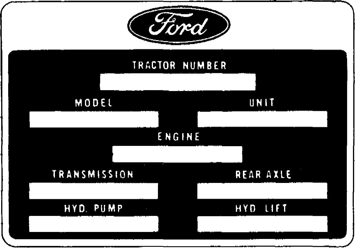
TRACTOR SERIES IDENTIFICATION PLATE
This plate is stamped with the following information:
e TRACTOR NUMBER — Serial number prefixed by the letter ’A’, ’B’ or ’C’.

e MODEL Production model code.
e UNIT — Production unit date code.
e ENGINE — Serial number and engine production date code.
KEY TO PRODUCTION DATECODES
e TRANSMISSION— Transmission production date code.
e REAR AXLE — Rear axle production date code.

e HYD. PUMP — Hydraulic pump production date code.
e HYD. LIFT Hydraulic power lift production date code.
First Number YEAR First Letter MONTH Second Number DAY OF MONTH Second Letter PRODUCTION SHIFT 1—1981 2 1982 3 1983 4 1984 5 1985 A Jan. G-JuIy B Feb. H-Aug. C March J Sept. D April K Oct. E May L Nov. F—June M—Dec. 01/28/29/30/31 A Midnight B Day C Afternoon Example of Production Unit Date Code 1 0 3 B Year of Final Assembly (1981) Month of Year (November) Day of Month (Third) ShiftPeriod (Day) (iV)
FUEL I ECTION PU DATE CODES


The fuel injection pumps carry an identification plate with the pump type number, serial number andmanufacturer'sproductiondate code.Thedatecodecanbeidentified by referenceto the following chart.
MONTH CODE YEAR CODE 1981 82 1983 86 January N A 1981 Y A B D February O B March P C 1982 April R D May S E 1983 June T F July U G 1984 August V H September W J 1985 October X K November December Y Z L M 1986
Pump Type Number Manufacturer's Serial Number Month of Year (March) Year (1982) (v) 3 3 4 2 F 7 7 0 R 2 2 5 6 4 P
Example of Fuel Injection Pump Identification Plate
SAFETY ECAUTIONS
Practically all Service work involves the need to drive the tractor. The Operators Manual, supplied with each tractor, contains detailed safety precautions relating to Driving, Operating and Servicing that tractor. These precautions are as applicable to the service technician as they are to the operator, and should be read, understood and practised by all personnel.
Prior to undertaking any maintenance, repair, overhaul, dismantling or re-assembly operations, whether withinaworkshopfacilityorout “in the field”, consideration shouldbegiventofactorsthatmayhavean effectuponSafety.Notonlyuponthemechanic car•vingoutthework,butalsouponbystanders.

PERSONALCONSlDERATIONS
• The wrong clothes or carelessness in dress can cause accidents. Check to see that you are suitably clothed.
Some jobs require special protective equipment.
• Eye Protection
The smallest eye injury may cause loss of vision. Injury can be avoided by wearing eye protection when engaged in chiselling, grinding, discing, welding, painting, etc.
• Breathing Protection
Fumes, dust and paint spray are unpleasant and harmful. These can be avoided by wearing respiratory proteGtion.
• Hearing Protection
Loud noise may damage your hearing and the greater the exposure the worse the damage. If you feel the noise excessive wear ear protection.
• Hand Protection
It is advisable to use a protective cream before work to prevent irritation and skin contamination. After work clean your hands with soap and water. Solvents such as white spirit, paraffin, etc., may harm the skin.
• Foot Protection
Substantial or protective footwear with reinforced toe-caps will protect your feetfrom falling objects. Additionally oil-resistant soleswillhelptoavoid slipping.
• Special Clothing
For certain work it may be necessary to wear flame- or acid- resistant clothing.
• Avoidinjury through incorrect handling of components. Make sure you arecapable of liftingtheobject.If indoubtgethelp.

EOUIPMENT CONSIDERATIONS
• Machine Guards
Before using any machine, check to ensure that the machine guards are in position and serviceable. These guards not only prevent parts of the body or clothing coming in contact with the moving parts of the machine, but also ward off objects that might fly off the machine and cause injury.
• Lifting Appliances
Always ensure that lifting equipment, such as chains, slings, lifting brackets, hooks and eyes are thoroughly checked before use. If in doubt, select stronger equipment than is necessary.
Never stand under a suspended load or raised implement.
• Compressed Air
The pressure from a compressed air line is often as high as 100Ibf/in * (6.9 bar) (7 kgf/cm 2). It is perfectly safe if used correctly. Any misuse may cause injury.
Never use compressed air to blow dust, swarf, dirt, etc., away from your work area unless the correct type of nozzle is fitted.
Compressedairisnotacleaningagent,itwillonlymovedust,etc.,fromoneplacetoanother.Look around beforo using an air hose as bystanders, may get grit into their eyes, ears or skin.
(vi)
• Hand Tools
Many cuts, abrasions and injuries are caused by defective or improvised tools. Never use the wrong tool for the job, as this generally leads either to some injury, or to a poor job.
Never use
Ahammer withaloosehead orsplithandle.

Spanners or wrenches withsplayedor worn jaws. Spanners or files as hammers; or drills, clevis pins or bolts as punches.
For removing or replacing hardened pins use a copper or brass drift rather than a hammer.
For dismantling, overhaul and re-assembly of major and sub components, always use the Special Service Tools recommended.
These willreduce thework effort, labour timeandtherepair cost.
Always keep tools clean and in good working order.
• Electricity
Electricity has become so familiar in day to day usage, that it's potentially dangerous properties are often overlooked. Misuse of electrical equipment can endanger life.
Before using any electrical equipment particularly portable appliances make a visual check to ensure that the cable is not worn or frayed and that the plugs, sockets, etc., are intact. Make sure you know where the nearest isolating switch for your equipment is located.
GENERAL CONSIDERATIONS
• Solvents
Use only cleaning fluids and solvents that are known to be safe. Certain types of fluids can cause damage to components such as seals, etc., and can cause skin irritation. Solvents should be checked that they are suitable not only for the cleaning of components and individual parts, but also that they do not affect the personal safety of the user.
• Housekeeping
Many injuries result from tripping or slipping over, or on, objects or material left lying around by a careless worker. Prevent theseaccidents fromoccurring. If younoticeahazard, don'tignoreit removeit.
A clean, hazard-free place of work improves the surroundings and daily environment for everybody.
• Fire
Fire has no respect for persons or property. The destruction that a fire can cause is not always fully realised. Everyone must be constantly on guard.
Extinguish matches/cigars/cigarettes, etc., before throwing them away. Work cleanly, disposing of waste material into proper containers. Locate the fire extinguishers and find out how to operate them. Do not panic warn those near and raise the alarm. Do not allow or use an open flame near the tractor fuel tank, battery or component parts.
• First Aid
In the type of work that mechanics are engaged in, dirt, grease, fine dusts, etc., all settle upon the skin andclothing.If acut,abrasion orburnisdisregarded itmaybefoundthatasepticcondition hasformed withina short time. What appears atfirst to betrivial couldbecome painful and injurious. It onlytakes a fewminutestohavea fresh cutdressed, but itwilltakelonger if youneglect it. Make sureyouknow where the First Aidbox is located.
• Cleanliness
Cleanliness of the tractor hydraulic system is essential for optimum performance. When carrying out service and repairs plug all hose ends and component connections to prevent dirt entry.
Clean the exterior of all components before carrying out any form of repair. Dirt and abrasive dust can reduce the efficiency and working life of a component and lead to costly replacement. Use of a high pressure washer or steam cleaner is recommended.
OPERATIONAL CONSIDERATIONS
• Stoptheengine, if at allpossible, beforeperforming anyservice.
• Place a warning sign on tractors which, due to service or overhaul, would be dangerous to start. Disconnect thebattery leads ifleaving suchaunitunattended.
• Donot attempt tostart the engine while standing beside the tractor or attempt to by-pass the safety start switch.
• Avoid prolonged running of the engine in a closed building or in an area with inadequate ventilation as exhaust fumes are highly toxic.
• Always turntheradiator cap tothefirst stop, toallow pressureinthesystem todissipate when the coolant is hot.
• Never work beneath a tractor which is on soft ground. Always take the unit to an area which has a hard working surface concrete for preference.
• If it is found necessary to raise the tractor for ease of servicing or repair, ensure that safe and stable supports are installed, beneath axle housings, casings, etc., before commencing work.
• Certain repair or overhaul procedures may necessitate "separating the tractor”, either at the engine/front transmission or front transmission/rear transmission connections. These operations are simplified by the use of the Tractor Splitting Kit/Stands. Should this equipment not be available, then every consideration must be given to stability, balance and weight of the components, especially if a cab is installed.
• Usefootsteps or working platforms when servicing thoseareas ofa tractor thatarenotwithin easy reach.
• Before loosening any hoses or tubes connecting implements to remote control valves, etc., switch off the engine, remove all residual pressure in the lines by moving operating levers several times. This will remove the danger of personal injury by oil spurt.
• Prior to pressure testing, ensure all hoses and connectors, not only of the tractor, but also those of the test equipment, are in good condition and tightly secured. Pressure readings must be taken with the gauges specified. The correct procedure should be rigidly observed to prevent damage to the system or the equipment, and to eliminate the possibility of personal injury.
• When equipment or implements are required to be attached to the hydraulic linkage, either for testing purposes or for transportation, then "position control” should be engaged.
• Always lower equipment tothe groundwhen leaving the tractor.
• If high lift attachments are fitted to a tractor beware of overhead power, electric or telephone cables when travelling. Drop attachment near to ground level to increase stability and minimise risks.
• Donotparkorattempttoservice atractor onanincline. If unavoidable, takeextra careandblock all wheels.
• Observe recommended precautions as indicated in this Repair Manual Part 13 when dismantling the air conditioning system as escaping refrigerant can cause frostbite.
• Prior to removing wheels and tyres from a tractor, check to determine whether additional ballast(liquid or weights) has been added. Seek assistance and use suitable equipment to support the weight of the wheel assembly.
• Wheninflatingtyresbewareof overinflation constantlycheckthepressure. Over inflation cancause tyreburst andresult inpersonal injury.

Safety precautions are very seldom the figment of someone's imagination. They are the result of sad experience, where most likely someone has paid dearly through personal injury.
Heedtheseprecautions andyouwillprotect yourself accordingly. Disregard themandyoumayduplicatethe sad experience of others.
Safetyis everybody's responsibility.


CONTENTS Part 1 Engine Systems 1 Part 2 Fuel Systems ................... 1 Pai13 Electrical Systems Chapter 1 to Chapter 8 ................... Part 3 Electrical Systems Vol. 2A Chapter 9 to Chapter 14 ............................. Pai1 CIutches o o a o o u o • a • o a e a • a o o e • • • • • e • • • • e • • o a e e e • e • • • • e Part 5 — Transmission Systems Part 6 Power Take-Off ...................................... Pai17 Rear Axle & Brakes .................................. a 8 a e g g g g g g Part 9 — Steering Systems Part 10 Front Axle .......................................... Part 11 Safety Cabs & PlaNorms ............................ Part 12 Separating the Tractor .............................. Part 13 Accessories & General .............................. Part 14 Model Derivatives ................................... Vol. 2B Vol. 3 Vol. 3 Vol. 3 Vol. 4 Vol. 4 Vol. 4 Vol. 5 Vol. 5 Vol. 6 Vol. 6 Vol. 6

PART I SYSTE
Chapter 1
DIESEL ENGINES
Chapter
Chapter 4
TR BLE SHOOTING, ›PECIFICATI JS AND SPEC TOOLS


Section A. DIESEL ENGINE DESCRIPTION AND OPERATION B. DIESEL ENGINE OVER HAUL Chapter 2 COOLING SYSTEM Page 1 4 Section Page A. COOLING SYSTEM DESCRIPTION AND OPERATION 1 B. COOLING SYSTEM OVERHAU L 2
3 GASOLINE ENGINES Section Page A. GASOLINE ENGINE DESCRIPTION AND OPERATION 1 B. GASOLINE ENGINE OVER HAUL 1
Secton A. TROUBLE SHOOTING B. SPECIFICATIONS C. SPECIAL TOOLS Page 1 6 18 (i)

PART I SYST
Chapter 1 DIESEL ENGINES
Section

A. DIESEL ENGINE DESCRIPTION AND OPERATION
B. DIESEL ENGINE OVERHAUL
Page 1 4
A. DIESEL ENGINE DESCRIPTION AND OPERATION


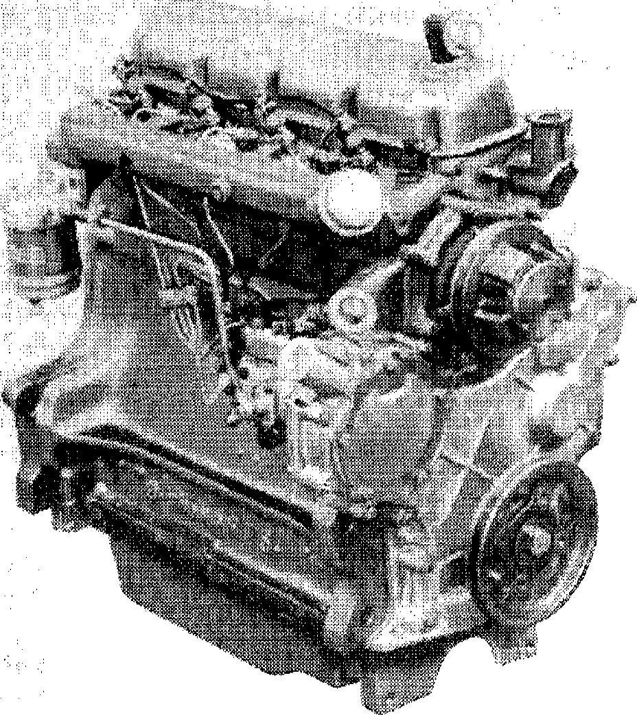
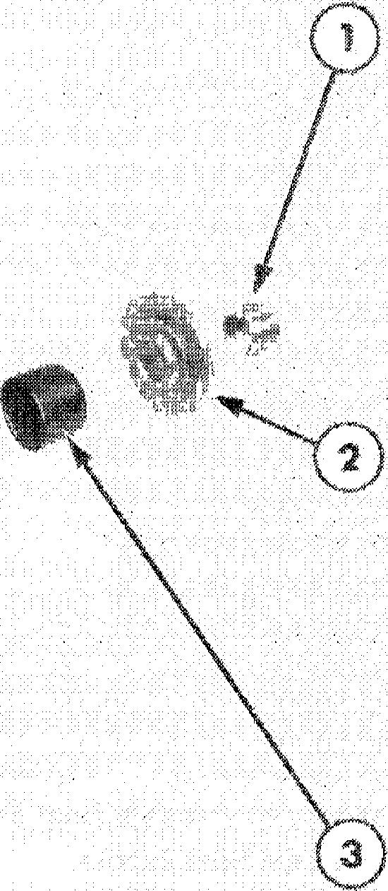
This Chapter describes the overhaul and The engines feature cross flow cylinder repair of the Ford Tractor direct injection heads with the inlet and exhaust manifolds diesel engines. The Chapter covers the 3 and on opposite sides of the head. The combus4-cylinder engines, the latter in both the tion chamber is formed in the crown of the normally aspirated and turbocharged forms, piston which has three compression and Figures 1, 2, 3 and 4. one oil control ring, all located above the piston pin.
All the engines are of similar design and hence service procedures are basically common throughout the range. The major difference The cylinder head assembly incorporates between the engines is that the 4-cylinder units the valves, valve springs and spring retainers. are fitted with a dynamic engine balancer and Valve guides are an integral part of the the Ford 7610 and 7710 engines are cylinder head with replaceable valve seats turbocharged. pressed into the valve ports.
The following chart shows the 3 and 4 cylinder diesel engine options available.
Model Ford 2610 Ford 3610 Ford 4110 Ford 4610 Ford. 5610 Ford 6610 & 6710 Ford 7610 & 7710 (Turbocharged) No. of Cylinders 3 3 3 3 4 4 4 Bore 4.2in. (106.7 mm) 4.4in. (111.8 mml 4.4in. (111.8 mm) 4.4in. (111.8 mm) 4.4 in. ( 111.8 mm) 4.4in. (111.8 mm) 4.4in. (111.8 mm) Stroke 4.2in. (106.7 mmT 4.2in. (106.7 mm) 4.4in. (111.8 mm) 4.4in. (111.8 mm) 4.2in. (106.7 mm) 4.4in. (111.8 mm) 4.4in. (111.8 mm) Displacement 175 in° (2868cm 3) 192in° (314/ cm’) 201in° (3294 cm 3) 201 in" t3294cm*) 256in* (4195cm*) 268in* (4393cm*) 268 in* (4393cm*) 1
The crankshaft is supported in the cylinder Front and rear crankshaft oil sealing is block by four main bearings for the 3-cylinder effected by one piece, single lip type seals. engine and five main bearings for the 4-cylinder engine. Crankshaft end thrust is suppressed by a thrust bearing located on The crankshaft rear main bearing carrier the second main bearing of the 3-cylinder block is sealed by two composition type engine and the centre (third) main bearing side seals and a gasket positioned between of the 4-cylinder engine. the block and the engine rear adaptor plate.
ENGINE
PART 1
SYSTEMS
Figure 1
Figure 3
3-Cylinder Diesel Engine with Distributor Type 4-Cylinder Diesel Engine with In-Line Type Fuel Fuel Injection Pump Injection Pump
Figure 2
Figure 4
2
4-Cylinder Diesel Engine with Distributor Type 4 Cylinder Turbocharged Diesel Engine with Fuel Injection Pump In- Line Type Fuel Injection Pump
A crankshaft driven dynamic balancer, installed on the 4-cylinder engines, counteracts out-of balance forces and thereby reduces engine vibration. The balancer housing is bolted to the bottom of the cylinder block and contains two meshing gears which are driven and timed from a gear machined on the crankshaft.
The piston connecting rods are of ’I’ section and for the turbocharged engines a centrally drilled hole facilitates both pressure lubrica tion of the piston pin bushing and cooling of the piston crown.
The fully floating piston pin is retained in the piston by two snap rings.
The camshaft drive gear bushing is pressure lubricated through a drilled passage from the front main bearing. The gear has small oil passages machined on both sides which allow the oil to escape.
The timing gears are lubricated by oil from the cam followed chamber and the pressure lubricated camshaft drive gear bushing.
On the 4 cylinder engines, the dynamic balancer is Iubricated through a drilled passage from the cylinder block intermediate thrust bearing web to the balancer housing. Oil flows through the balancer housing to the drilled balancer gear shafts and onto the bushings in the balancer gears.
LUBRICATION SYSTEM
Lubrication of the engine is maintained by a rotor type oil pump mounted at the base of the engine block. The oil pump is driven from the camshaft and draws oil from the engine sump through a wire mesh screen.
A spring loaded relief valve in the pump body limits the pressure in the system by directing excess oilback to the intake side of thepump.
Oil passes from the pump to an external, throw-away, spin on type filter incorporating a relief valve which permits oil to be bypassed, if filter blockage occurs, and so ensures engine lubrication at all times.
Oil flows from the filter to the main oil gallery which runs the length of the cylinder block and intersects the camshaft follower chambers.
The main gallery also supplies oil to the crankshaft main bearings and to the connecting rod journals via drillings in the crankshaft. Drilled passages from each main bearing direct oil to the camshaft bearings.
Cylinder walls, pistons and piston pins are splash lubricated by the connecting rods and rotating Crankshaft.
An intermittent flow of oil is directed to the valve rocker arm shaft assembly via a drilled passage in the cylinder block located vertically above the No. 1 camshaft bearing. This drilling aligns with a corresponding hole in the cylinder head. As the camshaft turns, holes in the camshaft and camshaft bearing align and a regulated stream of oil is directed to the cylinder head and on up the rocker arm shaft support bolt to the rocker shaft. The oil flows from the shaft through drilled holes in each rocker arm bushing to lubricate both ends of the arms. Excess oil flows down the push rods and assists in lubricating the cam followers before draining back into the sump through cored openings in the block.
For the Ford 6610, 6710, 7610 and 7710 engines, a water-to-oil type oil cooler, located in the base of the radiator is connected into the lubrication system mdin oil gallery and cools a prcportion of the circulating oil. A restrictor at the oil outlet limits the flow tothe cooler and maintains internal lubrication at low engine speeds. Return oil from the cooler is fed back to the engine sump via a pipe tapped into the skirt of the cylinder block.
CHAPTER 1
B. ENGINE- OVERHAUL
CYLINDER HEAD, VALVES AND RELATED PARTS REMOVAL
NOTE: The cylinder head can be removed with the engine installed in the tractor.
1. Disconnect the battery.
Ford 2610, 3610, 4110, 4610, 5610, 6610 and 7610:
• Remove the battery and battery tray.
« Remove the vertical muffler (where fitted).
2. Drain the radiator and cylinder block.
3. Shut off the heater hose taps then disconnect and plug the heater hoses.
4. Remove the radiator top hose.
5. Shut off the main fuel tank tap.
Ford 2610, 3610, 4110, 4610, 5610, 6610 and 7610:
e Remove the hood panel assembly.
• Remove theradiator shell support.
» Remove the two bolts securing the fuel tank to the hood rear support.
• Disconnect the horizontal type exhaust pipe (where fitted) from the exhaust manifold.
« Disconnect the air inlet hose at the clamp at the intake manifold.
Ford 6710and 7710:
• Remove the main fuel tank. See ”FUEL SYSTEMS” - -Part 2.
6. Disconnect and remove the rocker cover ventilation tube.
Ford 7610and 7710:
» Remove the turbocharger assembly. See ”FUEL SYSTEMS” Part 2.
7. Disconnect the alternator, oil pressure, temperature sender, air cleaner restriction indicator and cold start wiring harness connections (where fitted).
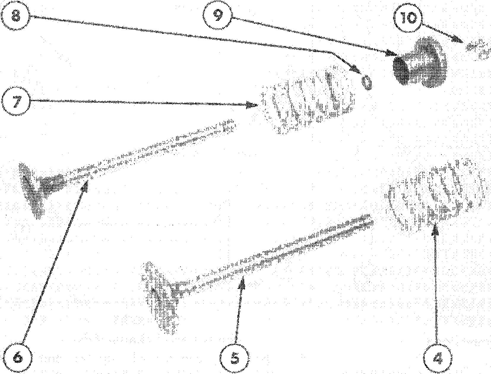
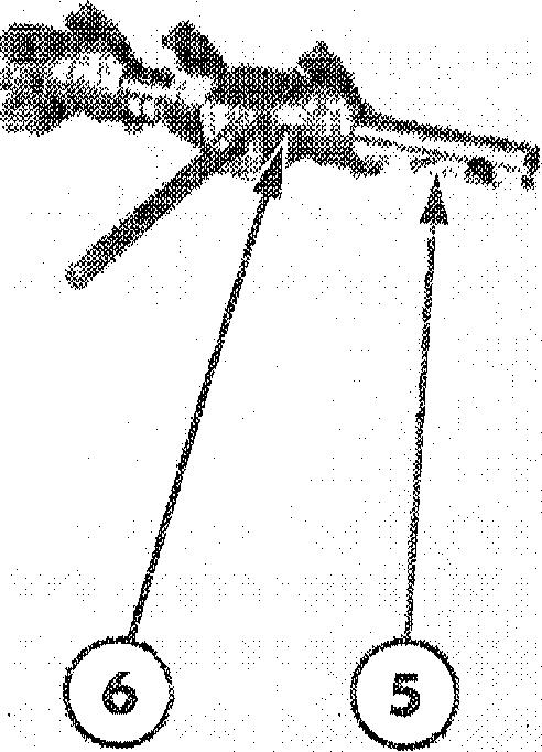
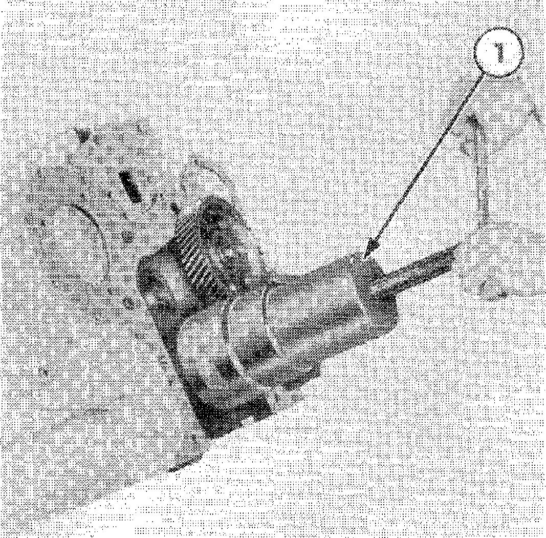
8. Remove the alternator and guard (where fitted), Figure 5.
Ford 2610, 3610, 4110, 4610, 5610, 6610 and 6710:
» Remove the vertical type exhaust pipe and bracket (where fitted).
PART 1 ENGINE SYSTEMS
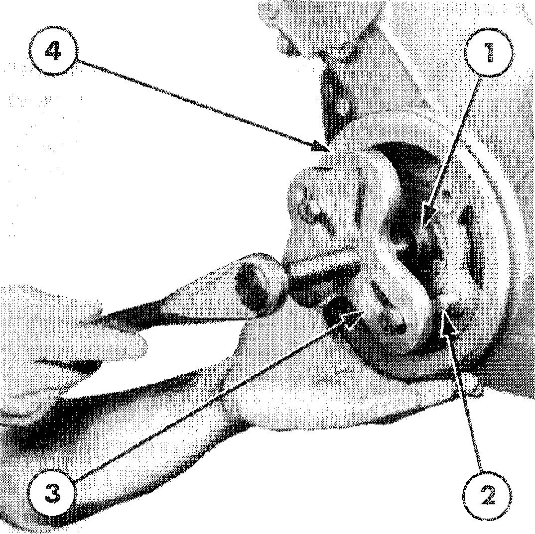
Figure 5 4-Cylinder Engine with Rocker Arm Cover Removed
1. Intake Manifold
2. Injection Tubes
3. Leak-Off Tubes
4. Fuel Filter
S. Rocket Shaft Assembly
6. Exhaust Manifold
7. Rocket Shaft Retaining Bolts
8. Tab Washer 9. Alternator
10. Cold Start Tube
4
9. Bend the lock tabs back, withdraw the attaching bolts and remove the exhaust manifold and gasket
10. Disconnect the cold start equipment (where fitted).
11. Remove the injector lines from the fuel injection pump and the injectors. Cap the exposed openings in the pump, injectors and tube ends.
12. Disconnect the fuel lines and remove the fuel filter(s) from the inlet manifold.
13. Withdraw the retaining bolts and lockwashers and remove the inlet manifold and gasket.
Ford 6710and 7710:
e Place a block under the hood frame rear support and remove the four bolts attaching the support to the rear of the cylinder head.
14. Withdraw the securing bolts and remove the rocker arm cover and gasket from the cylinder head.
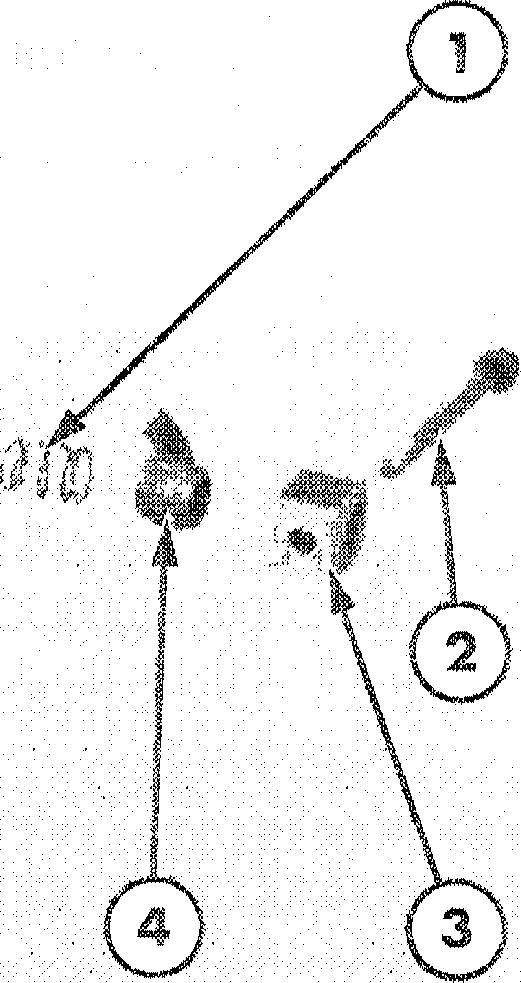
15. Hold the leak-off pipe at each injector and carefully disconnect the fuel injector leakoff pipes. Clean the area surrounding the fuel injectors then remove the bolts and carefully withdraw the fuel injectors and washers, Figure 6.
16, Check the push rods for straightness by rotating the rods with the valve closed and identify any bent rods.
6
FuelInjectorRemoved
1. Fuel Injector Assembly
2. Fuel Injector Mounting Bolts
3. Copper Washer
4. CorkWasher
17. Loosen the rocket shaft retaining bolts, which also serve as cylinder head bolts, evenly and alternately. Remove the rocker shaft assembly.
NOTE: Leave the bolts in the rocket shaft supports during removal as they retain the supports on the shaft.
18. Remove the push rods and place in a numbered rack.
19. Remove the remaining cylinder head bolts and washers working inwards from the ends to the centre of the head.
20. Lift the cylinder head from the block. If necessary lever the head off on the pads provided, taking care not to damage the cylinder head or block faces.
1
CHAPTER
Figure
5
PART 1 ENGINE SYSTEMS
DISASSEMBLY THERMOSTAT:
1. Remove the coolant outlet connection
INSPECTION AND REPAIR
CYLINDER HEAD :
1. Scrape all gasket surfaces clean then and the thermostat and gasket, Figure 7. wash the cylinder head in a suitable solvent and thoroughly dry with a lint free cloth or compressed air.
CYLINDER HEAD:
2. Clean the head and remove carbon deposits from around the valve heads.
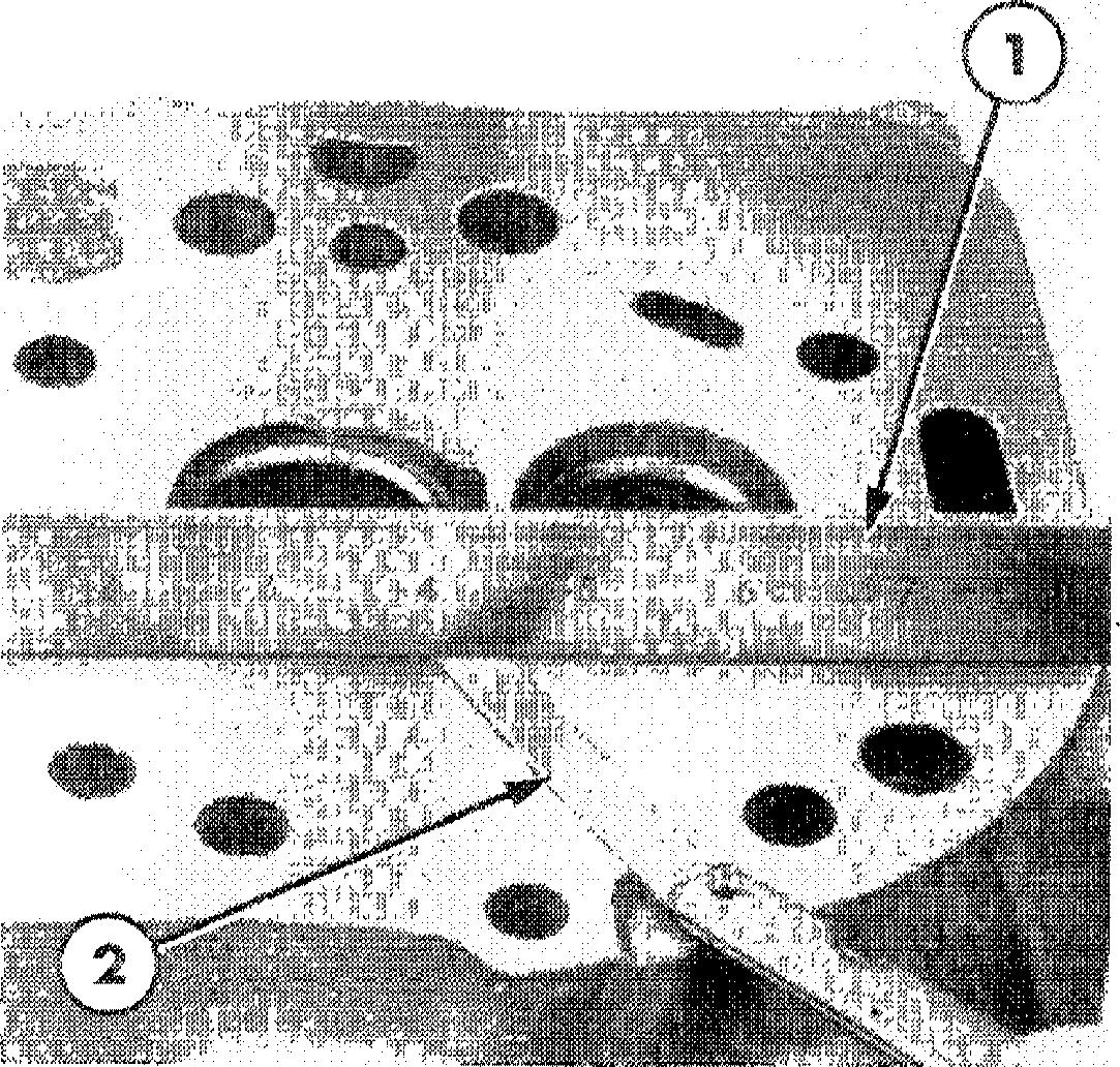
3. Using a valve spring compressor, Figure 8, remove the retainer locks, spring retainers/rotators, springs and seals from each valve, Figure 9.
2. lnspect the cylinder head for damage and, if necessary, remove nicks and burrs from the gasket faces using a suitable abrasive. Ensure all traces of abrasive material are removed atter repair.
4. Withdraw the valves and place in a 3‘ numbered rack together with the valve rotators (where fitted).
ROCKER SHAFT ASSEMBLY:
5. Remove the cylinder head bolts which pass through the rocker shaft supports and slide the rocker shaft components from the shaft, Figure 10.
Use a straight edge to check the flatness of the cylinder head in all directions, Figure 11. For flatness requirement see ‘Specifications" Chapter 4.
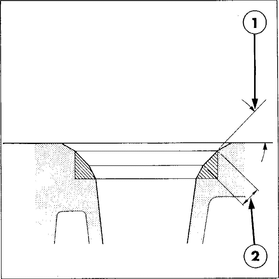
NOTE : If the cylinder head exceeds the flatness specification it may be skimmed providing the depth from the lower face of the valve insert to the cylinder head face is not less than 0 064 iii. (I 63 mm).
Coolant Outlet and Thermostat Removal 1. Cylinder Head 2. Gasket 3. Thermostat
Coolant Outlet Connection
Figure7
4.
6
Figure
8 ValveRemoval 1. Valve Spring Compressor 2. Retainer Locks 3. Valve Spring 4. Cylinder Head
CHAPTER 1
Fig ure 9
Valve Assembly Components
1. Intake Valve Spring Retainer Lock
6. Exhaust Valve
2. Intake Valve Spring Retainer
3. Intake Valve Seal
4. Intake Valve Spring
S. Intake Valve
7. Exhaust Valve Spring
8. Exhaust Valve Seal
9. Exhaust Valve Spring Retainer
10. Exhaust Valve Spring Retainer Locks
1. Spring
Figure 10
Figure 11
Rocker Shaft Disassembled
Measuring Cylinder Head Flatness
4. Rocker Arm 1. Straight Edge
2. Retaining Bolt
3. Shaft Support
S. Shaft 2. Feeler Gauge
7
6. Spacer
Valve Seat Dimensions
1 Valve Seat Angle: 45°00’ 45o30’ for all Valve Seats except Intake Valve Seat on Turbocharged Engines to be 30O00’ 30°30’
2. Valve Seat Width
Intake 0 080 0 102 in (2-032-2 590 mm)
Exhaust 0•084-0 106 in (2 133-2 692 mm)
4 After skimming the head, check whether any cylinder head bolts are bottoming by mounting the cylinder head on the block without a gasket and without any of the pistons at T.D.C. Install all the bolts finger tight and ensure the rocker shaft supports and flat washers arefitted with the long bolts.If a 0 010 in. (0 25 mm) feeler gauge can be inserted under the bolt head then the bolts are botioming and the cylinder block thread must be increased in depth. Use a in.x13 UNC 2A thread tap.
VALVE SEATS :
5. Examine the valve seat inserts and reface if pitted butreplace if damaged. If necessary, install an oversize insert by machining the seat counterbore in the cylinder head, see ‘Specifications
Chapter 4. The insert must be chilled in dry-ice prior to installation.
13
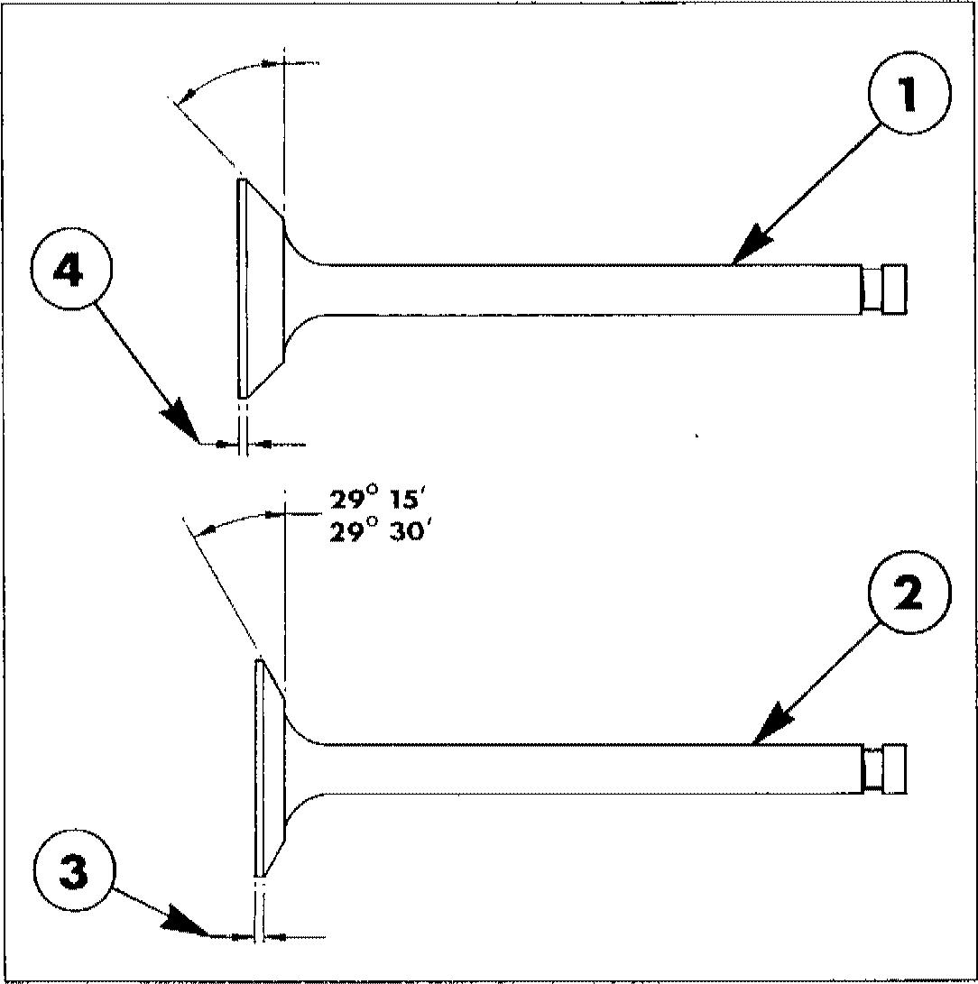
Intake and Exhaust Valves
1. Exhaust Valves for all Engines and Intake Valves for Normally Aspirated Engines
2. Intake Valves for Turbo- Charged Engines
3. Dimension after Refacing: 0 062 in. (1 58 mm) Mininnum
4. Dimension after Relating: O 031 in. (0 79 mm) Minimum

NOTE: Valve seat inserts of O 010 in. (O 25 mm) and O 020 in. (O ! mm) oversize on diameter ore sometimes installed in c yhnder heeds in production. Needs fitted with oversize /oserfs ore stamped 0 on the exhaust manifold side 0S 05 in line with the valve seat concerned
When replacing exhaust valve seat inserts ensure the replacement inserts are of the correct type as the size and material specification varies for the different engine types.
6. Check the width of the valve seat inserts and, if necessary, reface by grinding to the dimensions shown in Figure 12.
NOTE : Pefacinp of the va/ve seat should alwaysbeco-ordinatedwithrefacinpofthe valve to ensure a compression tipht ill.
PART 1 ENGINE SYSTEMS
Figure 1"y
Figure
8 44“ 30’
VALVES :
7. Examine the valve face and, if pitted, replace or reface by grinding to the dimension shown in Figure 13. Before refacing the valve, ensure the valve stem is not bent or worn and check the valve seat run-out, measured at rightangles to the seat, does not exceed a total of 0 0015 in. (0 038 mm).
IMPORTANT: The finished valve seat should contact the centre of the valve face. Usinp the relaxed or new valve, check the seat usinp Prussian Blue. Rotate the valve with a light pressure and if the blue is transferred to the middle of the valve face, the contact is correct.
Measuring Valve Guide
1. Telescopic Gauge
2. Valve Guide
VALVE GUI$›ES:
8. Using a telescopic gauge and micrometer, measure the valve to guide clearance, Figure 14. If the clearance exceeds the specified limits, see ”Specifications” Chapter 4, ream the valve guide to fit the next oversize valve.
• 0 003 in. (0 076 mm) Oversize Reamer and Standard Diameter Pilot
• 0 015in.(0 38mm) Oversize Reamer and 0 003in. (0076mm) Oversize Pilot
NOTE : Production cylinder heads may have one or more 0 0f5 in. (0 38 mm) oversize valve guides and valves installed. Such cylinder heads have IS or VOIS OS stamped on the exhaust manifold side of the head opposite the valve(s) concerned.
« 0 030in.(0 76mm) Oversize Reamer and 0015in.(038mm) Oversize Pilot.
9. Use Kit No. FT.6202 or 2136 to ream out the valve guide to accept an oversize valve. The kit contains three reamer and pilot combinations as follows:
When going from a standard valve stem toanoversize always usetheseamers in sequence. After reaming a valve guide, always check the valve seating and reface if necessary.
CHAPTER 1
Figure 14
VALVE SPRIhIGS :
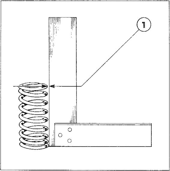
10. Replace worn or damaged valve springs. Check for squareness and reject if out-of-squareness exceeds 0 06 in. (1 5 mm), Figure 15. Check the free length and loaded length of each valve spring, see ’Specifications” Chapter 4. Ensure the valve spring retainer locks are in good condition and the exhaust valve rotators are not binding or worn.
THERMOSTAT:
13. For inspection and repair of the coolant outlet or thermostat, see ”Cooling System Chapter 2.
RE-ASSEM BLY
CYLINDER HEAD :
ROCKER SHAFT ASSEIVIBLY:
11. Examine the rocker arm for wear or damage. Check the adjusting screw threads and replace if damaged. Inspect the rocker arm locating springs and spacers for damage. Check the rocker arm-to-shaft clearances and replace if beyond specified limits, see “Specifications” Chapter 4.
12. Clean the shaft in a suitable solvent and thoroughly dry with compressed air ensur.ng the oil passages are free from obstruction.
1. Insert each valve in the guide bore from which it was removed and lap in position to ensure an even seat around the valve. Withdraw the valve and ensure removal of all traces of lapping compound.
2. Use a valve spring compressor to reassemble the valves, valve springs, retainers and retainer locks. For the exhaust valves install a new sealing rinp in the second groove from the top of the valve stern.
NOTE: Turbocharged engines hove no seols fitted to the intake valves.
PART1 EI\IGINE SYSB“EMS
Figure 15
Checking Valve Spring Squareness
1. Maximum Out-of-Squareness 0‘06 in. (1 5 mm)
1. Notch
Figure 16
Rocl‹er Shaft Installation
10
THER MOSTAT :
3, Install the thermostat (spring end towards the head), coolant outlet and a new gasket.
ROCKER SHAFT ASSEMBLY :
4 Coat all components with engine oil and position the notch on the front of the rocker shaft upwards to correctly locate the oil holes, Figure 16.
INSTALLATION
Installation of the cylinder head and related components follows the removal procedure in reverse. On installation observe the following requirements:
o Install new cylinder head, intake and exhaust manifold gaskets.
e Ensure washers are installed under the heads of the cylinder head retaining bolts. Tighten the cylinder head bolts in the sequence shown in Figure 17, and progressively in three steps as follows:


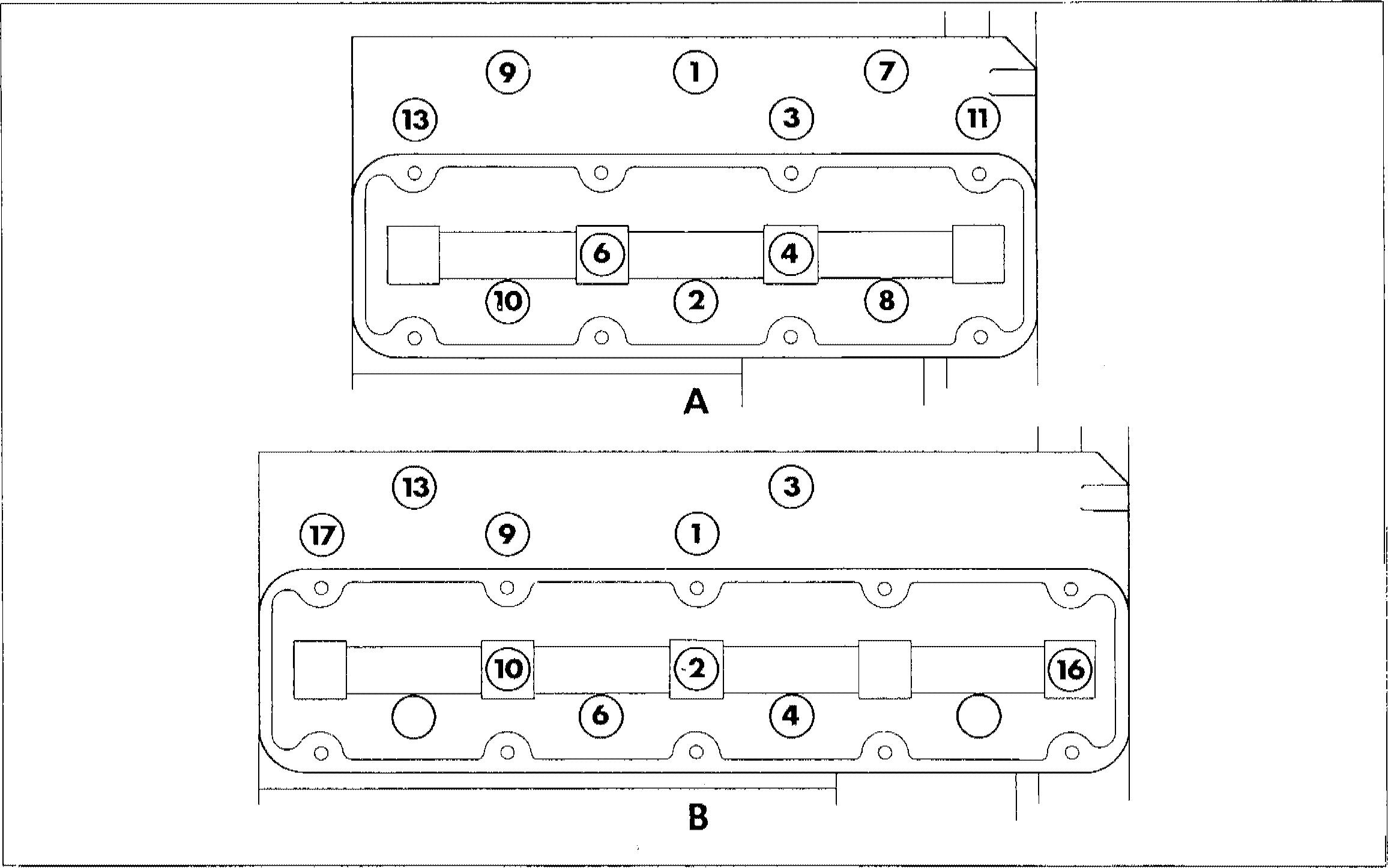
(i) Torque to 90Ibf.ft. (122 Nm)

s. Start the assembly from the shaft rear end by securing a rocker arm support with a long bolt. Ensure the notch on the support is positioned to the right of the shaft when looking forward. Proceed to installaspacer,rocker arm,spring,rocker
(ii) 1"orque to 100 Ibf.ft. (135 Nm)
(iii) Torque to110Ibf.ft. (149 Nm) arm and support. Repeat the procedure NOTE: The cylinder head bolts should be until complete. torqued only when the engine is co/d
1
CHAPTER
A. 3-Cylinder Engines
Figure 17
Cylinder Head Bolt Tightening Sequence 11
14 12
B. 4- Cylinder Engines
• Rotate the engine and set the valve lash. ENGINE FRONT COVER AND TIMING Figure 18. See “Specifications” Chapter GEARS 4.
REMOVAL
• Install the injectors with new seat washers NOTE: The engine front cover and timinp and cork seals. gears can only be serviced after removing the radiator and front axle. See “SEPARATING THE TRACTOR” Par7 12.
« Install the injector lines and leak-off pipe with new washers.
NOTE: Hold the leak-offplestic tube securely 1 to preventpivofting when tightening the banjo liftingboltstothecorrecttorque.See “Specifixations” Chapter 4.
• Usenewlocktabsfortheexhaustmanifold retaining bolts and bend the tabs to effect retention.
Drain the engine oil and remove the oil pan.
2. Remove the fan drive belt and withdraw the bolt and washer from the centre of the crankshaft pulley.
e Tighten all nuts and bolts to the 3. Using Puller No. 518 or 9539 and Shaft specified torques. See “Specifications” Protector No. 625-A or 9212. remove the Chapter 4. crankshaft pulley, Figure 19.
ENGINE
PART 1
SYSTEMS
Figure 18
Setting Valve Lash
1. Adjuster Screw
2. Feeler Gauge
Figure 19
Crankshaft Pulley Removal
1. Shaft Protector No.625-A or 9212
2. in.x14UNC Bolt
3. Puller No. 518or 9539
4. Crankshaft Pulley
2
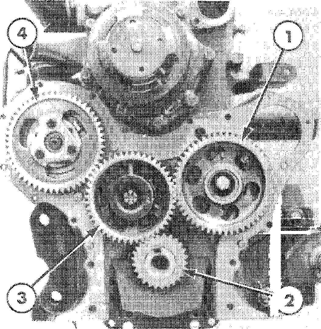
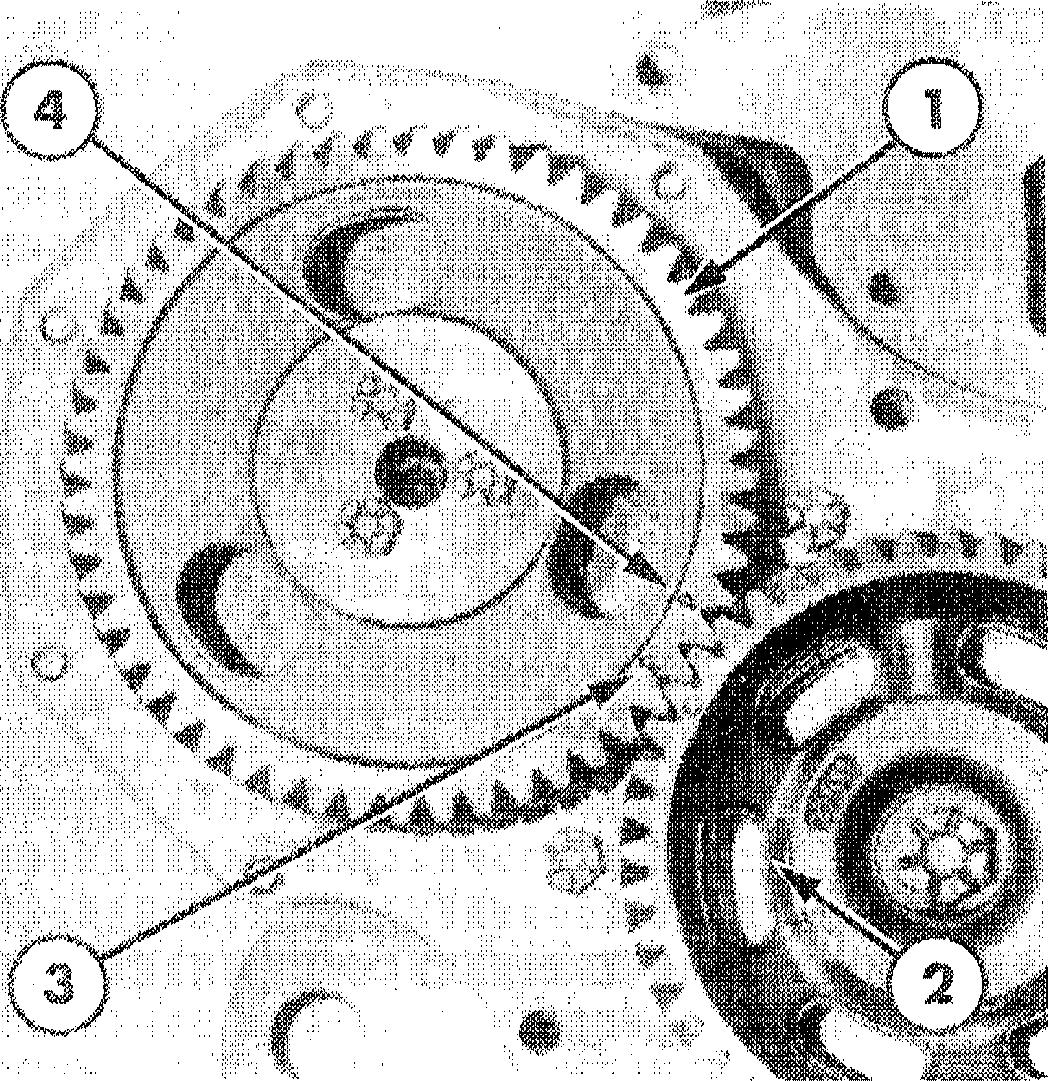
Timing Gears
1. Camshaft Gear
2. Crankshaft Gear
3. Camshaft Drive Gear
4. Injection Pump DriveGear
Measuring Timing Gear Backlash
1. Camshaft Gear
2. Oil Slinger (Reference Only)
3. Feeler Gauge
4. Camshaft Drive Gear
4. Remove the power steering pump where fitted, see “STEERING SYSTEMS" Part 9.
s. Withdraw the retaining bolts then remove thefront cover and gasket. Remove the oil slinger.
6. Before removing the timing gears, Figure 20, use a dial indicator or feeler gauges, to measure the backlash between each set of mating gears, Figure 21. Rotate the gears and check the backlash at four equidistant points on the gears. Renew the gears if the backlash exceeds the specified limits, see”Specifications" Chapter 4.
7. Pry the camshaft gear away from the thrust plate and using a dial indicator or feeler gauges, measure the clearance, Figure 22. Install a new camshaft thrust plate if the camshaft end play exceeds the specified limits, see “Specifications" Chapter 4.
Measuring Camshaft End Play
1. Screwdriver
2. Feeler Gauge
3. Camshaft Gear
4. Thrust Plate
CHAPTER 1
Figure 20
Figure 21
Figure 22
Fi9ure 23
Crankshaft Gear Removal
1.Puller ToolNo. CPT.6040-B or 2134
8. Remove the fuel injection pump drive gear, camshaft drive gear and adapter and the camshaft gear. Use Tool No. CPT.6040-B or 2134 to remove the crankshaft gear, Figure 23.
NOTE: The crankshaft pear should only be removed if it shows signs of wear.
Figure 24
Crankshaft Gear Installation
1. ReplacerToolNo. CT.6069-A or2134and ToolNo.CT.6069-1 or1237
INSTALLATION
1. Install the spacer, key and the camshaft gear then re-check the camshaft end play
2. Locate the key then use Tool No. CT.6069-A or2134andCT.6fB9-1or1237 toinstall thecrankshaft gear, Figure 24.
INSPECTION AND REPAIR
1. Wash the gears and adapter in a suitable solvent and dry with a clean lint free cloth or compressed air.
2. Examine the gear teeth for wear, burrs or scratches. Any minor burrs or scratches may be removed with a fine abrasive; ensure such parts are thoroughly washed before re-assembly.
3. Ensure the camshaft drive gear adapter oil passage is free from obstruction and the drive gear bushing is not damaged.
4. Check the key and keyway in the end of both the camshaft and crankshaft for damage. Replace the keys if necessary.
3. Position No. 1 piston at Top Dead Centre and install the camshaft drive gear and adapter with the timing marks aligned with those of the other gears.
Tighten the bolt to the specified torque and re-check the backlash between the gears.
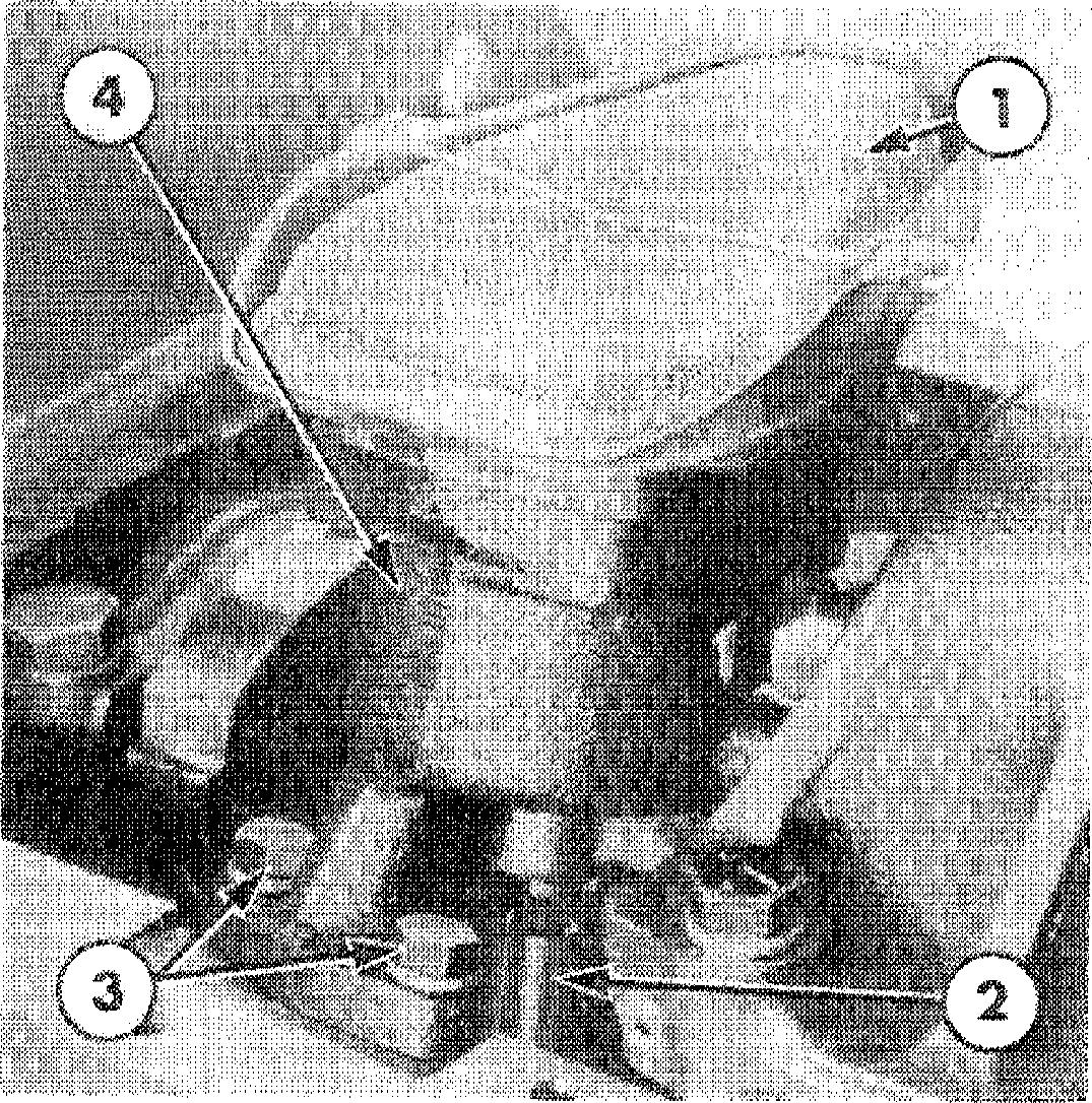
4. Assemble the fuel injection pump tothe engine front plate. Check No. 1 piston is atT.D.C. and install the injection pump drive gear with the timing mark aligned with that of the camshaft drive gear, Figure 25.
PART 1 ENGINE SYSTEMS
14
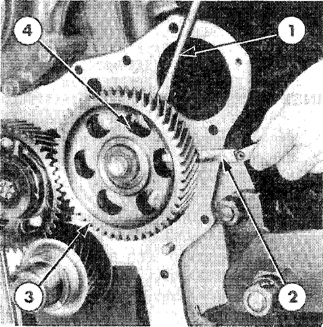
AligningtheTimingGears
1. Camshaft Gear
2. Crankshaft Gear
3. Camshaft Drive Gear
4. Injection Pump DriveGear
Rotary IDistributor) TypeFuelInjection Pump Drive Gear toCamshak Drive Gear Timing
1. Pump DriveGear
2. Camshaft Drive Gear
3. 3-Cylinder Timing Mark
4. 4-Cylinder Timing Mark
NOTE: A// engines with a rotary (distributor) 7. type fuel injection pump have a common fuel injection pump drive gear. This gear features two timinp marks iden‹“ified by numerals
‘3’ and ‘4’ for 3 and 4-*Y!inder engines respectively, Figure 26. When installing the pump drive gear, ensure the appropriate 3 or 4-cylinder timinp mark aligns with the
camshaft drive gear timing mark.
Position a new gasket on the engine front plate and install the front cover ensuring the cover aligns with the dowel pins. Tighten the bolts to the specified torque.
5. Install a new dust seal in the front cover. Lubricate the oil seal with petroleum jelly and use a 630-S or 9210 adaptor to press the seal into the front cover.
8. Lubricate the crankshaft pulley spacer and slide over the key. Replace the pulley hub and tap onto the crankshaft. Tighten the securing bolt to the specified torque, see "Specifications" Chapter 4.
9. Install the oil pan with a new gasket and tighten the bolts to the specified torque, see "Specifications" Chapter 4.
6. Locate the oil slinger onto the crankshaft with the dished face outwards.
10. Refill the engine with the correct grade and quantity of oil,see "Specifications" Chapter 4.
CHAPTER 1
Figure 25
Figure 26
15
OIL PAN SUMP REMOVAL
NOTE: The oi/ pan sump can be removed with the enpine installed in the tractor
1. Drain the engine oil and remove the oil level indicator.
Ford 2610, 3610and 4110:
• Withdraw the retaining bolts and remove the oil pan sump.
Ford 4610:
• Support the front transmission.
e Remove the hood.
« Disconnect the radiator shell support, slacken the engine to front support bolts leaving the nuts flush or partly disengaged from the end of the bolts.
• Ease the front support and radiator assembly forward to allow the front sump bolts and the sump to be removed.
Ford 5610, dd10and7610:
The sump can be removed by replacing the cylinder block to front support bolts one at a time with 8 in. (200 mm) long bolts. These bolts allow the front support and radiator assembly to be eased forward approximately 1 5 in. (38 mm) to facilitate removal of the sump front bolts.
« Disconnect the enpine oil cooler tubes on the turbocharged enpine.
NOTE : Usinp this procedure it should not be necessary to disconnect the radiator hoses. power steering or hydraulic oil cooler tubes where fitted. However. care must be taken fo ensure no components are unduly stressed.
Ford 6710and7710:
The sump can be removed by replacing the cylinder block to front support bolts one at a time with 8 in. (200 mm) long bolts as for the Ford 5610, 6610 and 7610 models.
• Support the front transmission with a jack and the front support with a hoist or crane.
« Remove the hood, side panels and radiator grilles.
« Securely support the front end of the fuel tank and disconnect the hood frame rails from the radiator support.
e Disconnect the engine oil cooler tubes on the turbocharged engine.
« Separate the hydrostatic steering tubes at the front of the enpine and cap the exposed ends.
• Move the front axle support and radiator assembly forward to facilitate removal of the sump front bolts.
» Remove the sump retaining bolts and the two oil pan to transmission case attaching bolts then lower the sump
WARNING : Due to the weiphf of the cast ironsump.exercise preat care onremoval.
INSPECTION AND REPAIR
1. Scrape all gasket material from the gasket surface then wash the oil pan sump in a suitable solvent and dry with a clean lint free cloth or compressed air.
2. Inspect the sump for cracks, damaged drain plug threads or distorted gasket surface.
PART 1 ENGINE SYSTEMS
16
1. Filter Screen
2. Intermediate Shaft
3. OilPumpRetaining Bolts
4. Oil Pump
lNSTALLATlON
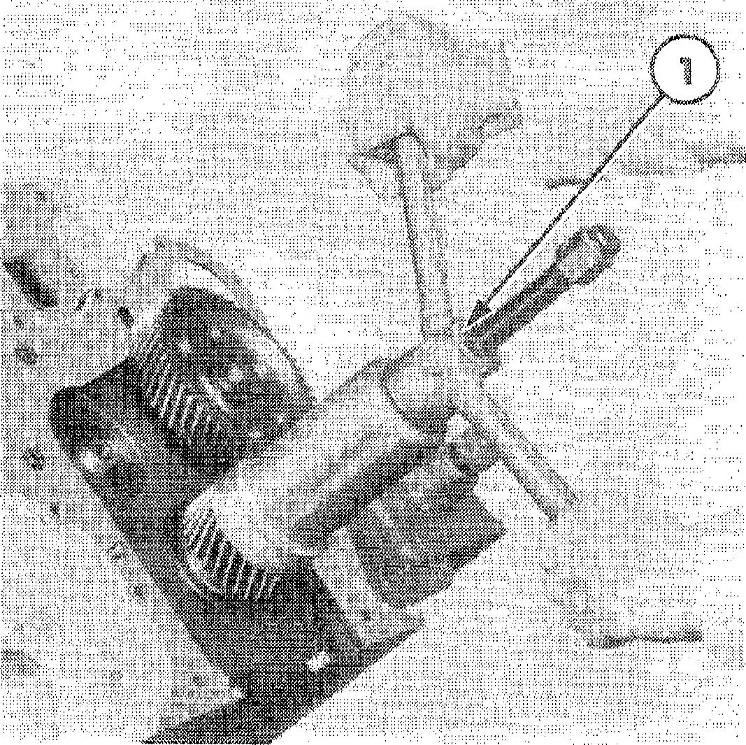
Oil Pump Drive Gear Removal
1. Retaining Bolt
2. Proofmeter Driveshaft Adapter
3. Oil Pump Drive Shaft and Gear Assembly
4. Driveshaft Adapter Mounting Base
Installation of the oil pan sump follows the REMOVAL removal procedure in reverse. Oninstallation observe the following requirements.
1. Remuve the oil pan sump as previously described in this Chapter.
e Ensure the gasket surfaces on the oil pan and block are clean.
e Install a new gasket and apply a thin film of sealer to the gasket, front cover
2. Remove the oil pump with the filter and oil pan. screen, Figure 27. Withdraw the intermediate shaft.
« Position the oil pan and install a bolt finger tight at each corner.
e Install the remaining bolts, tighten the rear bolts first, then tighten from the middle outward in each direction to the specified torque, see "Specifications" Chapter4.
• Fill theengine withthe correct grade and quantity of oil, see "Specifications" Chapter 4.
• Operate theengine and check for oilleaks.
3. Disconnect the proofmeter drive cable from the driveshaft adapter and remove the engine oil filter.
4. Slacken the retaining bolt then withdraw the driveshaft adapter assembly and the oil pump drive gear, Figure 28.
CHAPTER 1
Figure 27
OilPumpandFilterScreen
Figure 28
OIL PUMP
17