
Document Title: Function Group: Information Type: Date:
Engine, description 200 Service Information 2014/12/23
Profile: EXC, EC360C L [GB]
Engine, description
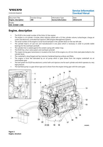
The D12D is the model number of the Volvo 12 liter engine.
The engine is a 6-cylinder, 4-stroke, direct injection diesel with a 12 liter cylinder volume, turbocharger, charge air cooler and electronic controlled fuel injection, EMS (Engine Management System).
The serial number of the engine is to be found stamped in the cylinder block on the rear left side.
The cylinder head is of cast iron and manufactured in one piece which is necessary in order to provide stable bearings for the overhead camshaft.
The cylinder liner is sealed against the coolant casing with rubber rings.
The D12D has a four-valve system and overhead camshaft.
The engine timing gear transmission is located at the front of the engine on a 10 mm thick steel plate bolted to the cylinder block.
The crankshaft is drop forged and has induction hardened bearing surfaces and fillets.
The engine is force fed lubricated by an oil pump which is gear driven from the engine crankshaft via an intermediate gear
The fuel system for D12D has electronic control with unit injectors one for each cylinder and which operate at a very high pressure.
The fuel feed pump is a gear driven type and is driven from the engine timing gear with the same gear.
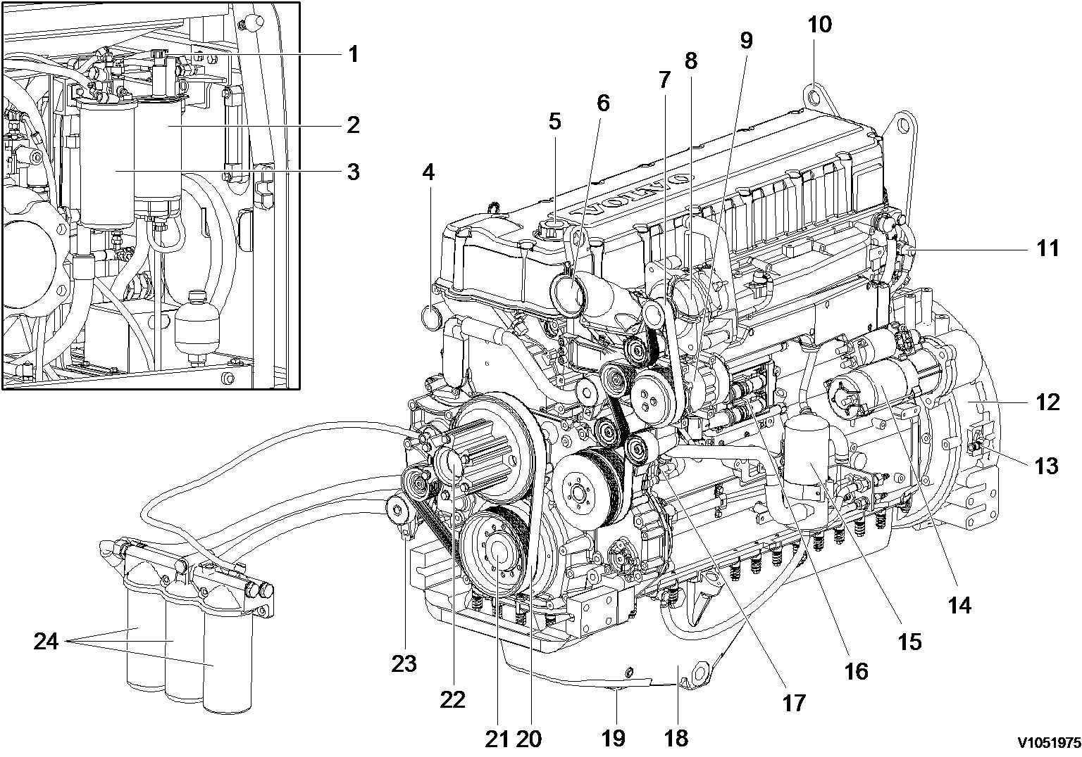
Figure 1
Engine, structure
Document Title: Function Group: Information Type: Date: Engine, identification 200 Service Information 2014/12/23
Profile: EXC, EC360C L [GB]
Engine, identification
Identification plate
The engine model, serial number and performance data are stamped on an identification plate which is attached on the cylinder head cover. The engine model designation and serial number must be indicated when ordering spare parts.

Document Title: Function Group: Information Type:Date: Engine, removing 210 Service Information 2014/12/23
Profile: EXC, EC360C L [GB]
Engine, removing
Op nbr210-070
9998257 Lifting tool
9998547 Lifting device
WARNING
Risk of burns -stop the diesel engine and allow it to cool down before starting any work.
WARNING
Removal of residual pressure from the circuit must be done prior to any maintenance.
NOTE!
Cable ties and clamps that secure hoses and electrical wiring must be removed and then replaced when installing.
1.Place the machine in the service position B. See091 Service positions
2.Turn off the battery disconnect switch.
3.Loosen two screws and connect hose (1). and then drain the hydraulic oil into a suitable collectioncontainer.
4.Drain the coolant in a collection container.
5.Remove under cover (1).
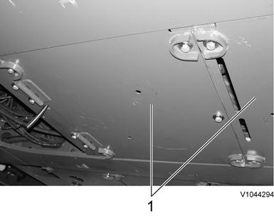
Figure2
Removal, under cover
6.Remove silencer hood (1).
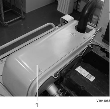
Figure3
Removal, silencer hood
7.Remove screws (1) and open radiator hood (2).
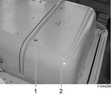
Figure4
Opening, radiator hood
8.Remove the rear cover of the engine hood.
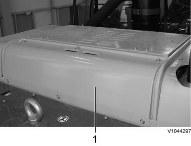
Figure5
Removal, cover
9.Open the engine hood and remove the cowl mounting screws.
10.Remove cowl (1) using a lifting device.
11.Disconnect wire harness connector (2), hoses (3), and remove expansion tank (1) with the bracket.
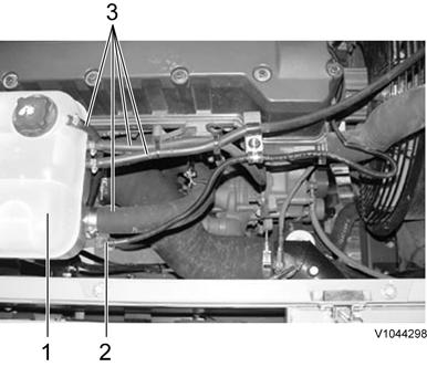
Figure6
Removal, expansion tank
12.Remove foot step (1).
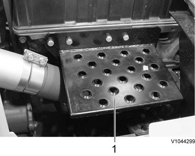
Figure7 Removal, step
13.Disconnect radiator hose (2) and upper charge air cooler hose (1).
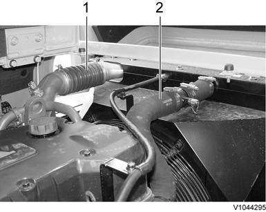
Figure8
Removal, radiator and charge air cooler hose
14.Disconnect hose (1) of engine oil remote filter bypass.
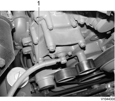
Figure9
Disconnect, hose
15.Remove radiator fan guard (1).
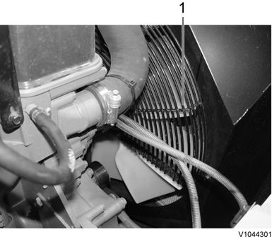
Figure10
Removal, radiator fan guard
16.Remove radiator fan (1).
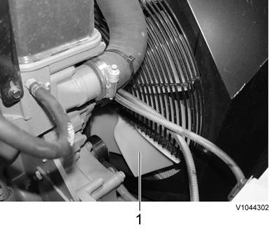
Figure11
Removal, radiator fan
17.Disconnect turbocharger inlet hose (1).
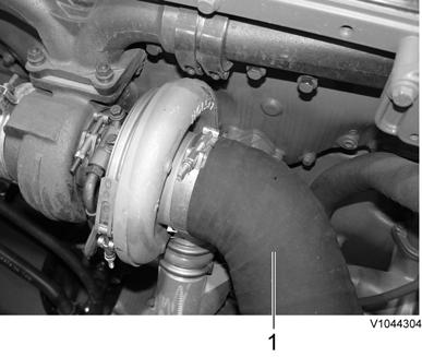
Figure12
Disconnect, hose
18.Disconnect cab heater hoses on the engine block and coolant pump.
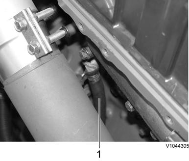
Figure13
Disconnect, hose
1.Cab heater hose on engine block
19.Open the machine right side cover.
20.Remove the main pump. See 913 Hydraulic pump, replacing
21.Disconnect the fuel line hoses (4 pcs).
NOTE!
Ports must be plugged after disassembling hoses.
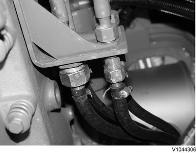
Figure14
Disconnect, hose
22.Remove the pump gearbox coupling. See 442 Pump gearbox coupling assembly, replacing
23.Disconnect starter motor wire harness (1).
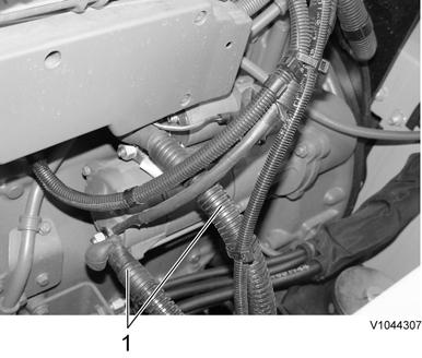
Removal, wire harness
24.Disconnect inlet hose (2), outlet hose (1) on the engine PTO pump.
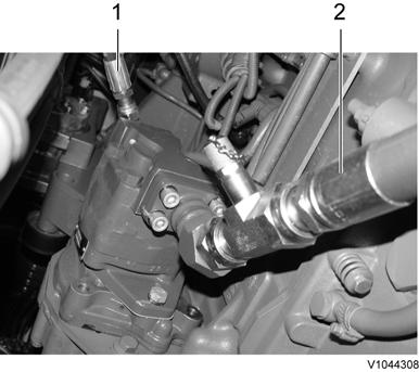
Removal, inlet and outlet hose
Do not disconnect or loosen connections for the air conditioning unit (AC). Risk of gas leakage.
25.Remove the compressor from the engine.
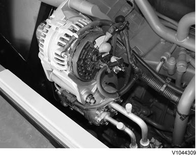
Figure17
Removal, compressor
26.Disconnect the wire harness for all engine sensors.
27.Remove cover (1) and disconnect main wire harness (2).
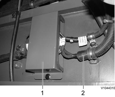
Figure18
Removal, cover
28.Disconnect radiator lower hose (1) and charge air cooler lower hose (2).
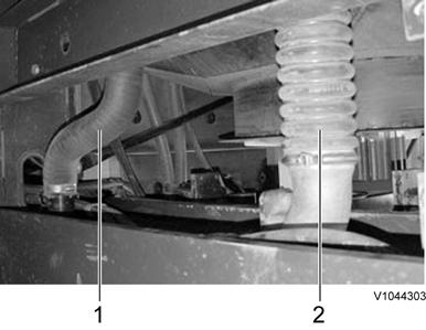
Figure19
Disconnect, radiator and charge air cooler hose
1. 2. Radiator hose
Charge air cooler hose
29.Disconnect the engine oil remote hose (1).
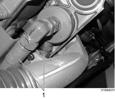
Figure20
Disconnect, hose
30.Remove the engine mounting screws (4 places).

Figure21
Removal, mounting screws
WARNING
The parts are heavy. Take appropriate safety precautions.
31.Fit tool 9998257 and connect 9998547 and a lifting device to the engine and remove the engine slowly.
Document Title: Function Group: Information Type:Date: Engine, installing 210 Service Information 2014/12/23
Profile: EXC, EC360C L [GB]
Engine, installing
Op nbr210-072
9998257 Lifting tool 9998547 Lifting device
NOTE!
Cable ties and clamps that secure hoses and electrical wring must be removed and then replaced wheninstalling.
WARNING
The parts are heavy. Take appropriate safety precautions.
1.Fit tool 9998257 and connect lifting device 9998547 and hoist the engine slowly and install the engine.
2.Install the engine mounting screws (4 places).
NOTE!
Pay attention to the positioning of the brackets, cushions, and mounting screws (front/rear) when assembling.
Figure1 Installation, engine
3.Connect engine oil remote hose (1).
Connect, hose
4.Connect radiator lower hose (1) and charge air cooler lower hose (2).
Figure3
Connect, hose
1. 2. Radiator hose Charge air cooler hose
5.Install cover (1) and connect main wire harness (2).
Figure4
Installation, wire harness and cover
6.Connect wire harness for all sensors to the engine.
7.Install the compressor to the engine.
Installation, compressor
8.Connect inlet hose (2) and outlet hose (1) of the engine PTO pump.
Connect, hose
9.Connect wire harness (1) to the starter motor.
Connect, wire harness
10.Connect the fuel line hoses (4 pcs).
Figure8
Connect, fuel hose
11.Install the pump gearbox coupling. See 442 Pump gearbox coupling assembly, replacing
12.Install the main pump. See 913 Hydraulic pump, replacing
13.Connect the cab heater hoses to the engine block and water pump rear side.
Figure9
Connect, hose
1.Cab heater hose on engine block
14.Connect turbocharger inlet hose (1).
Figure10
Connect, hose
15.Install radiator fan (1).
Figure11
Installation, radiator fan
16.Install radiator fan guard (1).
Figure12
Installation, radiator fan guard
17.Connect hoses (1) for remote engine oil bypass filter.
Figure13
Connect, hose
18.Connect radiator hose (2) and charge air cooler hose (1) on upper side.
Figure14
Connect, hose
19.Install foot step (1).
Figure15
Installation, foot step
20.Connect wire harness connector (2), hoses (3), and install expansion tank (1) with the bracket.
Figure16
Connect, wire harness and hose
21.Install the cowl using a lifting device.
22.Install the cowl mounting screws.
23.Install the engine rear cover.

If the above button click is invalid.
Please download this document first, and then click the above link to download the complete manual.
Thank you so much for reading
Figure17
Installation, cover
24.Install screws (1) and open radiator hood (2).
Figure18
Installation, radiator hood
25.Install silencer hood (1).
Figure19
Installation, silencer hood
26.Fill the hydraulic oil. See 173 Hydraulic system, changing oil
27.Fill the coolant through the expansion tank. See 261 Coolant, changing
28.Turn on the battery disconnect switch.
29.Start the engine and check for leaks and repair if needed.