
Document Title:
Product plates Function Group: 000 Information Type: Service Information Date: 2014/11/4
Profile:
EXC, EC210C L, EC160C L, EC180C L [GB]
Product plates
When ordering spare parts, and in all telephone enquiries or correspondence the model designation and the Product Identification Number (PIN) must always be quoted.
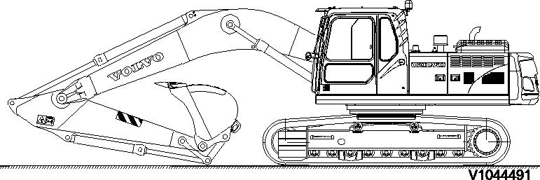
Product plate
The product plate on the machine shows the manufacturer's name and address, model designation, PIN, machine weight, engine output, production year and year of delivery. There is also room for the CE mark. The plate is positioned under the boom on the superstructure frame.
Engine
The engine product plate contains type designation and part and serial numbers and is positioned on the engine inside the rear engine cover on the right side of the machine.
Attachment quick coupler
The attachment quick coupler nameplate is attached on the outside of the attachment quick coupler. (shows part number and weight)
Bucket
The bucket nameplate is attached on the top of the bucket. (shows the bucket model order No, Serial number, bucket part number, rated capacity, weight, cutting width, tooth part number and adapted part number)
Cab
The nameplate is attached on the inside of the cab and indicates the product number, serial number, model type, and weight.

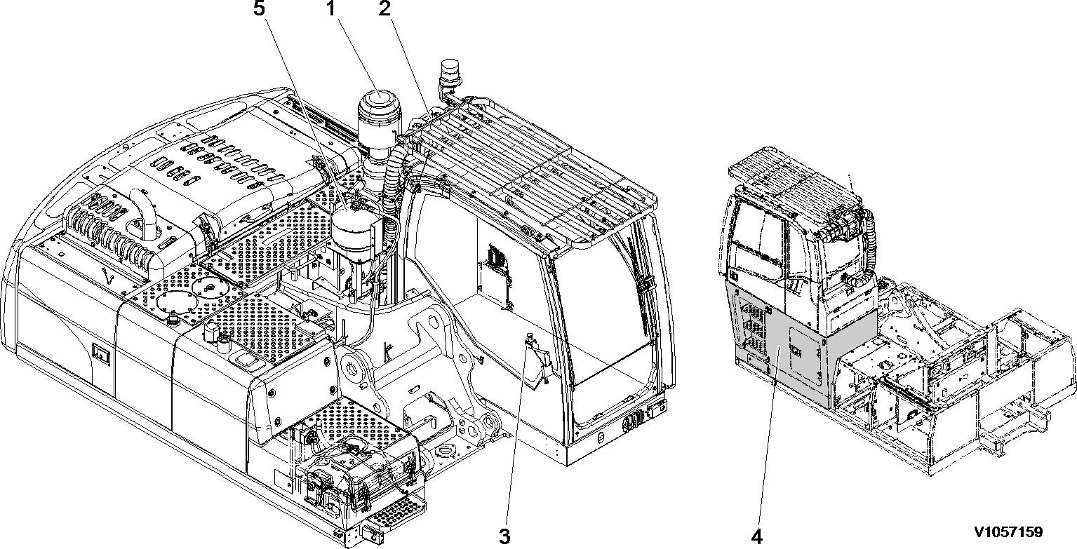
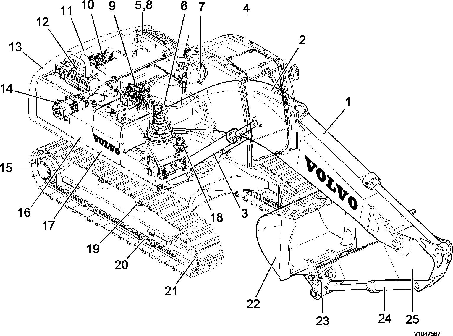
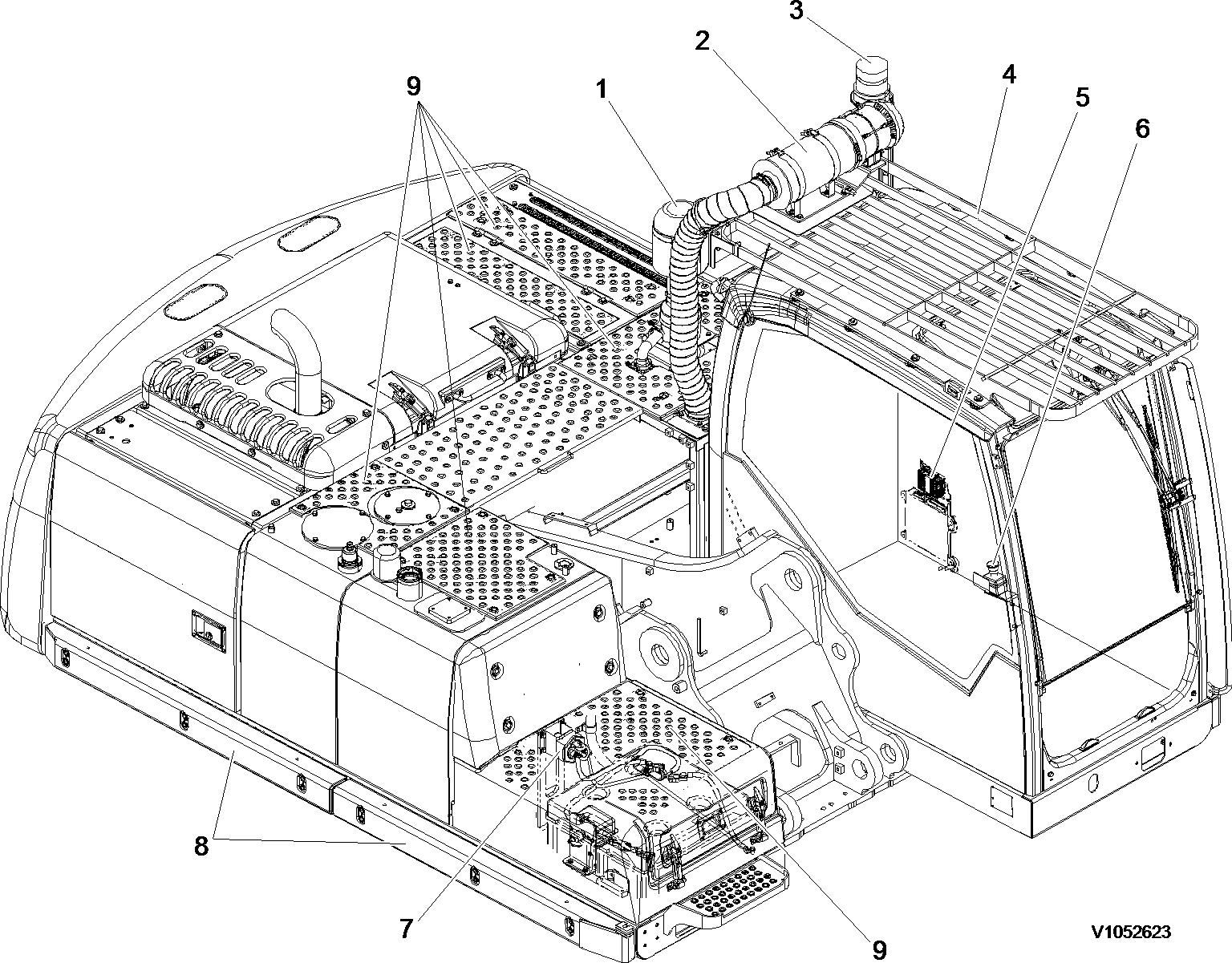
Document Title: Machine view, waste handler
Profile: EXC, EC210C L [GB]
Function Group: 000 Information Type: Service Information Date: 2014/11/4
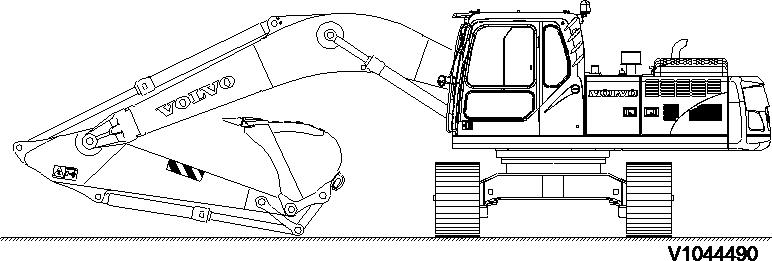
Machine view, waste handler
Waste handling machines have a variety of configurations to meet waste handling application needs.
Specially, the machines are reinforced Dual stage pre-cleaner, Cab air filtering system, Emergency stop switch, Cab riser, Fire extinguisher system and Bucket cylinder guard to fulfill an excellent performance in waste handling application.
Document Title: Machine view, waste handler Function Group: 000
Profile: EXC, EC210C L [GB]
Machine view, waste handler
Document Title: Measurement conversion tables
EXC, EC210C L [GB]
Measurement conversion tables
Weight
1 tonne(metric) = 1.1023 ton(US) = 0.9842 ton(UK)
Pressure
Approximate conversions
Torque
(lbf·ft)
Pressure (Pa = N/m2 )
kilopascal (kPa) x 4.0 = in. H2O x 0.249 = kPa
kilopascal (kPa) x 0.30 = in. Hg x 3.38 = kPa
kilopascal (kPa) x 0.145 = psi x 6.89 = kPa (bar) x 14.5 = psi x 0.069 = (bar)
(kgf/cm2) x 14.22 = psi x 0.070 = (kgf/cm2 ) (newton/mm2 ) x 145.04 = psi x 0.069 = (bar)
megapascal (MPa) x 145 = psi x 0.00689 = MPa
Power (W = J/s)
kilowatt (kW) x 1.36 = PS (cv) x 0.736 = kW kilowatt (kW) x 1.34 = HP x 0.746 = kW
kilowatt (kW) x 0.948 = Btu/s x 1.055 = kW watt (W) x 0.74 = ft·lb/s x 1.36 = W
Energy (J = N·m)
kilojoule (kJ) x 0.948 = Btu x 1.055 = kJ joule (J) x 0.239 = calorie x 4.19 = J
Velocity and Acceleration
meter per sec2 (m/s2 ) x 3.28 = ft/s2 x 0.305 = m/s2 meter per sec (m/s) x 3.28 = ft/s x 0.305 = m/s kilometer per hour (km/h) x 0.62 = mph x 1.61 = km/h
Horse power/torque
BHP x 5252 rpm = TQ (lb·ft)
Temperature
°C = (°F - 32) /1.8 °F = (°C x 1.8) + 32
Flow Rate
TQ x rpm 5252 = B.H.P.
liter/min (dm3/min) x 0.264 = US gal/min x 3.785 = liter/min
Note: ( ) non-si unit
Document Title: Standard tightening torques
Function Group: 030
Information Type: Service Information Date: 2014/11/4
Profile:
EXC, EC210C L [GB]
Standard tightening torques
The following charts give the standard tightening torques of screws and nuts. Exceptions are given in each sections of “disassembly and assembly”.
Tightening torque (meter)
Screw
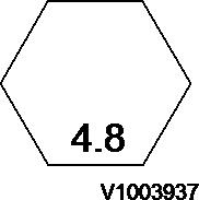
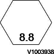
M
Tightening torque (inch)
NOTE!
This torque table does not apply to screws with nylon packings or where nonferrous metal washers are to be used, or which require tightening to a different specified torque, or tightening procedure.
NOTE!
N m (Newton meter):1 N m ≅ 0.1 kgf m
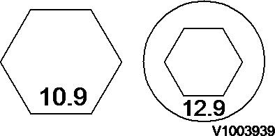
Tightening torque of split flange screws
Use these torques for split flange screws.
Tightening torque (split flange screws)
Thread
Tightening torque for hydraulic plugs with O-ring
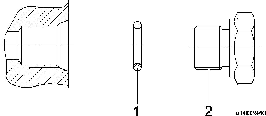
Hydraulic plugs with O-ring
1. O-ring
2. Plug
Pf thread
Tightening torque (hydraulic plugs)
1/4 9415–11022
Tightening torque for swivel nut fitting with O-ring
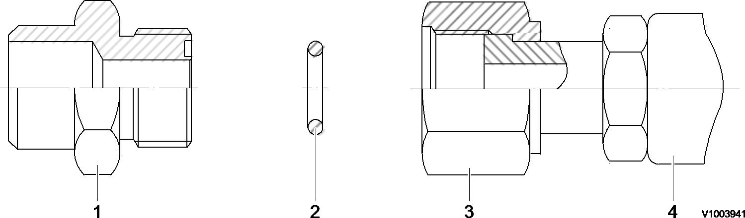
Tightening torque for swivel nut fitting
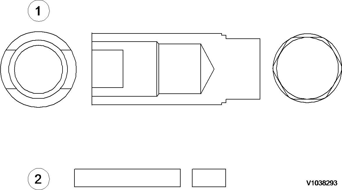
Document Title: NET 8940-00200 Replace tool for the remote control valve joint
Function Group: 080
Information Type: Service Information Date: 2014/11/4
Profile: EXC, EC210C L [GB] NET 8940-00200 Replace tool for the remote control valve joint
Document Title: E-tools, NET 8940-00270
Replace tool for the swing ring gear
Function Group: 080
Information Type: Service Information Date: 2014/11/4
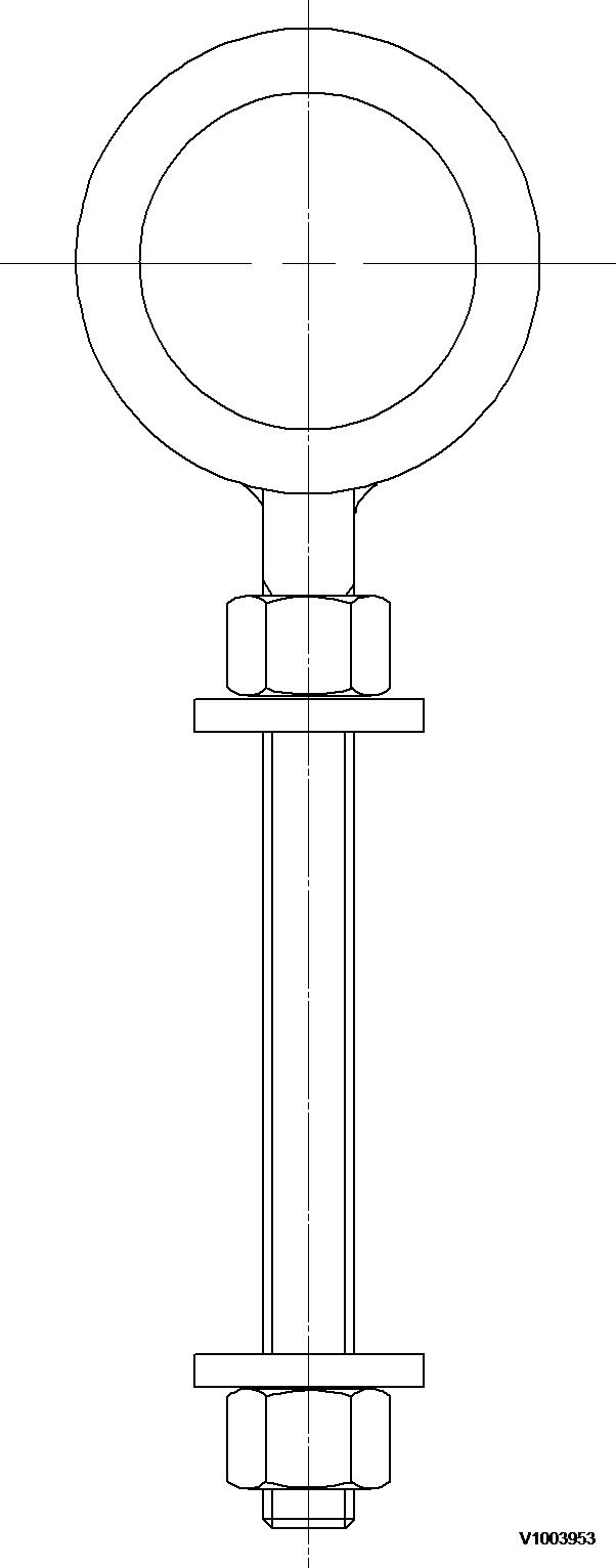
Figure 1 Replace tool for the swing ring gear
Document Title:
E-tools, NET 8940-00300
Swing ring gear guide pin
Profile: EXC, EC210C L [GB]
Function Group: 080
Information Type: Service Information Date: 2014/11/4
E-tools, NET 8940-00300 Swing ring gear guide pin
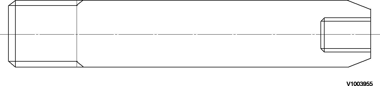
Figure 1
Slew ring gear guide pin Item
1
Document Title:
NET 8940-00290 Track motor guide pin
Function Group: 080
Information Type: Service Information
Date: 2014/11/4
Profile: EXC, EC210C L [GB]
NET 8940-00290 Track motor guide pin
Figure 1
Track motor guide pin
Item Quantity Name
Remark
1 2 Guide bar SAE 4130 (25 ~ 35 HRC)
2 2 Screw M8 × 16
Document Title:
Service positions
Profile: EXC, EC210C L [GB]
Service
positions
Function Group: 091
Information Type: Service Information
Park the machine on a horizontal and firm surface. The suitable position is indicated in the description for the various service jobs.
1
Service position A
2
Service position B
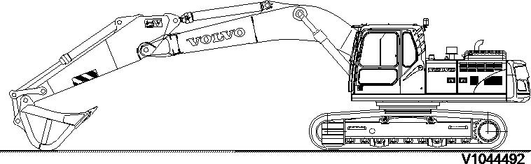
Figure 3
Service position C
4
Service position D
Date: 2014/11/4
Document Title:
Welding on the machine
Profile:
Function Group: 091
EXC, EC210C L, EC160C L, EC180C L [GB]
Welding on the machine NOTICE
Information Type: Service Information Date: 2014/11/4
During electric welding on the machine or attachments connected to the machine, components such as bearings and electric units may be damaged if the ground cable is connected incorrectly.
The following actions should be taken before starting electric welding to eliminate these risks:
1. Turn off the electric power using the battery disconnector.
2. Disconnect the batteries.
NOTE!
Both the plus and minus terminal.
3. Disconnect the following electronic units:
– Vehicle electronic control unit (V-ECU)
– Engine electronic control unit (E-ECU)
– Instrument electronic control unit (I-ECU)
– Electronic climate control unit (ECC)
– Wiper control unit (CU3601)
4. Connect the welding unit's ground connection as close as possible to the welding point, and make sure that the current does not pass across a bearing.
If welding is necessary on the boom or dipper arm, the following basic rules should be followed:
1. Welding beads should be laid down in the longitudinal direction.
2. If possible, weld in the middle of the metal section and never closer than 80 mm to an edge.
3. Do not weld near the welded connections of the cylinder mounting eyes. Minimum distance from eye's weld to weld for weld lug = 100 mm
4. Do not weld close to where a metal plate has been bent.
Document Title: Hydraulic cylinders, dieseling
Function Group: 091
Information Type: Service Information Date: 2014/11/4
Profile:
EXC, EC210C L, EC160C L, EC180C L [GB]
Hydraulic cylinders, dieseling
If air enters the hydraulic cylinders during work on the hydraulic system, this can lead to spontaneous ignition, an effect known as dieseling. This occurs if a favourable mixture of air and hydraulic oil is compressed when the piston approaches its end position in the cylinder. A sufficiently high temperature can be reached for the mixture to spontaneously ignite.
NOTICE
The dieseling effect may result in burnt piston seals and bushings.
In order to prevent dieseling, the lines for the hydraulic cylinders must be bled after work is completed, as follows:
Operate the digging equipment several times with no load and full cylinder strokes.
Position the dipper arm and bucket cylinders so that any air collects at the cylinder's outlet side, that is, it should be the highest point. The piston should be at the opposite end of the cylinder. Wait approx. 1 minute from the time that the cylinder has reached its position before running the piston towards the outlet side. Repeat 3 to 5 times.
The boom cylinders, which cannot be pointed downward, must be run in and out approx. 5 times without bucket load.
NOTICE
If the cylinders are pressurized either through lifting of the machine or lifting of a load in the bucket, without first performing the mentioned bleeding movements, the seals will likely be damaged.
If a cylinder is to be pressure-tested after a repair, the piston rod should be run in and out a few times before increasing the pressure to testing pressure.
Document Title: Control units, changing
Profile:
Function Group: 091
EXC, EC210C L, EC160C L, EC180C L [GB]
Control units, changing
Information Type: Service Information Date: 2014/11/4
Before changing electronic control unit Volvo CE product specialist should be consulted.
NOTE!
Before changing a control unit, customer parameters must be read out so that they can be programmed again.
Thank you for your purchase. Have a nice day.
15:13:48]