Disassembling reduction gear
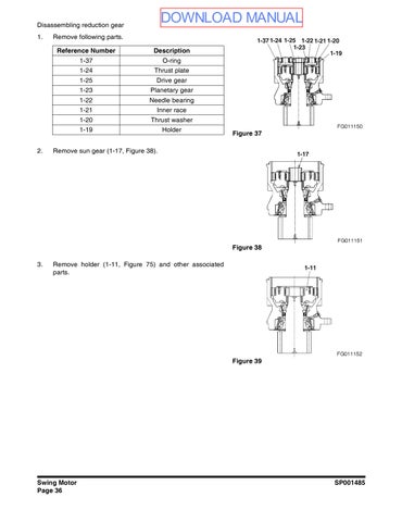
1.Remove following parts.
Disassembling reduction gear
1.Remove following parts.
Reference NumberDescription
1-37O-ring
1-24Thrust plate
1-25Drive gear
1-23Planetary gear
1-22Needle bearing 1-21Inner race
1-20Thrust washer
1-19Holder
2.Remove sun gear (1-17, Figure 38).

37

3.Remove holder (1-11, Figure 75) and other associated parts.

4.Secure holder (1-11, Figure 75) in a vice and loosen screw (1-16, Figure 40) to remove thrust plate (1-15, Figure 40).
NOTE: The screw is hard to remove because Loctite was used during assembly. To facilitate removal of screw, warm screw with a drier.
5.Remove following parts.
Reference NumberDescription
1-14Planetary gear
1-13Needle bearing 1-12Inner race
6.Remove following parts.
Reference NumberDescription 1-10Collar 1-9Plate
NOTE: When replacing taper roller bearings (1-6, Figure 45) and (1-8, Figure 42), collar (1-3) and plate (1-4), they are to be replaced by body assembly.
7.Remove pinion shaft (1-2, Figure 43).
When removing shaft, be careful not to drop it. If it is hard to remove, lightly strike it with a plastic hammer.

40

41

Figure 42

Figure 43
8.Remove inner race of taper roller bearing (1-8, Figure 42).

9.Break oil seal (1-7, Figure 44) to remove it.
The removed oil seal must not be used again. When removing it, exercise with care to prevent damage to outer races of taper roller bearings (1-8, Figure 42) and (1-6, Figure 45).

10.Remove outer race of taper roller bearing (1-8, Figure 42) and plug (1-35, Figure 46).

Precautions for assembly
1.Wash all parts with treated oil and blow oil completely.
2.Be sure that washed parts are free of dust and other foreign material. Handle them with care so they will not be dented or damaged.
3.Always replace seals, bearings and pins with new ones.
4.Tighten all tightening areas to specified torque.
5.Apply grease to oil seals and O-rings in advance. (In particular, oil seal lips must be oiled.)
6.Many small parts are used. Exercise care so as not to lose them (such as dropping them in holes).
Assembly
Assemble parts by following procedure.
Assembling motor
1.Install relief valve assembly (2- 38, Figure 47).
Tightening torque: 157±10Nm.
2.Assemble check valve (2-39, Figure 48) and spring (2-40, Figure 48).

47

48
3.Install plug (2-41, Figure 49).
Tightening torque: 39.2±2.0Nm
4.* With timer valve type
Install the O-ring (2-29-2-4, Figure 50) on the sleeve (2-291, Figure 50).
5.* With timer valve type
Assemble the sleeve (2-29-1, Figure 50) in the case (2-1, Figure 51) and set the spool (2-29-5, Figure 51), the washer (2-34, Figure 51) and the spring (2-35, Figure 51) in the hole of the sleeve.
6.Install plug (2-37, Figure 51).
Tightening torque: 84±5Nm
7.Assemble collar (2-6, Figure 52), spring (2-7, Figure 52) and washer (2-8, Figure 52) in cylinder block (2-5, Figure 52).
Be sure to assemble collar (2-6, Figure 52) in correct direction.

49

50

Figure 51
Figure 52
8.While pushing washer (2-8, Figure 54), assemble retaining ring (2-9, Figure 54).

53
9.Apply grease to pin (2-10, Figure 55) and assemble it in cylinder block (2-5, Figure 52).
10.Assemble retainer holder (2-11, Figure 55).
54
11.Set piston assembly (2-13, Figure 56) on retainer plate (2-12, Figure 56) and assemble it in cylinder block (2-5, Figure 52).
Apply an ample amount of hydraulic fluid to sliding part before assembly.
55
I
56
12.Press fit ball bearing (2-2, Figure 57) on shaft (2-3, Figure 57).
Press Fit ball bearing (2-2, Figure 57) with attached retaining ring facing as shown in figure.

57
13.Press fit shaft (2-3, Figure 58) and ball bearing (2-2, Figure 57) in case (2-1).

58
14.Apply grease to back of thrust plate (2-14, Figure 61) and assemble it.
The thrust plate must be assembled in correct direction.

Figure 59

60
15.Assemble cylinder block (2-5, Figure 61) and other associated parts.
During assembly, be sure that pin (2-10, Figure 61) will not come out.
*2: The disk (2-14, Figure 61) is assembled only for parking brake spec. only.
16.* With parking brake type
Apply grease to O-ring (2-16, Figure 62) and O-ring (2-17, Figure 62) and assemble them on brake piston (2-15, Figure 62).
17.* With parking brake type
While paying attention to location of hole of pin (2-25, Figure 68), assemble brake piston (2-15, Figure 63) in case (2-1, Figure 51).
18.* With parking brake type
Assemble spring seat (2-19, Figure 63) and disk spring assembly (2-18, Figure 63) in correct direction. Pay attention to orientation

61
62

63
64
19.Apply grease to O-ring (2-20, Figure 65) and assemble it in case (2-1, Figure 51).
Check to see if pin (2-25, Figure 65) can be assembled in brake piston and case hole. If not, remove brake piston (2-15, Figure 63) and reorient it, then reassemble. (*2 Parking brake spec. only)
Assemble pin (2-25, Figure 65) while being attached on cover.
20.Apply grease to O-ring (2-26, Figure 66) and pin (2-25, Figure 66), then assemble them in cover (2-21, Figure 66).
Press fit ball bearing (2-22, Figure 66).

65
66
21.Install pin (2-23, Figure 67), then install valve plate (2-24, Figure 67).
To prevent falling, apply grease to back side.
22.While paying attention to location of pin (2-25, Figure 68), install cover (2-21, Figure 68) and other associated parts to case (2-1, Figure 51).
Exercise care so pin (2-25, Figure 68) and valve plate (2-24, Figure 68) will not fall.
67

68