Operation and Maintenance Manual


天然气发电机发动机
Generator Natural Gas Engine
GV158TI
GV158TI
GV180TI
GV222TI
GV180TI
GV222TI
FOREWORD
This manual is designed to serve as a reference for DOOSAN Heavy Industries & Machinery Ltd's (here after DOOSAN’s) customers and distributors who wish to gain basic product knowledge on DOOSAN's GV158TI, GV180TI, GV222TI natural gas generator engines.
These economical and high-performance natural gas engines(GV158TI 8 cylinders) (GV180TI 10 cylinders), (GV222TI 12 cylinders) are 4 strokes and V-type have been so designed and manufactured to be used for the generator & power unit application. They meet all the requirements such as low noise, fuel economy, high engine speed and durability.
To maintain the engine in optimum condition and retain maximum performance for a long time, CORRECT OPERATION and PROPER MAINTENANCE are essential.
In this manual, the following symbols are used to indicate the type of service operations to be performed.


Removal
Installation
Disassembly
Reassembly
Align the marks
Directional Indication
Inspection
Measurement
Adjustment
Cleaning
Pay close attention-Important
Tighten to specified torque
Use special tools of manufacturer's
Lubricate with oil
Lubricate with grease
During engine maintenance, please observe following instructions to prevent environmental damage;
⚫ Take old oil to an old oil disposal point only.
⚫ Ensure without fail that oil and diesel fuel will not get into the sea or rivers and canals or the ground.
⚫ Treat undiluted anti-corrosion agents, antifreeze agents, filter element and cartridges as special waste.
⚫ The regulations of the relevant local authorities are to be observed for the disposal of spent coolants and special waste.
If you have any question or recommendation in connection with this manual, please do not hesitate to contact our head office, dealers or authorized service shops.
For the last, the content of this maintenance instruction may be changed without notice for some quality improvement and please feel free to contact to our agents near by your location for any services. Thank you.
Doosan Infracore Co., Ltd. Sept. 2004

1. Safety Regulations
1.1. General notes
Day-to-day use of power engines and the service products necessary for running them presents no problems if the persons occupied with their operation, maintenance and care are given suitable training and think as they work.
This summary is a compilation of the most important regulations, These are broken down into main sections which contain the information necessary for preventing injury to persons, damage to property and pollution. In addition to these regulations those dictated by the type of engine and its site are to be observed also.


IMPORTANT:
If despite all precautions, an accident occurs, in particular through contact with caustic acids, fuel penetrating the skin, scalding from oil, antifreeze being splashed in the eyes etc, consult a doctor immediately.
1.2. Handle compressed natural gas safety
Natural gas is highly flammable and explosive and may be extremely cold. The following cautions must be taken to avoid personal injury or engine damage
⚫ Do not smoke when installing or servicing the engine or fuel system.
⚫ Installation or servicing of natural gas equipment must only be conducted in well ventilated, natural gas compatible areas. Do not install or service equipment in an enclosed area where ignition sources are present without ensuring that an undetected gas leak may be safely vented without being ignited.
⚫ Do not vent natural gas or permit leaks inside an enclosed area. Bleed natural gas lines before installing or servicing any component connected to the fuel lines.
1.2.1. Avoid heating near pressurized fluid lines
⚫ Wear welding goggles and gloves when welding or using an acetylene torch.
⚫ Insure a that metal shield separated the acetylene and oxygen which must be chained to a cart.
⚫ Do not weld or heat areas near fuel tanks or fuel lines.
1.2.2. Venting an operable engine to relieve natural gas pressure
⚫ To avoid personal injury an operable natural gas engine must be kept in a well ventilated area away from open flames and sparks.
⚫ If the engine can run, use the following venting procedure to relive the natural gas pressure downstream of the shutoff valve.
1) Shut off manual valves on natural gas supply tanks and main shutoff valve on natural gas fuel supply line.
2) Start engine and run until it stalls due to fuel starvation.
3) Check to make sure gauge pressure at point on the natural gas fuel line to be vented has been reduced to zero. If not, repeat step 1) Then repeat step 2).
4) Disconnect vehicle batteries using switch in battery compartment or by disconnecting battery ground cable.


5) Slightly loosen the NG fuel line fitting to be serviced in a well ventilated area to allow any remaining gas to vent.
6) Completely open the fitting that was slightly opened and allow to vent in a well ventilated area.
1.2.3. During commissioning, starting and operation
⚫ This is the safety alert symbol. When you see this symbol in this manual, be alert to the potential for personal injury.


⚫ Carefully read all safety message in this manual and on your safety signs. Be sure new equipment components and repair parts include the current safety signs.
⚫ Avoid possible injury or death from runaway. Do not start engine by shorting across starter terminals.
⚫ Prevent fires by keeping machine clean of accumulated trash, grease, fuel and debris.
⚫ When the engine is running, do not get too close to the rotating parts.
⚫ Do not touch the engine with bare hands when it is warm from operation risk of bums.
⚫ Exhaust gases are toxic. If it is necessary to run an engine in an enclosed area, remove the exhaust gases from the area with an exhaust pipe extension. If you do not have an exhaust pipe extension, open the doors and get outside air into the area.
⚫ Keep vicinity of engine free of oil and grease. Accidents caused by slipping can have serious consequences.
1.2.4. During maintenance and care
⚫ Always carry out maintenance work when the engine is switched off. If the engine has to be maintained while it is running, e.g. changing the elements of change-over filters, remember that there is a risk of scalding. Do not get too close to rotating parts.
⚫ Change the oil when the engine is warm from operation.
CAUTION:
There is a rise of burns and scalding. Do not touch oil drain plug or oil filters with bare hands.

⚫ Take into account the amount of oil in the sump. Use a vessel of sufficient size to ensure that the oil will not overflow.
⚫ Open the coolant circuit only when the engine has cooled down. If opening while the engine is still warm is unavoidable, comply with the instructions in the chapter "Maintenance and Care".
⚫ Neither tighten up nor open pipes and hoses (lube oil circuit, coolant circuit and any additional hydraulic oil circuit) during the operation. The fluids which flow out can cause injury.
⚫ Fuel is inflammable. Do not smoke or use naked lights in its vicinity. The tank must be filled only when the engine is switched off.
⚫ When using compressed air, e.g. for cleaning the radiator, wear goggles.

⚫ Keep service products (anti-freeze) only in containers which can not be confused with drinks containers.
⚫ Comply with the manufacturer's instructions when handling batteries.
CAUTION:
Accumulator acid is toxic and caustic. Battery gases are explosive.
1.2.5. When carrying out checking, setting and repair work
⚫ Checking, setting and repair work must be carried out by authorized personnel only.
⚫ Use only tools which are in satisfactory condition. Worn open-end wrench slip. which could lead to Injury.
⚫ When the engine is hanging on a crane, no-one must be allowed to stand or pass under it. Keep lifting gear in good condition.
⚫ When working on parts which contain asbestos, comply with the notes.
⚫ When checking spark plug do not put your hands under the electric.
⚫ When working on the electrical system disconnect the battery earth cable first. Connect it up again last in prevent short circuits.
1.2.6. To prevent damage to engine and premature wear
(1) If faults occur, find the cause immediately and have it eliminated in order to prevent more serious of damage.
(2) Use only genuine DHIM spare parts. DHIM will accept no responsibility for damage resulting from the installation of other parts which are supposedly "just as good".
(3) In addition to the above, note the following points.
⚫ Never let the engine run when dry, i.e. without lube oil or coolant.
⚫ Use only DHIM-approved service products (engine oil, anti-freeze and anticorrosion agent).
⚫ Have the engine maintained at the specified intervals.
⚫ Do not switch off the engine immediately when it is hot, but let it run without load for about 5 minutes so that temperature equalization can take place.
⚫ Never put cold coolant into an overheated engine. See "Maintenance and care".
⚫ Do not add so much engine oil that the oil level rises above the max. marking on the dipstick. Do not exceed the maximum permissible tilt of the engine. Serious damage to the engine may result if these instructions are not adhered to.
⚫ Always ensure that the testing and monitoring equipment (for battery charge, oil pressure, coolant temperature) function satisfactorily.
⚫ Do not let the raw water pump run dry, If there is a risk of frost, drain the pump when the engine is switched off.
1.2.7. To prevent pollution
(1) Engine oil, filter elements, fuel filters
⚫ Take old oil only to an oil collection point.
⚫ Take strict precautions to ensure that oil does not get into the drains or into the ground. The drinking water supply could be contaminated.
⚫ Filter elements are classed as dangerous waste and must be treated as such.
(2) Coolant
⚫ Treat undiluted anti-corrosion agent and / or antifreeze as dangerous waste.
⚫ When disposing of spent coolant comply with the regulations of the relevant local authorities.
1.2.8. Notes on safety in handling used engine oil
Prolonged or repeated contact between the skin and any kind of engine oil decreases the skin.
Drying, irritation or inflammation of the skin may therefore occur. Used engine oil also contains dangerous substances which have caused skin cancer in animal experiments. If the basic rules of hygiene and health and safety at work are observed, health risks are not to the expected as a result of handling used engine oil
Health precautions:
⚫ Avoid prolonged or repeated skin contact with used engine oil.
⚫ Protect your skin by means of suitable agents (creams etc.) or wear protective gloves.
⚫ Clean skin which has been in contact with engine oil.
- Wash thoroughly with soap and water, A nailbrush is an effective aid.
- Certain products make it easier to clean your hands.
- Do not use petrol, Diesel fuel, gas oil, thinners or solvents as washing agents.
⚫ After washing apply a fatty skin cream to the skin.
⚫ Change oil-soaked clothing and shoes.
⚫ Do not put oily rags into your pockets.
Ensure that used engine oil is disposed of properly.
- Engine oil can endanger the water supplyFor this reason do not let engine oil get into the ground, waterways, the drains or the sewers. Violations are punishable. Collect and dispose of used engine oil carefully. For information on collection points please contact the seller, the supplier or the local authorities.
1.2.9. General repair instructions
1. Before performing service operation, disconnect the grounding cable from the battery for reducing the chance of cable damage and burning due to shortcircuiting.
2. Use covers for preventing the components from damage or pollution.
3. Engine oil and anti-freeze solution must be handled with reasonable care as they cause paint damage.
4. The use of proper tools and special tools where specified is important to efficient and reliable service operation.
5. Use genuine DOOSAN parts necessarily.
6. Used cotter pins, gaskets, O-rings, oil seals, lock washer and self-lock nuts should be discarded and new ones should be prepared for installation as normal function of the parts can not be maintained if these parts are reused.
7. To facilitate proper and smooth reassemble operation, keep disassembled parts neatly in groups. Keeping fixing bolts and nut separate is very important as they vary in hardness and design depending on position of installation.
8. Clean the parts before inspection or reassembly. Also clean oil ports, etc. using compressed air to make certain they are free from restrictions.
9. Lubricate rotating and sliding faces of parts with oil or grease before installation.
10. When necessary, use a sealer on gaskets to prevent leakage.
11. Carefully observe all specifications for bolts and nuts torques.
12. When service operation is completed, make a final check to be sure service has been done property.
1.3. Engine Specifications
1.3.1. Specification
Engine
Ignition
1.3.2. Engine Power
* Note : All data are based on operation without cooling fan at ISO 3046.


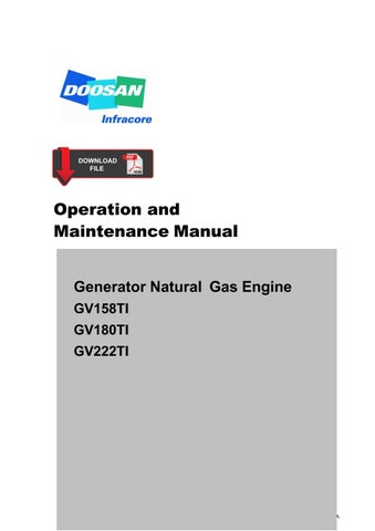
1.4.3. Engine Assembly Views

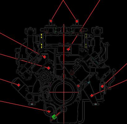
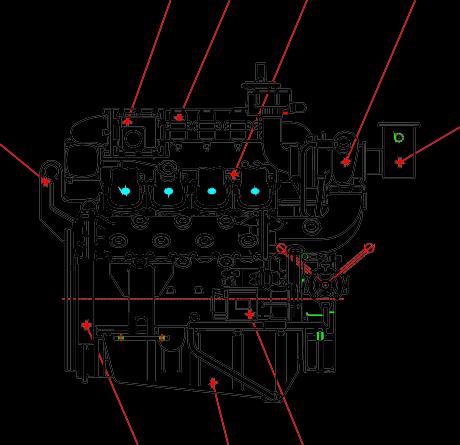


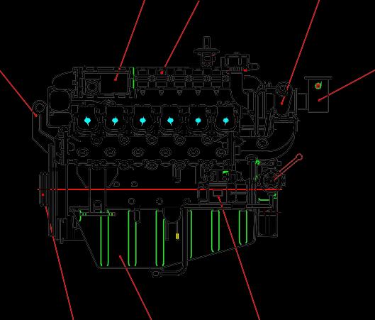
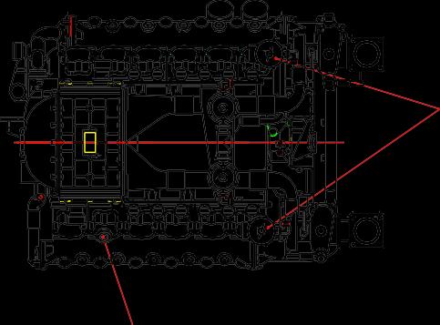
2. Technical Information
2.1. Engine model and serial number
⚫ The engine model and serial number is located on the engine as illustrated.

⚫ These numbers are required when requesting warranty and ordering parts. They are also referred to as engine model and serial number because of their location.

⚫ Engine serial No. (example 1 : GV158TI)
EEZOD 6 00001
Serial No. ProductionYear (2006) Engine Model
⚫ Engine serial No. (example 2 : GV180TI)
EESOA 6 00001

Serial No. ProductionYear (2004) Engine Model
⚫ Engine serial No. (example 3 : GV222TI)


EEYOC 6 00001
Serial No. ProductionYear (2006) Engine Model
2.2. Diagnostic display module(CPU-95)

⚫ The diagnostic display module is designed to operate in conjunction with a variety of display/control options.
⚫ This facilitates the application of diagnostic display module systems to gas engines operating at varying stages of automation and sophistication.
CAUTION:
1. Do not connect or disconnect the diagnostic display module to/from the wiring harness without first removing the negative (-) battery cable from the battery.
2. Do not perform remove the inner parts of the Diagnostic display module.
2.3. Engine characteristic
The DAEWOO GV158TI, GV180TI, GV22TIC natural gas engine is an overhead valve, turbo charged, water-to-air charge cooled, electronically controlled engine
2.3.1. Design characteristic

⚫ Spark-ignited by the spark plug
⚫ Electric engine control through the ECM(engine control module) system
⚫ Turbocharger with a water cooled bearing-housing
2.3.2. Natural gas
⚫ Natural gas is a clean burning fuel, and offers a low particulate emission. Natural gas is also a very economical fuel.
⚫ From the gas producing areas in the country, the distribution companies and local utilities from a complex nation-wide-delivery-network that supplies natural gas for home and industry use. The network is highly developed and extended to all major population center in the country.
2.3.3. Engine ignition system

⚫ This system changes the general combustion concept of the diesel engine. Specifically, it changes a compression-ignition diesel to a spark-ignited engine. However, this engine is unlike the typical generator engine that has spark plugs.
⚫ The primary difference is this system uses a combustion concept. That is, excess air is mixed In with the combustion system. When combined with a gaseous fuel like natural gas, it allows greatly reduced emissions compared to diesel, plus high efficiencies and excellent high-performance.
⚫ The GV158TI, GV180TI, GV222TI engine is an integrated package featuring computer-controlled electronic engine system by the engine speed controller. This system controls fuel, ignition and speed, and has engine protection features.
2.3.4. Engine speed controller : ESC
⚫ The Engine Speed Control is designed to provide basic isochronous speed control for gas engines using the Flo-Tech Throttle.
⚫ Engines with mechanical loads and generator loads are handled equally well.

2.3.5. Ignition control module : ICM

⚫ This digital ignition system has been designed for application on nature gas fueled engines.
⚫ This system is offers a variety of advanced control, emissions reduction, primary and spark diagnostics, self diagnostic serial communications and engine protection features.
2.3.6. Cylinder block
⚫ The cylinder block is a single piece of alloy cast iron. To increase its stiffness, it is extended to a level below the crankshaft center line. The engine has replaceable wet cylinder liners and individual cylinder heads.
2.3.7. Piston, con-rod and crankshaft
⚫ The forged crankshaft has screwed-on the balance weights. Radial seals with replaceable wearing rings on crankshaft and flywheel are provided to seal the crankcase penetrations.
⚫ The connecting rods are die-forged, diagonally split and can be removed through the top of the cylinders together with the pistons. Crankshaft and connecting rods run in steel-backed lead bronze ready-to fit type bearings.
2.3.8. Engine timing
⚫ Camshaft, oil pump and hall-effect sensor are driven by a gear train arranged at the flywheel end.
Hall-effectsensor gear (Z=51)

Drivegearofhall-effect sensor (Z=51)
Crankshaft gear (Z=43)
Oil pump drive gear (Z=44)
Camshaft gear (Z=86)
Oil pump gear (Z=7)
Oil pump gear (Z=7)
2.3.9. Valves
⚫ The overhead valves are actuated via chilled cast iron tappets, push rods and rocker arms from the camshaft.
2.3.10. Engine lubrication system
⚫ The engine is equipped with force-feed lubrication. The pressure is produced by a gear pump whose drive gear is in direct mesh with the crankshaft gear at the flywheel end.
⚫ The oil pump draws the oil from the oil sump and delivers it through the oil filter and oil cooler to the main distributor gallery and from there to the main bearings, big-end bearings and camshaft bearings as well as to the small-end bearings and the rocker arms.
⚫ The turbocharger is also connected to the engine lubricating system. The cylinder walls and timing gears are splash-lubricated.
⚫ Each cylinder has an oil jet provided for cooling the underside of the pistons. The lube oil is cleaned in a full-flow oil filter.
⚫ Depending on the agreed extent of delivery and the design of the engine, the lube oil circuit can be equipped with oil pressure monitors (advance warning and cutoff function) which shut the engine down in the event of a sudden loss of pressure.
2.3.11. Oil cooler

⚫ An oil cooler is provided between the oil filter and the crankcase. This cooler is of the flat tube type with turbulence inserts and operated by the coolant.
2.3.12. Engine oil
⚫ Check oil level with the oil level gauge and replenish if necessary.
⚫ Check the oil level with the engine cooled. If the engine is warm, allow time for 5 10 minutes for oil drain into the crankcase before checking oil level. The oil level must be between Max. and Min. lines on the gauge.
⚫ Engine oil should be changed at the specified intervals. Oil in the oil filter cartridge should be changed simultaneously
⚫ The following oils are also recommended
SAE No. API No. Sulfated ash content
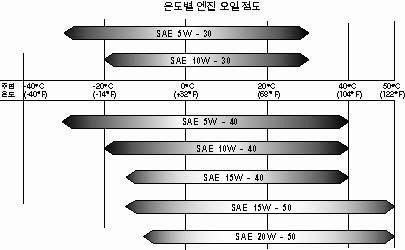
15W40 above CD or CE Bellow 0.5 %
Recommend oil : TOTAL LMG-405
Mobil Delvac super GEO 15W40
⚫ Engine oil capacity

Ambient temperature
2.3.13. Exchanging of lubrication oil
⚫ Engine oil and the oil filter are important factors affecting engine life. They affect ease of starting, fuel economy, combustion chamber deposits and engine wear.
⚫ While the oil is still hot, discharge the sump oil by motion oil drain pump lever manually as figure.
⚫ Refill new engine oil to the filler neck on the head cover in accordance with the oil capacity of the engine. Be careful about the mixing of dust or contaminator during the supplement of oil. Then confirm whether the oil level gauge indicates the vicinity of its maximum level.
⚫ For a few minutes, operate the engine at idling in order to circulate oil through lubrication system. Thereafter shut down the engine. After waiting for about 10 minutes measure the quantity of oil and refill the additional oil if necessary.


2.3.14. Replacement of oil filter cartridge
⚫ Every time oil exchanges, replace the oil filter cartridge.
⚫ Drain engine oil by loosening the drain plug on the filter head.
CAUTION:
Don't forget tightening the drain plug after having drained engine oil.
⚫ Remove the oil filter by turning it counter-clockwise with a filter wrench.
⚫ Wipe, clean the fitting face of the filter body and the oil filter body with a rag so that the new oil filter cartridge can be seated properly.
⚫ Lightly oil the O-ring and turn the oil filter until O-ring is fitted against the seal face. And then turn it in addition by 3/4 ~1 turns further with hand or the filter wrench.
NOTE:
It is strongly advisable to use DAEWOO genuine oil filter cartridge for replacement.
2.3.15. Cooling System
⚫ The engine has a liquid-cooling system. The water pump is a maintenance-free impeller pump driven by V-belts from the crankshaft pulley.
⚫ Depending on the agreed extent of delivery and the design of the engine, the coolant circuit can be equipped with temperature monitors which, in the event of loss of coolant, shut the engine down.
2.3.16. Cooling water
⚫ Regarding the cooling water that is to be used for engine, the soft water not the hard water must be used.
⚫ The engine cooling water can be used diluting it with antifreezing solution 40% and the additive for rust prevention (DCA4) 3 ∼ 5 %.
⚫ The density of above solution and additive must be inspected every 500 hours to maintain it properly.
NOTE :
The proper density control of antifreezing solution and rust preventing additive will be able to prevent the rusting effectively and maintain the stable quality of engine.
For the improper control might give the fatal damage to the cooling water pump and cylinder liners, detail care is needed.
⚫ Since GV158TI, GV180TI, GV222TI(Engine of D28 base engine) cylinder liner is wet type, particularly the cooling water control should be applied thoroughly.
⚫ The density of antifreezing solution and additive for rust prevention is able to be confirmed by the cooling water test kit.
(Fleetguard no. : CC2602M or DAEWOO no. : 60.99901-0038)
⚫ How to use the cooling water test kit
(1) When the cooling water temp. of engine is in the range of 10 ∼ 55 C, loosen the plug for cooling water discharge and fill the plastic cup about a half.
NOTE:
In taking the cooling water sample, if the water in auxiliary tank were taken, it is hard to measure the accurate density. Take the cooling water sample necessarily loosening the cooling water discharge plug.
(2) At the state of a test paper soaked in the sampled water, after taking the paper out through water agitation, shake off the water.
(3) Wait for about 45 sec. till the color change of test paper.
NOTE: However, it should not elapse longer than 75 sec, and if it did, the hue would change.
(4) Make the numerical value by comparing the test paper which hue has changed with the color list of label on storage bottle.
(5) By comparing the hue changed into yellowish green or so with the green color indication of test paper storage bottle, confirm the density. (Then, the density indication must be in the hue range of 33% to 50%).
(6) The brown at the middle of test paper and the lower pink color indication represent the additive state for rust prevention, and the proper range is that the meeting numerical value of brown (vertical) and pink color (horizontal) locates in the range of 0.3 to 0.8 at the color list of label on the test paper storage bottle.
(7) In case of less than 0.3, replenish the additive for rust prevention (DCA4), and in case of more than 0.8, pour out the cooling water about 50% and then readjust the density after refilling with clean fresh water.
⚫ Amount of Anti-freeze in winter
⚫ Use a V - belt of specified dimensions, and replace if damaged, frayed, or deteriorated.
⚫ Check the V - belt for belt tension. If belt tension is lower than the specified limit, adjust the tension by relocating the alternator.
(specified deflection: 10 15 mm when pressed down with thumb)

2.3.18. Air Cleaner


⚫ Air cleaner is mounted on the engine to purify the air for combustion. The intervals at which the air cleaner requires servicing depend on the specific operating conditions encountered. Clogged air filters may cause black smoke and reduce power.
⚫ A check should be made from time to time to see that the fastening elements securing the air cleaner to the intake manifold seal the connection tightly. Any ingress of unfiltered air is liable to cause a high rate of cylinder and piston wear.
2.3.19. Intercooler
⚫ The intercooler is water to air type. The intercooler life and performance depends on the intake air condition greatly. Fouled air pollutes and clogs the air fins of intercooler. As a result of this, the engine output is decreased and engine malfunction is occurred.
⚫ So you always check whether the intake air systems like air filter element are worn or polluted.
2.3.20. Valve ClearanceAdjust Procedure
⚫ After letting the #1 cylinder's piston come at the compression top dead center by turning the crankshaft, adjust the valve clearances.
⚫ Loosen the lock nuts of rocker arm adjusting screws and push the feeler gauge of specified value between a rocker arm and a valve stem and adjust the clearance with adjusting screw respectively and then tighten with the lock nut.
⚫ As for the valve clearance, adjust it when in cold, as follows.
0.30 mm 0.40 mm
⚫ Adjusting Sequence of Valve Clearance (1 Type)
- By cranking the engine, let #1 cylinder's valves overlap.
- In time, adjust the valve clearance corresponding to “ ” of lower lists.
- In time, turning crankshaft one full turn, let the valves of #7 (10 cylinder engine) or #6 (8 cylinder engine and 12 cylinder engine) cylinder's valves overlap.


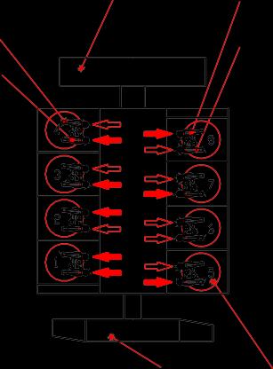
- Adjust the valve clearance corresponding to “ ” of lower lists.
- After reinsuring the valve clearances, retighten if necessary.