VALVE
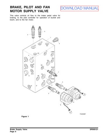
This valve controls oil flow to the brake pedal valve for braking, to the pilot controller for operation of bucket and boom, and to the fan motor.
DOWNLOAD MANUAL
Brake Supply Valve
1
Figure
Reference Number Description
1Body (200*120*79)
2Sequence (C1)
3 Reducing (C2)
4Check (C3)
Brake Supply Valve
Reference Number Description
5Solenoid (C4 and C5)
6Coil (C4 and C5)
7Relief Valve (C6)
SP000121
Specifications
ItemSpecifications
Max. Operating Pressure
210.0 kg/cm2 (3,000 psi)
Max. Flow57 l/min (15 U.S. gpm)
System Pressure
Setting PressureC1
C2
C3 Cracking Pressure
C6
120.0 kg/cm2 (1,710 psi)
120±2 kg/cm2 at 53 l /min (1710±28 psi at 14 U.S. gpm)
30 kg/cm2 at 20 l /min (427 psi at 5.3 U.S. gpm)
2.40 kg/cm2 (34.1 psi)
190.0 kg/cm2 (2,700 psi)
Port SizeFO, F1, MPF 1/2 O-ring
TP1, TP2, T2PF 1/4 O-ring
LP, PKø30 PF 1/4 BSP
All other portsPF 3/8 O-ring
Brake Supply Valve
FG004516
Figure 2 Hydraulic Circuit
Parking Brake
SP000122 Parking Brake
SAFETY PRECAUTIONS
CAUTION!
Follow all safety recommendations and safe shop practices outlined in the front of this manual or those contained within this section.
Always use tools and equipment that are in good working order.
Use lifting and hoisting equipment capable of safely handling load.
Remember, that ultimately safety is your own personal responsibility.
APPLICABLE MODELS
The contents of this section apply to the following models and serial number ranges.
MODELSERIAL NUMBER RANGE
DL4005001 and Up
DL5005001 and Up