SERVICE MANUAL
English
2017
Part number 48127449
May
CX37C Mini Excavator
English
2017

CX37C Cab - T ier final engine
CX37C Canopy - T ier final engine
Excavator and backhoe bucket hydraulic system
Swing arm hydraulic system Dozer blade cylinders
T rack frame and driving wheels
T racks
T rack tension units
connectors
Cab engine controls
Engine control system
Engine starting system Alternator
Battery
Fuel tank system
Engine intake and exhaust system
Engine cooling system
Engine oil system 1
Cab controls
Cab controls (Lift Dipper , Bucket)
Wiper and washer system
External lighting
External lighting switches and relays
Cab lighting
Hydraulic contamination
General specification
Fluids and lubricants
Product identification
Product identification - Machine orientation
All repair and maintenance work listed this manual must carried out only qualified dealership strictly complying with the instructions and whenever the special
Anyone who performs repair and maintenance operations without complying with the procedures provided herein shall responsible for any subsequent
The manufacturer and all the organizations its distribution chain, including - without limitationnational, regional, local reject any responsibility for damages caused parts and / components not approved the facturer , including those used for the servicing repair the product manufactured marketed the manufacturer any case, warranty given attributed the product manufactured marketed the manufacturer case damages caused parts and / components not approved the manufacturer
The manufacturer reserves the right make improvements design and changes specifications any time without notice and without incurring any obligation install them units previously and illustrative material herein are accurate known time publication but are subject change without notice.
case refer your CASE
Personal safety
This the safety alert used alert you potential personal injury Obey all safety messages that follow this symbol avoid possible death injury

Throughout this manual you will find the signal words W and CAUTION followed special These precautions are intended for the personal safety you and those working with
Read and understand all the safety messages this manual before you operate service the
DANGER indicates a hazardous situation not will result death serious injury
W
ARNING indicates a hazardous situation not could result death serious injury
CAUTION indicates a hazardous situation not could result minor moderate injury
F AILURE T O FOLLOW DANGER, W ARNING, AND CAUTION MESSAGES COULD RESUL T DEA SERIOUS INJUR Y .
Machine safety
NOTICE: Notice indicates a situation that, not avoided, could result machine property damage.
Throughout this manual you will find the signal word Notice followed special instructions prevent machine property damage. The word Notice used address practices not related personal safety .
Information
NOTE: Note indicates additional information that clarifies other information this
Throughout this manual you will find the word Note followed additional information about a step, other information the The word Note not intended address personal safety property
Cleaning
Clean the metal parts with cleaning solution that meets the standard and steam (except for bearings)
After cleaning, dry well, and inject oil all parts.
Also inject oil into the bearings after
Inspection
When disassembling check all the there are any worn damaged replace Inspect carefully prevent initial
Bearing
Replace any loose
Air dry bearings before installing
Needle bearing
When inserting needle very careful not damage
Apply grease the section where the needle bearing will
Gear
Check that there wear and Oil seal, Oring, gasket
Always install new oil O - and
Apply grease sections where oil seals and O - rings will
Shaft
Check that there wear and
Check the bearings and check for damaged oil seals the shaft.
Service parts
Install CASE CONSTRUCTION genuine service parts.
When placing order , check the parts contains the CASE CONSTRUCTION genuine part
Any breakdowns arising from the installation non - genuine parts are not covered the warranty
Lubricants (fuel, hydraulic oil)
Use the oil from the specified company specified the manual service
Any breakdowns arising from any fuel hydraulic oil other than those specified are not covered the warranty
Preliminary warnings maintenance operation
W ARNING
A void injury!
Shut off the engine, remove the key , and make sure all machine motion stops before you service the machine.
Failure comply could result death serious injury
Improper operation service this machine can result accident.
128B
Assign a supervisor direct worksite Agree all safety and suitable hand signals.

Failure comply could result death serious injury .
Pinch hazard!
Always use suitable tools align mating parts. NOT use your hand fingers.
Failure comply could result minor moderate injury
Personal Protective Equipment (PPE)
W ARNING
A void injury!
W0287A
C0044A
Use Personal Protective Equipment (PPE), including protective goggles, gloves, and safety footwear .
Failure comply could result death serious injury .
Lifting operation
W ARNING
Crushing hazard!
W1036A
The lifting systems must operated qualified personnel who are aware the correct procedures follow . Make sure all lifting equipment good condition, and all hooks are equipped with safety latches.
Failure comply could result death serious injury
Heavy objects!
W0256A
Lift and handle all heavy components using lifting equipment with adequate capacity Always support units parts with suitable slings hooks. Make sure the work area clear all bystanders.
Failure comply could result death serious injury
Improper operation service this machine can result accident.
W0398A
Raised equipment machine movement without operator can cause serious injury . Always the following before performing any maintenance: Park the machine flat, level ground.
Lower the attachment the
Shut down the engine and remove the ignition key . Lock the tracks.
Failure comply could result death serious injury W0944D
T - over hazard!
Only raise the track little necessary .
Failure comply could result death serious injury
Hydraulic system
W ARNING
Burn hazard!
W0276A
Before performing any service the hydraulic system, you must allow cool. Hydraulic fluid temperature should not exceed (104 °F).
Failure comply could result death serious injury W0241A
Pressurized fluid can penetrate the skin and cause severe injuries. The grease the cylinder under high Never loosen the grease fitting adaptor completely order speed the flow grease.
Failure comply could result death serious injury . W0261A
W ARNING
Pressurized system!
Before attempting any service procedure, your responsibility know the number accumulators the and the correct procedure for releasing the pressure each accumulator
Failure comply could result death serious injury . W0136A
Battery W ARNING
Battery acid causes burns. Batteries contain sulfuric acid.
A void contact with skin, eyes clothing. Antidote (external): Flush with water . Antidote (eyes): flush with water for minutes and seek medical attention immediately . Antidote (internal): Drink large quantities water milk. not induce vomiting. Seek medical attention immediately .
Failure comply could result death serious injury
Battery gas can explode!
T o prevent explosion: Always disconnect the negative ( battery cable Always connect the negative ( battery cable last. not short circuit the battery posts with metal objects. not weld, grind, smoke near a battery .
Failure comply could result death serious injury W001
Fluids W ARNING
Hazardous chemicals!
Coolant can toxic. A void contact with skin, eyes, and clothing. Antidotes:
EXTERNAL - Rinse thoroughly with water . Remove soiled clothing.
INTERNAL - Rinse the mouth with water NOT induce Seek immediate medical
EYES - Flush with water . Seek immediate medical attention.
Failure comply could result death serious injury W0282A
Burn hazard!
Hot coolant can spray and scald you remove the radiator deaeration tank cap while the system T o remove the cap: allow the system turn the cap the first and wait for all pressure release. Remove the cap only after all pressure has released.
Failure comply could result death serious injury
Escaping fluid!
W0367A
Hydraulic fluid diesel fuel leaking under pressure can penetrate the skin and cause infection other injury T o prevent personal injury: Relieve all pressure before disconnecting fluid lines performing work the hydraulic system. Before applying pressure, make sure all connections are tight and all components are good Never use your hand check for suspected leaks under pressure. Use a piece cardboard wood for this purpose. injured leaking fluid, see your doctor immediately .
Failure comply could result death serious injury
Chemical hazard!
W0178A
When handling and other service follow the W ear Personal Protective Equipment (PPE) instructed. not smoke use open flame. Collect fluids proper containers. Obey all local and environmental regulations when disposing
Failure comply could result death serious injury .
W0371A
Soil, air , and water quality important for all industries and life general. When legislation does not yet rule the treatment some the substances that advanced technology sound judgment should govern the use and disposal products a chemical and petrochemical
Familiarize yourself with the relative legislation applicable your country , and make sure that you understand this Where legislation obtain information from suppliers anticleaning agents, etc., with regard the fect these substances man and nature and how safely store, use, and dispose these
• A void the use cans other inappropriate pressurized fuel delivery systems fill Such delivery systems may cause considerable
• avoid skin contact with all Most these products contain substances that may harmful your
• Modern oils contain not burn contaminated fuels and waste oils ordinary heating
• A void spillage when you drain fluids such used engine coolant engine hydraulic brake etc. not mix drained brake fluids fuels with lubricants. Store all drained fluids safely until you can dispose the fluids a proper way that complies with all local legislation and available
• not allow coolant mixtures get into the soil. Collect and dispose coolant mixtures properly .
• The air - conditioning system contains gases that should not released into the Consult airtioning specialist use a special extractor recharge the system properly
• Repair any leaks defects the engine cooling system hydraulic system immediately
• not increase the pressure a pressurized circuit this may lead a component
• Protect hoses during Penetrating weld splatter may burn a hole weaken allowing the loss
Batteries and electric accumulators contain several substances that can have a harmful fect the environment the batteries are not properly recycled after Improper disposal batteries can contaminate the groundwater , and CASE CONSTRUCTION strongly recommends that you return all used batteries a CASE CONSTRUCTION dealer , who will dispose the used batteries recycle the used batteries properly . some countries, this a legal requirement.
NOTE: The following requirements are mandatory
Batteries are made lead plates and a sulfuric acid solution. Because batteries contain heavy metals such lead, CONAMA Resolution 401 / 2008 requires you return all used batteries the battery dealer when you replace any not dispose batteries your household
Points sale are obliged to:
• Accept the return your used batteries
• Store the returned batteries a suitable location
• Send the returned batteries the battery manufacturer for recycling
For each adjustment select adjusting shims and measure the adjusting shims individually using a eter , then add the recorded not rely measuring the entire shimming which may the rated value shown each
For correct rotating shaft seal proceed follows:
Before assembly , allow the seal soak the oil will sealing for least thirty Thoroughly clean the shaft and check that the working surface the shaft not Position the sealing lip facing the
NOTE: W ith hydrodynamic take into consideration the shaft rotation direction and position the grooves that they will move the fluid towards the inner side the
Coat the sealing lip with a thin layer lubricant (use oil rather than Fill the gap between the sealing lip and the dust lip double lip seals with grease.
Insert the seal its seat and press down using a flat punch seal installation not tap the seal with a hammer
While you insert the check that the seal perpendicular the When the seal make sure that the seal makes contact with the thrust
T o prevent damage the seal lip the position a protective guard during installation
Lubricate the O - ring seals before you insert them the This will prevent the O - ring seals from overturning and which would jeopardize sealing ficiency
Apply a sealing compound the mating surfaces when specified the
Before you apply the sealing compound, prepare the surfaces directed the product container .
Only use CNH Original Parts CASE CONSTRUCTION Original Parts.
Only genuine spare parts guarantee the same quality , and safety original they are the same parts that are assembled during standard production. Only CNH Original Parts CASE CONSTRUCTION Original Parts can fer this
When ordering spare parts, always provide the following information:
• Machine model (commercial name) and Product Identification Number (PIN)
• Part number the ordered which can found the parts catalog
T o avoid damage the electronic and / electrical systems, always observe the following practices: Never make break any the charging circuit connections when the engine including the battery
Never short any the charging components
Always disconnect the ground cable from the battery before arc welding the machine any machine
• Position the welder ground clamp close the welding area
• you weld close proximity a computer then you should remove the module from the
• Never allow welding cables lie near , across any electrical wiring electronic component while you weld.
Always disconnect the negative cable from the battery when charging the battery the machine with a battery charger
NOTICE: you must weld the unit, you must disconnect the battery ground cable from the machine battery . The electronic monitoring system and charging system will damaged this not
Remove the battery ground Reconnect the cable when you complete
Battery acid causes burns. Batteries contain sulfuric acid.
A void contact with eyes Antidote (external): Flush with water Antidote (eyes): flush with water for minutes and seek medical attention immediately . Antidote (internal): Drink large quantities water not induce Seek medical attention immediately
Failure comply could result death serious injury .
The special tools that CASE CONSTRUCTION suggests and illustrate this manual have been specifically searched and designed for use with CASE CONSTRUCTION The special tools are essential for reliable repair The special tools are accurately built and rigorously tested fer ficient and long - lasting
using these repair personnel will benefit from:
• Operating optimal technical conditions
• Obtaining the best results
• Saving time and fort
• W orking safe conditions
T
NOTE: discoloration cylinder rod can occur when the friction reduction additive lubrication oil spreads the rod surface. Discoloration does not cause any harmful effect the cylinder
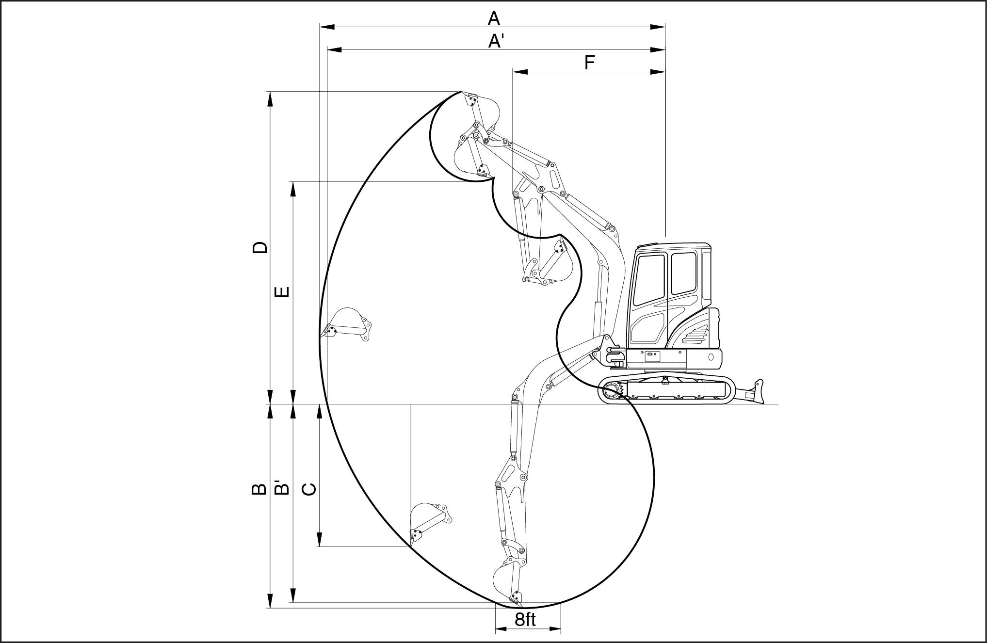
shoes – Steel double grouser
Cab version
length: 2.5 m ( 98.425 )
length: m ( )
Contamination the hydraulic system a major cause the malfunction hydraulic Contamination any foreign material the hydraulic
Contamination can enter the hydraulic system several ways:
• When you drain the oil disconnect any line
• When you disassemble a component
• From normal wear the hydraulic components
• From damaged seals worn seals
• From a damaged component the hydraulic system
All hydraulic systems operate with some contamination. The design the components this hydraulic system mits ficient operation with a small amount increase this amount contamination can cause problems the hydraulic
The following list includes some these problems:
• Cylinder rod seals that leak
• Control valve spools that not return neutral
• Movement control valve spools dif ficult
• Hydraulic oil that becomes too hot
• Pump and other parts that wear rapidly
• Relief valves check valves held open dirt
• Quick failure components that have been repaired
• Slow cycle times are slow The machine does not have enough power
your machine has any these check the hydraulic oil for
There are two types contamination: microscopic and
Microscopic contamination occurs when very fine particles foreign material are suspended the hydraulic These particles are too small see Microscopic contamination can found identification the following problems testing a laboratory
Examples problems caused microscopic contamination:
• Cylinder rod seals that leak
• Control valve spools that not return neutral
• The hydraulic system has a high operating temperature
V isible contamination foreign material that can found odor V isible contamination can cause a sudden failure
Examples problems caused visible contamination:
• Particles metal dirt the oil
• Air the oil
• Dark thick oil
• Oil with odor burned oil
• W ater the oil
you find contamination, use a portable filter clean the hydraulic system.
48127449 09/05/2017
Introduction Fatty Acid Methyl Ester AME) biodiesel
F AME biodiesel, called biodiesel fuel the following section, consists a family fuels derived from vegetable oils treated with methyl
There are two main biodiesel fuel types: Rapeseed Methyl Ester (RME) and Soybean Methyl Ester RME a blend rapeseed and sunflower methyl ester , and the preferred crop SME the preferred crop the United
Biodiesel fuel a renewable alternative fuel Its use and development promoted especially Europe and the United
NOTICE: Y our emissions control system compatible with 5 % biodiesel fuel ( aware that the use biodiesel fuel that does not comply with the standards mentioned this section could lead severe damage the fuel system after treatment system your The use non - approved fuels may void CASE CONSTRUCTION W arranty
Biodiesel fuel can used run diesel engines pure biodiesel fuel when blended with standard diesel fuel:
• : indicates the blend 5 % biodiesel and % diesel
NOTICE: Never use biodiesel blends higher than .
Biodiesel fuel has several positive features comparison with diesel fuel:
• Biodiesel fuel adds lubricity the fuel, which beneficial many circumstances, particularly sulfur and matics are removed from the
• Biodiesel has a greater cetane number and burns cleaner
• Biodiesel produces less particulate matter and reduces smoke
• Biodiesel fully biodegradable and non -
TIER 4 FINAL diesel fuel specifications are covered the following:
• ASTM D975 , Standard Specification for Diesel Fuel (15 ppm sulfur
Biodiesel blends are covered by:
• United States Diesel Fuel Specification ASTM D975 allows 5 % biodiesel since United States fuel suppliers are allowed use 5 % biodiesel fuel (B5) supply the
• United States Biodiesel Fuel Specification ASTM D7467 provides specifications for biodiesel blends from
Pure biodiesel (B100) specification covered the following requirements:
• ASTM D6751 - Standard specification for biodiesel fuel blend stock (B100) for middle distillate
Before raw oil can converted into usable biodiesel must undergo transesterification remove During the transesterification the oil reacts with alcohol separate the glycerine from the fat vegetable oil. This process leaves behind two products: methyl ester (the chemical name for biodiesel) and glycerine uct usually sold for use soaps other
NOTICE: Biodiesel fuels approved for use the CASE CONSTRUCTION equipment must transesterified and comply with the North America Standard ASTM D6751
NOTICE: Cold Pressed Biodiesel, Cold Pressed Oil, Straight V egetable Oil (SVO), more generally unrefined etable oils used motor are fuels that are normally made from Rapeseed oil similar high oil content These kinds fuel are not they not fulfil the ASTM D6751 There nized quality standard available for these types Therefore the use Cold Pressed Cold Pressed
Straight V egetable Oil more generally unrefined vegetable oils used motor fuel are NOT APPROVED any blend any CASE CONSTRUCTION
NOTICE: Any engine and fuel injection equipment fitted a CASE CONSTRUCTION vehicle found have run with any blend NON - APPROVED fuel (fuel not fulfilling the specification described the requirement ASTM D6751 ) will longer covered for W arranty CASE CONSTRUCTION
Biodiesel fuel usage conditions
Y must stringently follow the biodiesel fuel usage
Incorrect application the biodiesel fuel usage ditions could lead severe damage the engine, fuel injection equipment and aftertreatment system.
The main concerns related operation with biodiesel fuels are:
• Filters and injector blockage caused poor fuel quality
• W ear and corrosion internal components due water which fects lubricity
• Deterioration some rubber sealing compounds the fuel system.
• Biodiesel which can lead the formation deposits that can harm the fuel injection
NOTICE: Any problem the engine fuel injection equipment associated with non - compliance the following tions for biodiesel fuel handling and maintenance will not covered for W arranty CASE CONSTRUCTION .
Purchase biodiesel fuel from a trusted supplier who understands the product and maintains acceptable fuel quality highly recommended that you use biodiesel from 9000 accredited suppliers maintain the quality and sistency the The 9000 Quality Management Program accredited the National Biodiesel Board for producers and marketers biodiesel See the National Biodiesel Board website www for more
The machine should not stored for long periods without changing the diesel fuel the fuel
NOTICE: Biodiesel highly hygroscopic and tends collect water more than diesel This increases the risk algae and bacteria growth which can cause severe damage the fuel injection Keep the machine fuel tanks and - site storage tanks full possible limit the amount air and water vapors inside the tank. Drain water from the tanks least once a
the machine should stored for long periods, make sure replace the diesel fuel every three months most.
using appropriate fluids and lubricants the excavator can operate ambient temperatures ranging from( - 4 ) ( 1 )
NOTICE: when operating the machine ambient temperatures outside the above mentioned consult your CASE CONSTRUCTION dealer for specific machine provision and for specific fluids and lubricants used.
CASE CONSTRUCTION requires the use a fully formulated Organic Acid T echnology (OA based coolant. CASE AKCELA ACTIFULL™ EXTENDED LIFE COOLANT the reference genuine
NOTICE: use different coolant brands not
NOTICE: never add Supplemental Coolant Additives (SCA) when using CASE AKCELA ACTIFULL™ EXTENDED LIFE COOLANT .
NOTICE: never mix CASE AKCELA ACTIFULL™ EXTENDED LIFE COOLANT coolant with conventional Mixing T based coolant with conventional coolant will reduce the effectiveness T
NOTICE: only conventional coolant a complete changeover the fluid into the cooling system shall carried out.
the engine cooling system shall always refilled with coolant solution made mixture antifreeze and distilled (deionized) water
NOTICE: never refill the cooling system with only antifreeze. Never refill the cooling system with only water .
Using CASE AKCELA ACTIFULL™ EXTENDED LIFE COOLANT , a / mixture antifreeze and distilled (deionized) water grants proper performance the engine cooling system the above mentioned operating ature range the
CASE AKCELA ACTIFULL™ EXTENDED LIFE COOLANT available as:
• / PREMIXED coolant solution ready for
• CONCENTRA antifreeze mixed / with distilled (deionized) water
NOTICE: operating extreme winter climate, a coolant solution made / antifreeze / distilled (deionized) water mixture shall used order grant proper performance the engine cooling
NOTICE: never use coolant solution with more than % This affects the cooling capacity the
When the coolant solution prepared starting from the CONCENTRA product, the antifreeze concentration the mixture antifreeze and distilled (deionized) water can determined with a refractometer designed measure ethylene glycol
distilled (deionized) water not use water for dilution with the following properties:
NOTICE: never use hard water , sea water and softened sea water that has been conditioned with salt. The minerals and salts present potable water can cause corrosion and deposits resulting shortened engine
For Europe only: use only Ultra - Low Sulphur Diesel (S10) that meets 590 specifications.
For North America only: use only 2 - D Ultra - Low Sulphur Diesel ( S15 ) that meets ASTM D975
Using other types fuel may lead stalled engine output deterioration fuel economy .
NOTICE: the warranty shall invalid any serious defect caused usage any other Using fuel other than recommended may cause damage the fuel injection injector , and other fuel supply system the CASE CONSTRUCTION may not responsible any such damages.
the temperature drops below the fuel cloud output deficiency engine start problems may occur due wax
For North America only: during cold weather , lower than - 7 ( 19.4 ) , temporarily acceptable use a mixture 1 - D (S15) and 2 - D (S15)
NOTICE: operating severe winter climate, consult the fuel supplier the CASE CONSTRUCTION dealer for specific diesel fuel
The diesel fuel used the machine shall:
• free from dust even minute
• have the proper viscosity
• have a high cetane number
• present great fluidity low
• have low sulphur
• have very little residual
NOTICE: never use a mix diesel fuel and old engine The fuel injection system and the exhaust after treatment system will severely
NOTICE: consult the fuel supplier the CASE CONSTRUCTION dealer regarding appropriate use fuel
NOTICE: order prevent condensation during cold weather , fill the fuel tank full after completing the
Fuel storage:
Long storage can lead the accumulation impurities and condensation the Engine trouble can often traced the presence water the fuel. The storage tank must placed outside and the temperature the fuel should kept low Drain f water and impurities regularly
Fluids, lubricants and spare parts used the machine are not fully compatible with the environment. Make sure carry out all maintenance operations using appropriate order avoid any risk damaging the
NOTE: for make sure that the receptacle for collecting oil replaced not
Never spread fluids lubricants the ground into water . Consult the CASE CONSTRUCTION dealer the Local Environmental Agency order obtain information the correct method disposing fluids and lubricants used the
Never throw away spare parts filters Consult the CASE CONSTRUCTION dealer the Local ronmental Agency order obtain information the correct method disposing batteries other spare parts used the
Y our machine a hydraulic excavator . consists undercarriage fitted with tracks and a swing bearing which supports the upper - structure The upper - structure frame supports the attachment the front end the plus the hydraulics and the cab / canopy When the operator works the the engine - driven pump delivers hydraulic fluid the control The control valves distribute the hydraulic fluid the various cylinders and hydraulic motors A cooling system maintains the hydraulic fluid normal operating
When ordering obtaining seeking always supply your CASE CONSTRUCTION Dealer with the type and Product Identification Number (PIN) your machine
W rite the following the spaces below:
• Machine T ype
• Machine PIN
• Machine year manufacture
• Serial numbers hydraulic and mechanical components
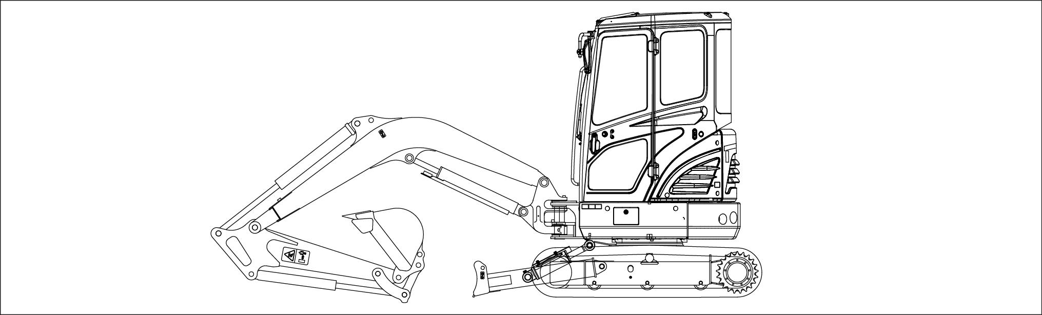
 SMIL16MEX0363EA 1 Cab version
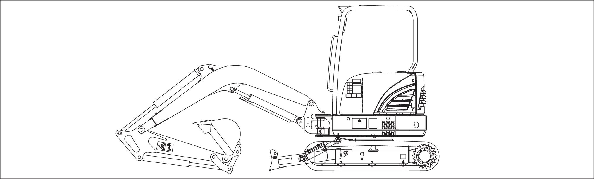
SMIL16MEX0629EA 2 Canopy version
SMIL16MEX0363EA 1 Cab version
SMIL16MEX0629EA 2 Canopy version
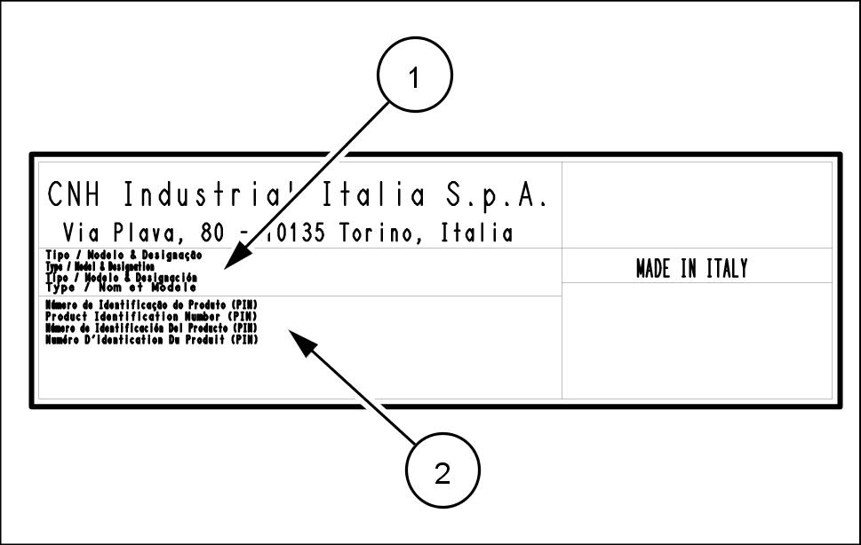
The machine Product Identification Number (PIN) plate (A) located below the front window the cab.
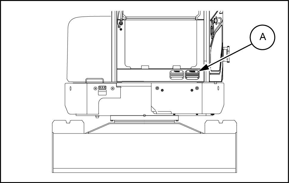
(1) T ype / Model
(2)
SMIL16MEX1460AB 3
Hydraulic Excavator___________________________
Product Identification Number (PIN)

SMIL16MEX1494AA 4
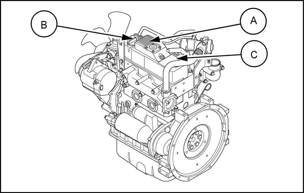
Engine
The engine serial number (A) located the engine name
SMIL16MEX1461AB 5
label (B)
This attached the cylinder head cover
SMIL16MEX1290AA 6
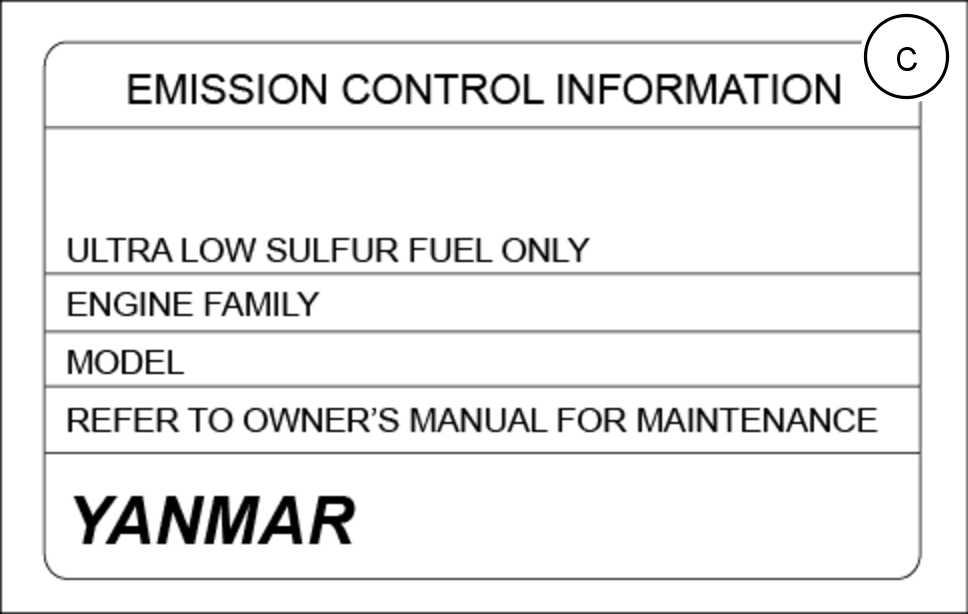
The emission decal fixed the cylinder head cover describes important details for using the Make sure read before using the the emission decal describes details regarding the engine only
SMIL16MEX1291AA 7
Structure protection Roll Over Protective Structure ( ROPS )
Complies with ISO 121 - 2 / ISO 10262 LEVEL 1
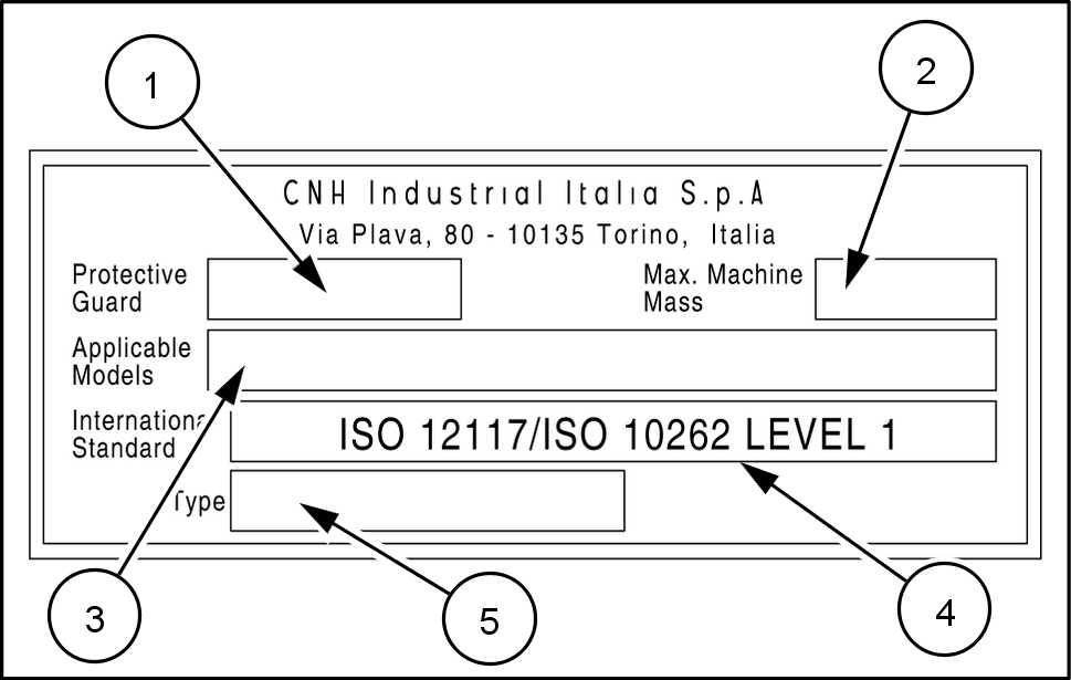
(1) T ype protective guard
(2) Maximum machine mass
(3) Applicable model
(4) International standard
(5) T ype
Component serial numbers
Hydraulic pump:
Swing reduction gear:
T ravel reduction gears:
T ravel control valve:
Attachment control valve:
Swing control valve:
SMIL16MEX0646AA 8
The terms - hand", - hand", and are used this manual indicate the sides they are seen from the seat when the travel motors are positioned the rear and the operator facing the tion which the machine advances
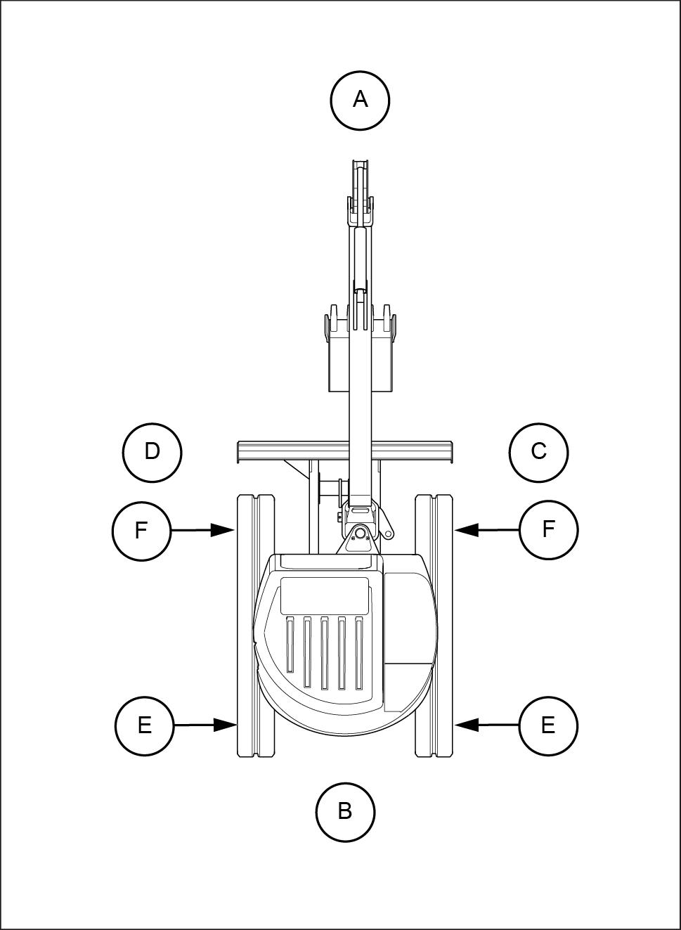
Front
Rear
Right - hand side
Left - hand side
T ravel motor
F Idler wheel
SMIL16MEX0357BB 1