
Document Title:
Counterweight,installation FunctionGroup: 73.6
Information Type: Service Information Date: 2015/5/4 0
Profile: DOWNLOAD SERVICE REPAIR MANUAL
Counterweight, installation
Opnbr7l6-02

Service Manual part

Allow the engine and exhaust pipe to cool before starting work in the engine compartment to prevent injuries.
The counterweight weighs 6 400 kg, keep the lifting tool tensioned so that the counterweight cannot fall when the screws are removed.
Make sure the counterweight is standing on a firm and level surface before removing the lifting tool. Prop up the counterweight carefully so that it cannot fall over.
1. Park the machine in service position A, [Invalid linktarget]
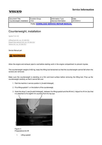
2. Fit a lifting eyebolt 1 on the bottom of the counterweigit.
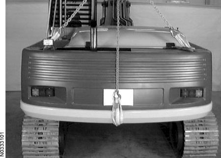
3. Hook the strop 3, see [Invalid linktarget] , between the lifting eyebolt and the lift link 2. Adjust the lift link 2so that it is attached to the eighth link counting from the top eye.
Lifting strop
Preparations for lift
Lift link
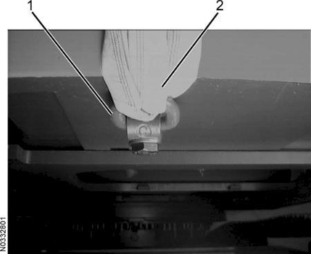
4. Fit strops in the counterweight's upper fastening points. Use protective pads t. so the strops are not damaged.
3
Upper fastening point
1. Protective pad
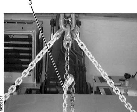
5. To prevent the strop from slipping and the Volvo emblem from getting damaged, use a block of wood or plastic as protection, as shown in [Invalid linktarget]
6. Tighten strops and lift links with the lifting device.
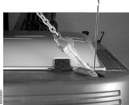
7. Lift up the counterweight and put it carefully in place on the frame beams. Be careful not to damage the edge for the cable 2.
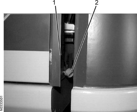
Figure S
Lifting the counterweight in place
1. Edge 2. Cable
8. Lower the counterweight and adjust its position with a crowbar.
9. Fit new screws on the bottom of the counterweight. Be careful with the screw threads. Tightening torque 3 200 Nm.
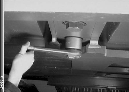
Bottom of counterweight
If a torque wrench is not available, tighten thescrews as described below.
10 Tighten the screws to about 100 Nm (pre-tightening).
11 Tighten the screws another 120° with the aid of the impact box wrench and the sleeve. {The angle 120° is equivalent to two edges on the screw head.)
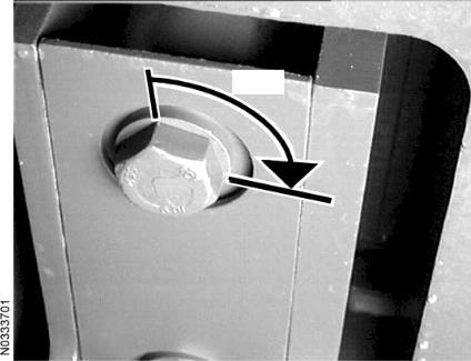
Angle tightening of screw
12 Remove lift links, strops and lifting eyebolts.
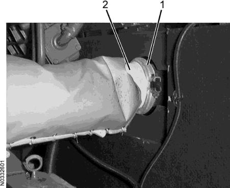
13. Fit the exhaust pipe 2 and the cIamp1.
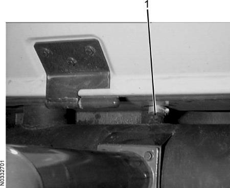
14 Fit the hose and the clamp 1.
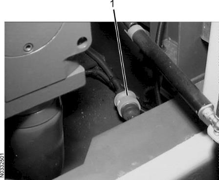
15. Put together the connector 1 for the power supply to the tail lights.
16. Close the door to the hydraulic pumps and the service door above the engine.