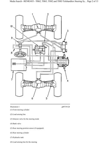

Illustration 1g00739128
(1) Front steering cylinder
(2) Load sensing line
(3) Selector valve for the steering mode
(4) Bank valve
(5) Rear steering position sensor (if equipped)
(6) Rear steering cylinder
(7) Hydraulic tank
(8) Load sensing line for the steering
(9) Steering metering pump
(10) Hydraulic pump
The hydraulic pump (10) is a variable displacement axial piston type. The pump output is matched to system requirements by a load sensing system in bank valve (4). The pump supplies oil to the steering section of the bank valve. When the steering system is not in operation, a small amount of oil from the steering section of the bank valve is metered to metering pump (9). The rest of the oil from the pump is directed to the implement control valves. The metering pump is connected to the load sensing system by line (8) .
When the steering system is not in operation, a small amount of supply oil flows through a dynamic signal orifice in the steering section of the bank valve. The orifice allows a constant flow of hydraulic oil to flow through the signal line to the metering pump and to the tank when the steering wheel is stationary. This improves steering response time in cold weather.
Steering mode selector valve (3) is a three-position solenoid operated valve which controls the rear axle steering cylinder.
Self-Aligning Rear Steering (If Equipped)
Rear steering position sensor (5) consists of a proximity switch that is mounted on the right side of the rear axle, and a target which is mounted on the right side steering yoke. The position sensor is de-energized when the upper half of the master steering select switch is depressed for operation in crab steer mode or circle steer mode.
Right Turn in Two-Wheel Steer Mode
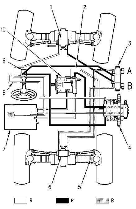
Illustration 2g00739134
(1) Front steering cylinder
(2) Load sensing line
(3) Selector valve for the steering mode
(4) Bank valve
(5) Rear steering position sensor (if equipped)
(6) Rear steering cylinder
(7) Hydraulic tank
(8) Load sensing line for the steering
(9) Steering metering pump
(10) Hydraulic pump
(R) Return oil
(P) Pump oil
(B) Blocked oil
When the top of the master steering select switch is depressed, the solenoids on mode selector valve (3) and position sensor (5) are de-energized. The valve spool is then centered by spring force, and the ports that connect rear steering cylinder (6) are blocked. Oil that is locked into the cylinder by the valve spool holds the rear wheels in the straight ahead position and the rear axle operates as a rigid axle.
When a right turn is made in two-wheel steer mode, oil flows through metering pump (9), through mode selector valve (3), and to the right side of front steering cylinder (1). Oil that enters the cylinder causes the tie rods to move to the left. This causes the wheels to move to the right. Oil in the left side of the steering cylinder flows to tank (7) through the metering pump.
Note: The wheels will turn faster when the steering wheel is turned faster.
If the steering cylinder reaches the end of the stroke and the operator continues to turn the steering wheel, pressure in the steering system will increase. The increase in pressure causes the signal relief valve in the end section of bank valve (4) to open and excess signal oil is directed to the tank in order to relieve the pressure.
When the steering wheel is turned to the left the flow of oil is reversed. Oil flows directly to the left side of the steering cylinder and return oil is routed through the mode selector valve and back to the tank.
Note: If the engine stops and the machine is in motion, the machine can still be steered. When the steering wheel is turned in this situation, the metering section of metering pump (9) acts as a pump.