This service manual is a guide to servicing of Cat Lift Trucks for 3.5 thru 7.0 ton models. The instructions are grouped by systems to serve the convenience of your ready reference.
Long productive life of your lift trucks depends to a great extent on correct servicing the servicing consistent with what you will learn from this service manual. We hope you read the respective sections of this manual carefully and know all the components you will work on before attempting to start a test, repair or rebuild job.
The descriptions, illustrations and specifications contained in this manual were of the trucks of serial numbers in effect at the time it was approved for printing. Cat Lift Trucks reserves the right to change specifications or design without notice and without incurring obligation.
The GM4.3 Liter engine’s fuel system was changed to comply with the EPA guidelines in 2004 and again at the beginning of 2007. This manual has minimal information on the fuel systems. Please see the Fuel System Supplement for information regarding the Multi Port Fuel Injection System (MPFI). Also see the engine service manual for general engine repair or rebuild. For the items pertaining to the engine, refer to the following service manuals:
• GM4.3L (G6) Engine Service Manual
• GM4.3L 2004~2006 Fuel System Supplement
• GM4.3L 2007~2009 Fuel System Supplement
SAFETY RELATED SIGNS
The following safety related signs are used in this service manual to emphasize important and critical instructions:
CAUTION WARNING
NOTE
Indicates a specific potential hazard resulting in serious bodily injury or death.
Indicates a specific potential hazard resulting in bodily injury, or damage to, or destruction of the machine.
Indicates a condition that can cause damage to, or shorten service life of the machine.
Pub. No. 99739-80130
GC35K-GC70K Service Manual
WARNING
SAFETY
WARNING
Theproperandsafelubricationand maintenance for this lift truck, recommendedbyCatLiftTrucks,are outlined in the OPERATION & MAINTENANCE MANUAL for these trucks.
Improperperformanceoflubrication or maintenance procedures is dangerousandcouldresultininjury or death. Read and understand the OPERATION & MAINTENANCE MANUAL before performing any lubricationormaintenance.
The servicemanormechanic may be unfamiliar with many of the systems on this truck. This makes it important to use caution when performing service work. A knowledge of the system and/or components is important before the removal or disassembly of any component.
Because of the size of some of the truck components, the serviceman or mechanic should check the weights noted in this Manual. Use proper lifting procedures when removing any components.
Following is a list of basic precautions that should always be observed.
1. Read and understand all warning plates and decals on the truck before operating, lubricating or repairing the product.
2. Always wear productive glasses and protective shoes when working around trucks. In particular, wear protective glasses when pounding on any part of the truck or its attachments with a hammer or sledge. Use welders gloves, hood/goggles, apron and other protective clothing appropriate to the welding job being performed. Do not wear loose-fitting or torn clothing. Remove all rings from fingers when working on machinery.
3. Do not work on any truck that is supported only by lift jacks or a hoist. Always use blocks or jack stands to support the truck before performing any disassembly.
WARNING
Donotoperatethistruckunlessyou have read and understood the instructions in the OPERATION & MAINTENANCE MANUAL.Improper truck operation is dangerous and couldresultininjuryordeath.
4. Lower the forks or other implements to the ground before performing any work on the truck. If this cannot be done, make sure the forks or other implements are blocked correctly to prevent them from dropping unexpectedly.
5. Use steps and grab handles (if applicable) when mounting or dismounting a truck. Clean any mud or debris from steps, walkways or work platforms before using. Always face truck when using steps, ladders and walkways. When it is not possible to use the designed access system, provide ladders, scaffolds, or work platforms to perform safe repair operations.
6. To avoid back injury, use a hoist when lifting components which weighs 23 kg (50 lb.) or more. Make sure all chains, hooks, slings, etc., are in good condition and are of the correct capacity. Be sure hooks are positioned correctly. Lifting eyes are not to be side loaded during a lifting operation.
7. To avoid burns, be alert for hot parts on trucks which have just been stopped and hot fluids in lines, tubes and compartments.
8. Be careful when removing cover plates. Gradually back off the last two bolts or nuts located at opposite ends of the cover or device and pry cover loose to relieve any spring or other pressure, before removing the last two bolts or nuts completely.
9. Be careful when removing filler caps, breathers and plugs on the truck. Hold a rag over the cap or plug to prevent being sprayed or splashed by liquid under pressure. The danger is even greater if the truck has just been stopped because fluids can be hot.
GC35K-GC70K Service Manual
10. Always use tools that are in good condition and be sure you understand how to use them before performing any service work.
11. Reinstall all fasteners with same part number. Do not use lesser quality fastener if replacements are necessary. Do not mix metric fastener with standard nuts and bolts.
12. If possible, make all repairs with the truck parked on a level, hard surface. Block truck so itdoesnotrollwhileworkingonorundertruck.
13. Disconnect battery and discharge any capacitors (electric trucks) before starting to work on truck. Hang “Do not Operate” tag in the Operator’s Compartment.
14. Repairs, which require welding, should be performed only with the benefit of the appropriate reference information and by personnel adequately trained and knowledgeable in welding procedures. Determine type of metal being welded and select correct welding procedure and electrodes, rods or wire to provide a weld metal strength equivalent at least to that of parent metal.
15. Do not damage wiring during removal operation. Reinstall the wiring so it is not damaged nor it will be damaged in operation by contacting sharp corners, or by rubbing against some object or hot surface. Do not connect wiring to a line containing fluid.
16. Be sure all protective devices including guards and shields are properly installed and functioning correctly before starting a repair. If a guard or shield must be removed to perform the repair work, use extra caution.
17. Always support the mast and carriage to keep carriage or attachments raised when maintenance or repair workis performed, which requires the mast in the raised position.
18. Loose or damaged fuel, lubricant and hydraulic lines, tubes and hoses can cause fires. Do not bend or strike high pressure lines or install ones which have been bent or damaged. Inspect lines, tubes and hoses carefully. Do not check for leaks with your hands. Pin hole (very small) leaks can result in a high velocity oil stream that will be invisible close to the hose. This oil canpenetratetheskinandcausepersonalinjury. Use cardboard or paper to locate pin hole leaks.
19. Tighten connections to the correct torque. Make sure that all heat shields, clamps and guards are installed correctly to avoid excessive heat, vibrations or rubbing against other parts during operation. Shields that protect against oil spray onto hot exhaust components in event of a line, tube or seal failure, must be installed correctly.
20. Relieve all pressure in air, oil or water systems before any lines, fittings or related items are disconnected or removed. Always make sure all raised components are blocked correctly and be alert for possible pressure when disconnecting any device from a system that utilizes pressure.
21. Do not operate a truck if any rotating part is damaged or contacts any other part during operation. Any high speed rotating component that has been damaged or altered should be checked for balance before reusing.
GC35K-GC70K Service Manual
HOW TO READ THIS MANUAL
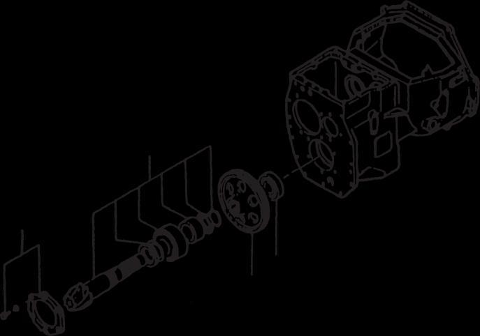
Disassembly diagram (example)
Each disassembly diagram is followed by Disassembly sequence and Suggestions disassembly.
Disassembly sequence
1 Cover, Bolt,Washer (part name)
2 Output shaft (part name)
Suggestion for disassembly (1) Output shaft removal
Symbols or abbreviations
OP Option
Clearance between cylinderand piston
A:Assembly standard
0.020 to 0.105 (0.00079 to 0.00413)
0.15 (0.0059)
B: Repair or service limit
R1/4.......................Taper pipe thread (external) 1/4 inch (formerly PT1/4)
Rc1/8 Taper pipe thread (internal) 1/8 inch (formerly PT1/8)
G1/4A Straight pipe thread (external) 1/4 inch (formerly PF1/4-A)
Rp1/8 Straight pipe thread (internal) 1/8 inch (formerly PS1/8)
GC35K-GC70K Service Manual PDF- DOWNLOAD
Group Items
GENERALINFORMATION Serial number locations, Dimensions,Technical data
COOLINGSYSTEM Fan Belt Removal, Fan Belt Inspection, Fan Belt Inspection
ELECTRICAL SYSTEM
Console box, Combination Meter, Lamp bulb specifications, Electrical system schematic
POWERTRAIN Engine and Transmission
POWERSHIFTTRANSMISSION Transmission,Controlvalve
FRONT AXLE Front wheels, Front axle, Reduction differential
REARAXLE
Rear axle, Rear wheels
BRAKESYSTEM Caliper, Brake pedal, Master cylinder
STEERING SYSTEM
Steering control valve
HYDRAULIC SYSTEM
MASTSAND FORKS
SERVICE DATA
Tank, Pump, Control valve, Lift and tilt cylinders, Flow regulator valve, Down safety valve
Simplex Mast, Duplex Mast, Triplex Mast
Inspection standards, Periodic replacement of parts, Lubrication standards, Main component weight, Tightening torque for standard bolts and nuts, Special tools
GC35K-GC70K Service Manual PDF-
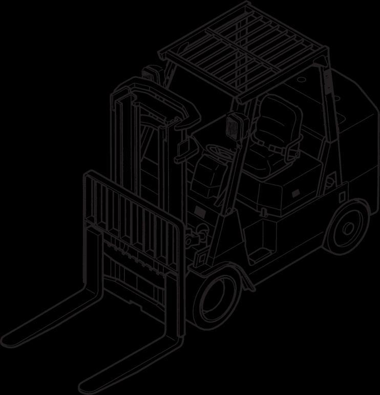
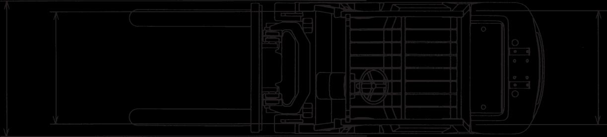
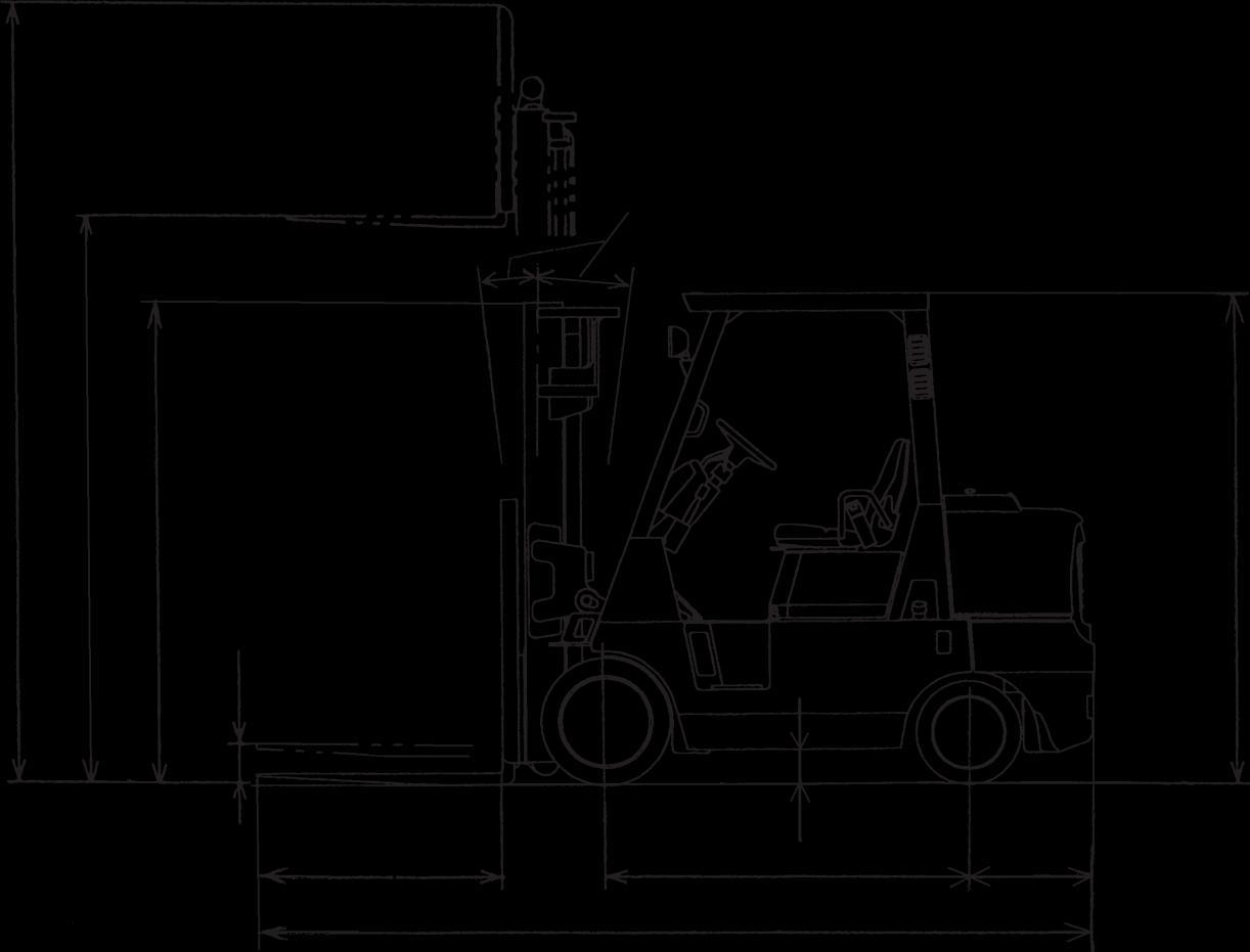
Vehicle Exterior
GENERAL INFORMATION
• This Service Manual deals with all components or systems of the Cat Lift Trucks; except for the engine and attachment, which are covered in the respective manuals.
Models
This manual applies to the following vehicle models (names).
Truck Models Transmission
GC40K
GC40K STR
Serial number
102530A
Engine mounted
GC35K 1-Speed
AT87-00001-up
AT87A-00001~10230
AT87A-10231-up
GC45K SWB
GC45K
GC55K
GC55K STR
GC70K
GC60K Automatic 2-Speed
GC70K STR
GM4.3L Gasoline Engine
AT88-00001-up
AT88A-00001~10230
AT88A-10231-up
AT89-00001-up
AT89A-00001~10230
AT89A-10231-up
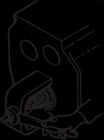
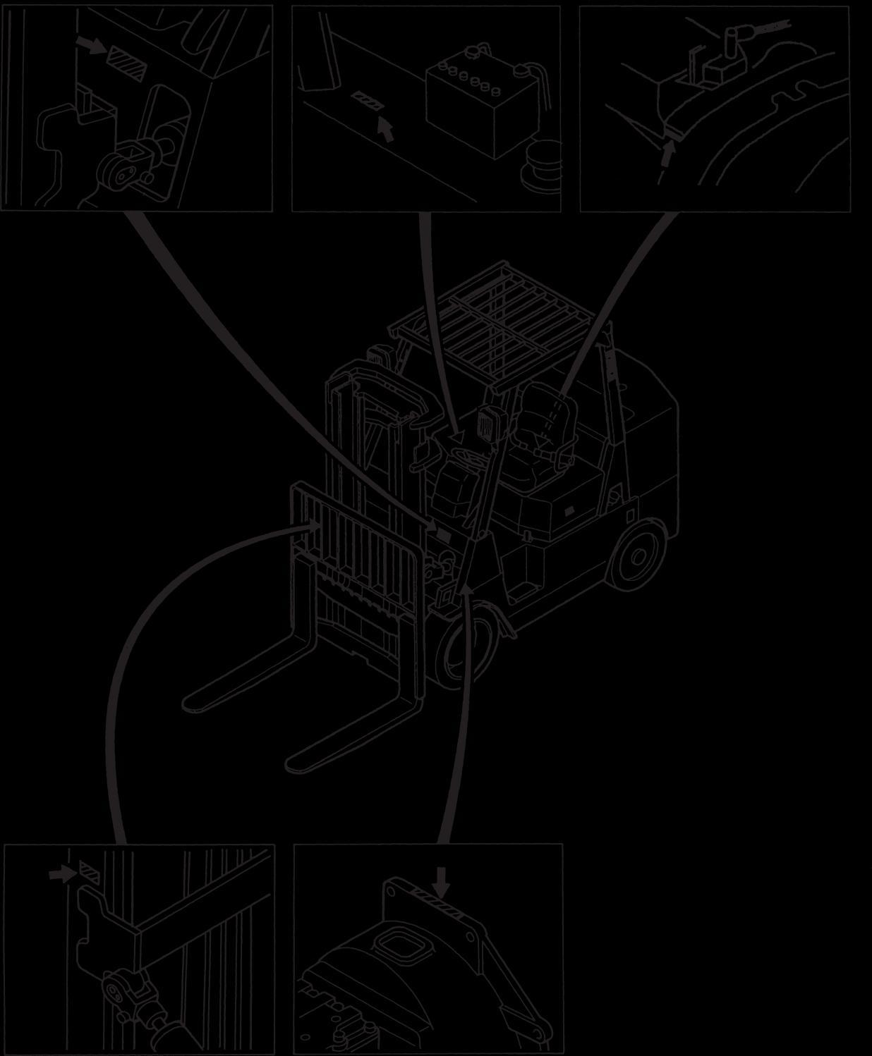
Serial Number Locations
[Chassis]
GC 55 K
Generation designator
Maximum capacity
55 :5500kg (12000lb)
Engine type
GC: gasoline engine type
[Mast]
A 55 A 33
Maximum lifting height (“33” stands for 3300mm.)
Order of the minor change (“A” for the original, “B” for the first change, “C” for the second change, and so on)
Master cylinder ID, mm (in.) 28.57 (1.125) Wheel cylinder ID, mm (in.) 31.75 (1.250)
Parking brake Type
Mechanical, mounted on wheels
Brake fluid cc (cu.in) 130 (7.9)
Brake booster
Mastervac(vacuum suspended)
Body Assembled-frametype
Gear pump Type Gear
Manufacturer’s type KFP3240 AMBAS
Rated discharge, liter(U.S.gal)/rpm
Driveline Universaljoint
Control
(in.)
Duplexmast Secondliftcylinders
Triplexmast Firstliftcylinders
Triplex
Tilt cylinders
(in.)
mm (in.)
Hydraulic tank capacity, liter (U.S.gal)
(3.937)
(4.724)
(12.1)
GC35K-GC70K Service Manual PDF- DOWNLOAD
GENERAL INFORMATION
KFP3240 AMBAS
Self-adjusting,duo-servo
317.5 (12.50)
3306310-2 (132.480.39-2)
28.57 (1.125)
31.75 (1.250)
Mechanical, mounted on wheels
130 (7.9)
Mastervac(vacuum suspended)
Assembled-frametype Gear
SPG2-48L194
98 (25.89)/2450 117.6 (31.07)/2450
Universaljoint
6000-C193
19.12 +0.5 (195 +5 ) [2773+71] 0 0 0
Variable(Adjustable)
115 (30.38)
70 (2.75)
110 (4.33)
845 (33.27)
60 (2.36)
1585 (62.40)
110 (4.33)
165 (43.56)
80 (3.15)
1650 (65)
125 (4.92)
845 (33.27) 855 (33.66)
70 (2.75) 80 (3.15)
1530 (60.24) 1495 (58.86)
100 (3.937) 110 (4.33)
120 (4.724)
52 (13.6)
139 (5.472)
69 (18.2)
GC35K-GC70K Service Manual PDF-
Truck Models
Items
Mast model CJ type
FlangeID flange back thickness
flange front thickness web thickness
Main rollers Bearing Ball bearing Diam
Side rollers Bearing Lubricated type needle roller bearing Diam width, mm (in.)
Lift chains BL834 BL1034
Fork (length width thick), mm (in.)
Fork spread (outer width), mm (in.) 1060 (41.5)
GC35K-GC70K Service Manual PDF-
GENERAL INFORMATION
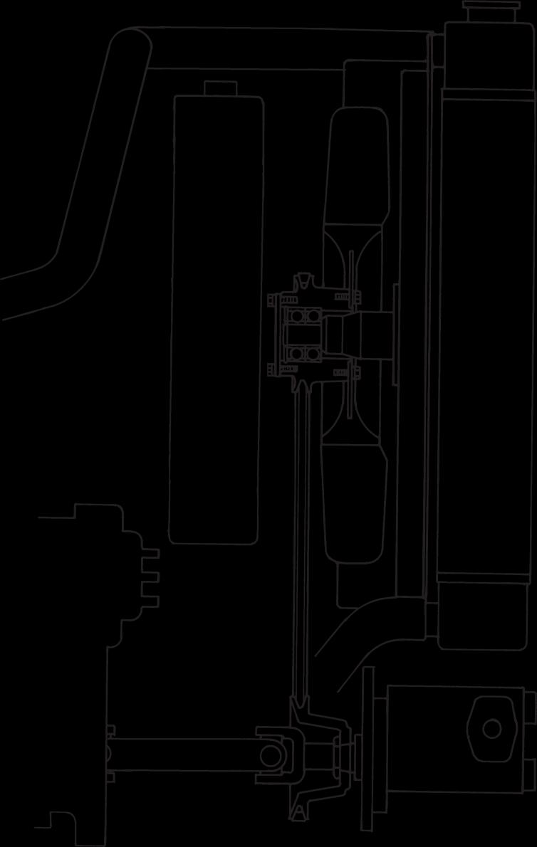
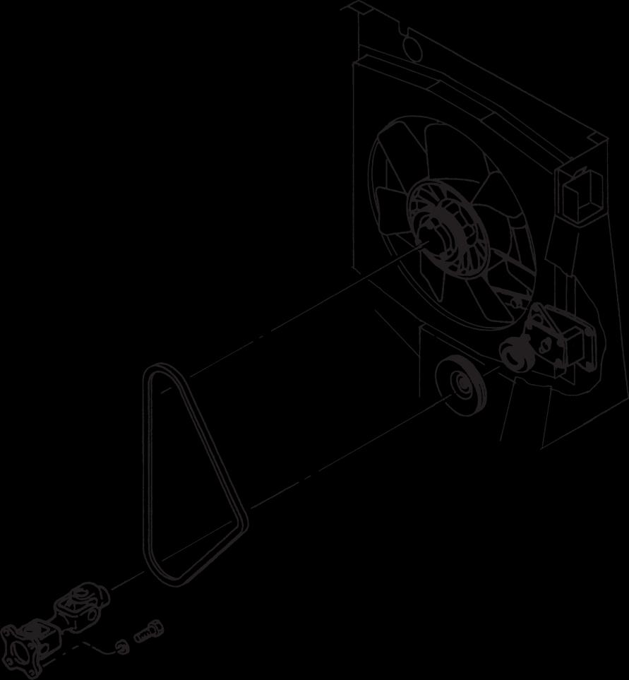
Removal and Installation
Fan Belt Removal
1. Method by removing radiator
Removal sequence
1 Universal joint
2 Tension pulley bolt (loosening only)
3 Belt
Start by: Remove the radiator cover.
207010
Suggestions for removal and installation
(1) Loosen the tension pulley bolt until the fan tension becomes loose.
(2) Forcethepulley all theway towardthefanand remove fan belt.
Installation
To install, followthereverseofremoval procedure and do the following steps:
(1) Turn the fan by hand to make sure it rotates smoothly. If its bearing is noisy, replace it.
(2) After putting the belt on the drive and driven pulleys, push it midway between the pulleys to make sure the tension pulley moves freely. Then, tighten the pulley bolt.
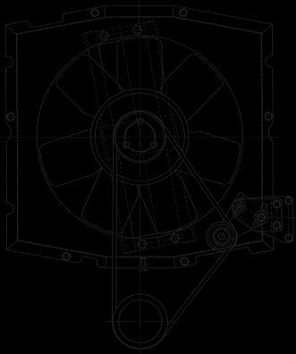
InspectionandAdjustment
Fan Belt Inspection
(1) Check to make sure the belt is free of oil, grease or other foreign matter. Replace the belt if necessary. A slightly dirty belt can be re-used by cleaning with cloth or paper. Do not attempt to clean the belt with gasoline or the like.
(2) At the time of overhauling the engine or adjusting the belt tension, closely check the belt and replace it if it is defective.
Fan BeltAdjustment
(1) Loosen the tension pulley bolt by one to two full turns with ratchet wrench.
(2) The belt will be properly tightened by the tension spring. Tighten the tension pulley bolt.
Tensionpulley bolt
207011
ELECTRICAL SYSTEM
GC35K-GC70K Service Manual PDF- DOWNLOAD
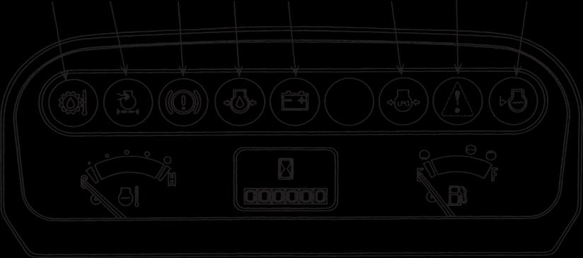
How to check indicator light bulbs The bulbs are normal if the indicator lights come ON when the starter switch key is turned to ❙ (ON) position. (The indicator lights will go OFF when the engine starts.)
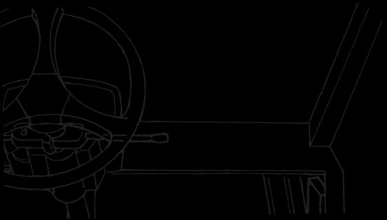
Sub Panel
The sub panel is mounted at the right front pillar of the head guard.
104794
1st speed mode/automatic mode selector switch (For 6 and 7 Ton Models as standard and others as optional)
104789
Automatic mode (1st speed 2nd speed)
1st speed mode
Select the 1st speed mode for operating in the speed-limit area [14 km/h (8.7 mph) max.], climbing or traction.
104575
Driving interlock indicator lamp
Flickers if the operator leaves the seat with the direction lever in the forward or reverse position while the engine is running.
Neutral indicator lamp
Glows when the direction lever is placed in Neutral (N) position.
ECMwarning light (GASOLINE) (IF EQUIPPED)
Glows when ECM (engine control module) is abnormal.
Consult your Cat lift truck dealer.
GC35K-GC70K
Disassembly and Reassembly
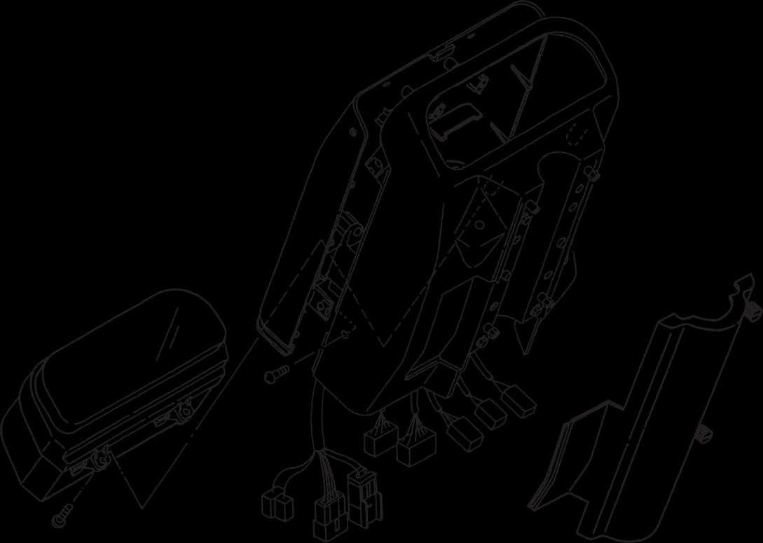
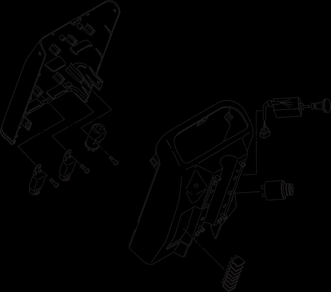
Console Box
Disassembly
1. Disconnecttheelectrical wiresat connectors1.
2. Remove screws 2 (four) securing the cover.
3. Remove screws 3 (six) and separate the front and rear panels.
To replace the instrument panel bulbs, remove screws 3 and 4.
Reassembly
To reassemble the console box, follow the reverse of disassembly procedure.
GC35K-GC70K
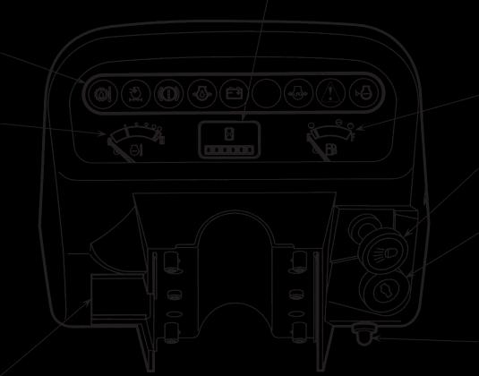
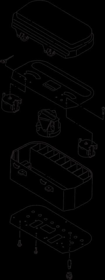
CombinationMeter
Disassembly
Sequence 1 Instrument panel
Dial
Engine coolant temperature gauge
Service hour meter
Fuel gauge
CAUTION
Be careful not to damage the printed circuit when disassembling the combination meter.
Reassembly
To reassemble the combination meter, follow the reverse of disassembly sequence.
Meter case
Printed circuit
Socket
Bulb replacement
For bulb replacement, remove the socket from the printed circuit by turning it counterclockwise. For configuration of the indicator lights, refer to “OK Monitor”.
Major Electrical Components
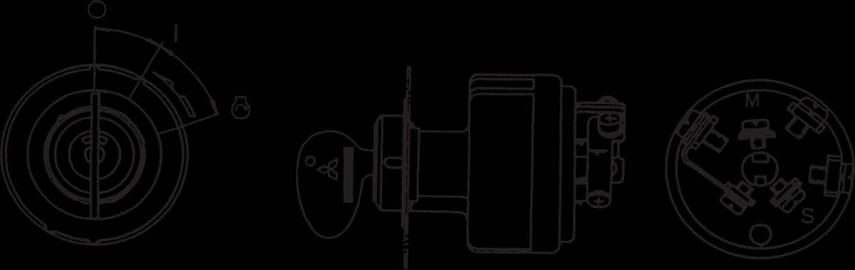
StarterSwitch (withAnti-restart Lock)
This switch has a built-in anti-restart lock, so the key cannot be turned from ❙ (ON) to (START) position while the engine is running.