- Loctite LB 8632 Silicone Lubricant (1)
- Loctite LB 8104 Silicone Lubricant (2)
- Loctite LB 8801 Silicone Lubricant (3)
- Loctite LB Superlube (4)
Note: Cleanliness is an important factor. Before assembly, all parts should be thoroughly cleaned in cleaning fluid. Allow the parts to air dry. Wiping cloths or rags should not be used to dry parts. Lint may be deposited on the parts which may cause later trouble. Inspect all parts. If any parts are worn or damaged, use new parts for replacement. Replace all seals with new seals.
1. Fasten the transmission housing to Tooling (A).
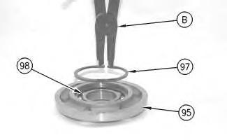
Illustration 1 g00679267
2. Install roller bearing (98) in flange (95). The roller bearing is a slip fit. Use Tooling (B) to install retaining ring (97) in the flange.
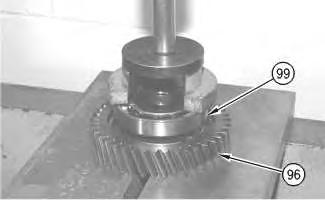
Illustration 2 g00679331
3. Use a press and a suitable sized sleeve to install bearing (99) on gear (96). Make sure that the bearing contacts with the shoulder on the gear.
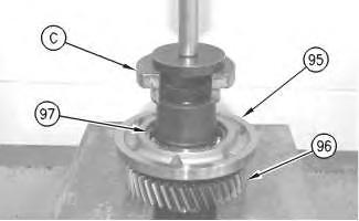
Illustration 3 g00679342
4. Use Tooling (C) and a press to install flange (95) on gear (96). Install the flange on the splined end of the gear. Install the flange with retaining ring (97) upward, as shown.
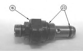
Illustration 7 g00673395
9. Install new O-ring seals (23) on valve (16).
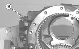
Illustration 8 g00679544
10. Install valve (16) in the transmission housing.
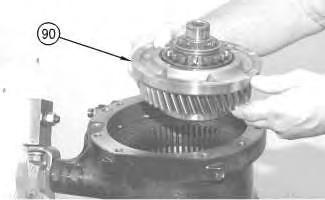
Illustration 9 g00679637
11. Use Tooling (A) to rotate the transmission housing to a vertical position, as shown. Install gear assembly (90) in the transmission housing.
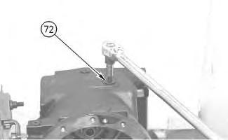
Illustration 16
g00679763
17. Install plug (72) in the transmission housing. Tighten the plug to a torque of 60 N·m (44 lb ft).
18. Use the following procedure to assemble planetary carrier (63):
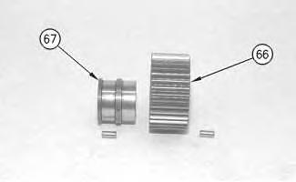
Illustration 17
g00679772
a. Apply Tooling (W) to the 46 rollers. Install the 46 rollers on bearing race (67). Install planetary gear (66) over the bearing race and the rollers.
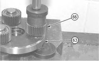
Illustration 18
g00679821
b. Use a press to install three planetary gears (66) on the planetary carrier (63).
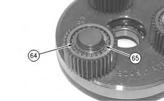
Illustration 19
g00673828
c. Install three thrust washers (64). Use Tooling (D) to install three retaining rings (65).
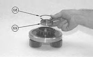
Illustration 20
g00673864
d. Reposition the planetary carrier, as shown. Install roller bearing (69) in the planetary carrier. Use Tooling (H) to install retaining ring (68).
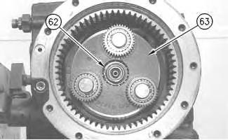
Illustration 21
g00679946
19. Heat planetary carrier (63) to a temperature of 120 °C (250 °F). Install the planetary carrier on gear assembly (90) (not shown). Allow the planetary carrier to cool. Use Tooling (D) to install retaining ring (62).
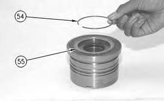
Illustration 28
g00673771
26. Install retaining ring (54) in bushing (52). Retaining ring (54) holds shaft seal (55) in position.
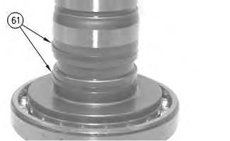
Illustration 29
g00680142
27. Apply 5P-0960 Molybdenum Grease to two retaining rings (61). Align the two retaining rings so that the retaining rings are centered on the shaft.
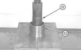
Illustration 30
g00680235
Note: Make sure that two retaining rings (61) are centered on shaft (32). If the two retaining rings are not centered correctly, the retaining rings will be damaged when shaft (32) is pressed into bushing (52).
28. Use a press to install shaft (32) in bushing (52). Install the shaft until the shoulder of the shaft contacts with the bushing.
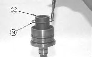
Illustration 31 g00673760
29. Use Tooling (K) to install retaining ring (51).
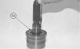
Illustration 32 g00673757
30. Reposition the shaft, as shown. Use Tooling (D) to install retaining ring (50).
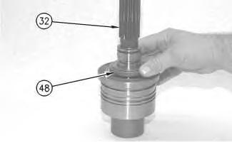
Illustration 33 g00680272
31. Install plate (48) on shaft (32).
Illustration 40
g00680512
Note: Make sure that friction discs (40) and clutch plates (41) are dried prior to assembly.
e. Install friction discs (40) and clutch plates (41) on gear (43). Install the friction discs and the clutch plates in alternating order. Start with a friction disc and end with a clutch plate.
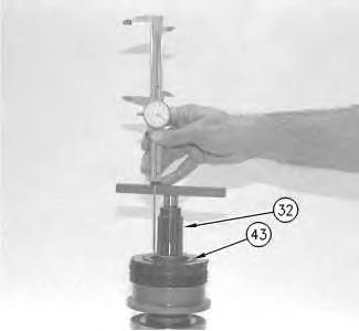
Illustration 41
g00680527
f. Position a straight edge on the end of shaft (32), as shown. Use a caliper to measure the distance from the end of the shaft to the top of gear (43). Record this dimension as dimension (V).
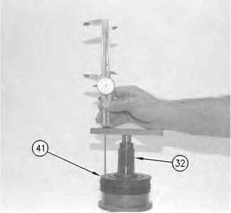
Illustration 42
g00680536
g. Position a straight edge on the end of shaft (32), as shown. Use a caliper to measure the distance from the end of the shaft to the face of the last clutch plate (41). Record this dimension as dimension (W).
h. Subtract dimension (V) from dimension (W). The difference is value (B). Value (B) in transmissions with ten plates must be 10.70 ± 0.10 mm (.421 ± .004 inch). Value (B) in transmissions with 11 plates must be 7.90 ± 0.10 mm (.311 ± .004 inch). If value (B) is not correct, change the thickness of the last clutch plate and the last friction disc. Refer to the Parts Manual for further information.
33. Use the following procedure to determine the end play of gear (43) and gear (34):
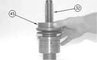
Illustration 48 g00680731
40. Install flange (45) on shaft (32). Position the flange on the belleville springs.
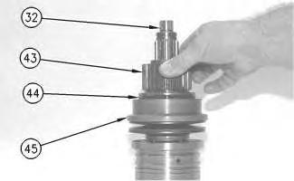
Illustration 49 g00680736
41. Install a new backup ring (44) on gear (43). Install the backup ring with the sealing lip toward flange (45). Apply 5P-0960 Molybdenum Grease on backup ring (44).
42. Install gear (43) on shaft (32).
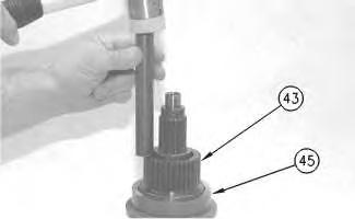
Illustration 50 g00680477
43. Use a hammer and a brass punch to position gear (43) in flange (45). Tap around the gear to seat the gear correctly in the flange.

NOTE: If there is no response to click on the link above, please download the PDF document first and then clickonit.
e. Reduce the pressure to 1998 kPa (290 psi). The clutch should not rotate at this pressure. If the clutch rotates at this pressure, replace belleville springs (46).
f. Remove Tooling (P). Remove Tooling (N).
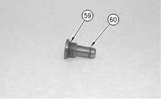
Illustration 62
g00673800
53. Install a new O-ring seal (59) and a new O-ring seal (60) on the throttle valve.
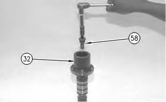
Illustration 63
g00673798
54. Install throttle valve (58) in the end of shaft (32).
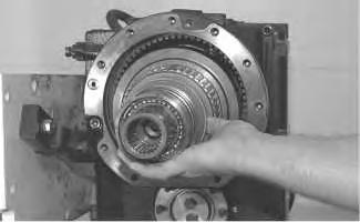
Illustration 64
g00673461
55. Install the clutch assembly in the transmission housing.