Product: DOWNLOAD SERVICE MANUAL VIBRATORY COMPACTOR
Model: CB-335E VIBRATORY COMPACTOR C5J
Configuration: CB-334E,CB-335E Vibratory Compactor C5J00001-UP (MACHINE) POWERED BY 3013C Engine
Disassembly and Assembly
3003, 3013, 3014 and 3024 Engines for Caterpillar Built Machines
Media Number -SENR5027-05
Publication Date -01/05/2005
Engine Oil Pump - Remove
SMCS - 1304-011
Removal Procedure
Start By:
Date Updated -16/05/2005
A. Remove the engine oil pan. Refer to Disassembly and Assembly, "Engine Oil Pan - Remove and Install".
B. Remove the front housing. Refer to Disassembly and Assembly, "Housing (Front)Remove".
NOTICE
Keep all parts clean from contaminants.
Contaminants may cause rapid wear and shortened component life.
NOTICE
If the front housing is not installed, do not turn the crankshaft. Damage to the engine may occur.
NOTICE
Care must be taken to ensure that fluids are contained during performance of inspection, maintenance, testing, adjusting and repair of the product. Be prepared to collect the fluid with suitable containers before opening any compartment or disassembling any component containing fluids.
Refer to Special Publication, NENG2500, "Caterpillar Dealer Service Tool Catalog" for tools and supplies suitable to collect and contain fluids on Caterpillar products.
Dispose of all fluids according to local regulations and mandates.
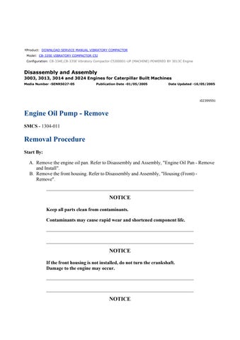
Engine Oil Pump
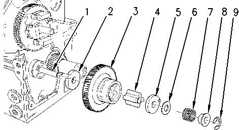
Illustration 1
Personal injury can result from being struck by parts propelled by a released spring force.
Make sure to wear all necessary protective equipment.
Follow the recommended procedure and use all recommended tooling to release the spring force.
1. Remove retaining ring (9) that retains idler gear (3) on idler hub (1)
2. Remove the following items from idler hub (1) :
◦ Collar (8)
◦ Spring (7)
◦ Shim (6)
◦ Oil pump cover (5)
◦ Inner rotor (4)
3. Remove idler gear (3) from idler hub (1) .
4. Remove thrust washer (2) from idler hub (1)
5. Inspect all the components for wear or damage. If components are worn or damaged, use new parts for replacement.
Note: Refer to Specifications, "Engine Oil Pump" for more information.
6. If the engine oil pump has excessive buildup of sludge, inspect the oil strainer. The oil strainer can be removed by using the following procedure:
a. Remove the engine oil pan. Refer to Disassembly and Assembly, "Engine Oil PanRemove and Install".
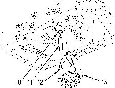
Illustration 2
b. Remove bolts (12) and oil strainer (13) from the cylinder block. Inspect the oil strainer for damage. If the oil strainer is damaged, use a new part for replacement.
c. Remove tube assembly (11) from the cylinder block.
d. Remove O-ring seal (10) from the tube assembly. Inspect the O-ring seal for wear or damage. If the O-ring seal is worn or damaged, use a new part for replacement.
Idler Hub
Table 1
Required Tools
Tool Part Number Part Description Qty
A 1P-0074 Slide Hammer Puller 1
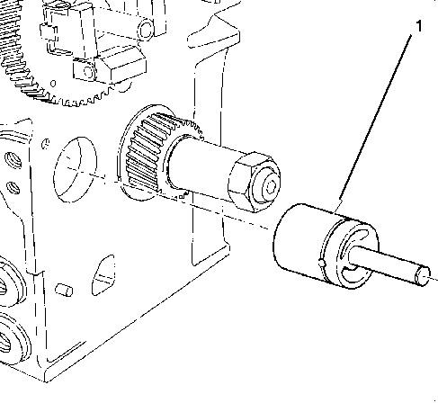
Illustration 3 g01037604
1. Use Tooling (A) to remove idler hub (1) from the cylinder block.
Product: VIBRATORY COMPACTOR
Model: CB-335E VIBRATORY COMPACTOR C5J
Configuration: CB-334E,CB-335E Vibratory Compactor C5J00001-UP (MACHINE) POWERED BY 3013C Engine
Disassembly and Assembly
3003, 3013, 3014 and 3024 Engines for Caterpillar Built Machines
Media Number -SENR5027-05
Engine Oil Pump - Install
SMCS - 1304-012
Installation Procedure
Table 1
Required Tools
B 8T-5096 Dial Indicator Test Group 1
C (1) 256-4864 Alignment Tool
C (2) 241-4232 Alignment Tool 1
D 1S-0257 Ball Peen Hammer 1
E 1P-0808 Multipurpose Grease 1
( 1 ) 3003 engines
( 2 ) 3013, 3014 and 3024 engines
NOTICE
Keep all parts clean from contaminants.
Contaminants may cause rapid wear and shortened component life.
-16/05/2005
i03121381
NOTICE
If the front housing is not installed, do not turn the crankshaft.
Damage to the engine may occur.
Idler Hub
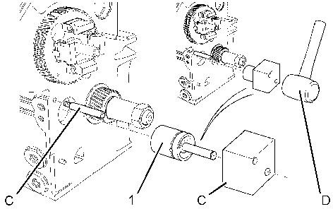
Illustration 1 g01198501
1. Use Tooling (C) and Tooling (D) to install idler hub (1) in the cylinder block.
Engine Oil Pump
Illustration 2 g00825411
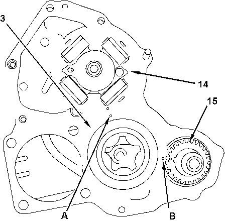
Illustration 3 g01037617
Improper assembly of parts that are spring loaded can cause bodily injury.
To prevent possible injury, follow the established assembly procedure and wear protective equipment.
1. Apply Tooling (E) to the faces of inner rotor (4) and to the vanes of idler gear (3) .
2. Align Timing Marks (A) and (B) that are on idler gear (3) with the respective timing marks on gears (14) and (15) . Install idler gear (3) on idler hub (1) .
3. Install inner rotor (4) in idler gear (3) .
Personal injury can result from the release of the spring force.
The drive shaft, the piston, and the drive gear are under spring force.
Use a press to slowly release the spring force before the components are removed.
4. Install the following items on idler hub (1) :
◦ Oil pump cover (5)
◦ Shim (6)
◦ Spring (7)
◦ Collar (8)
5. Install retaining ring (9) on idler hub (1)
6. Use Tooling (B) in order to measure the end play of the engine oil pump. Refer to Specifications, "Engine Oil Pump".
7. If the oil strainer was removed, use the following procedure for installation:
End By:
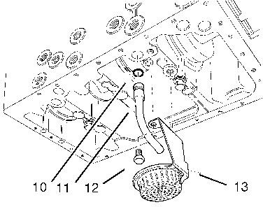
Illustration 4 g01037619
a. Install O-ring seal (10) on tube assembly (11) .
b. Install tube assembly (11) in the cylinder block.
c. Install oil strainer (13) on the cylinder block and tighten bolts (12) to a torque of 11 N·m (97 lb in).
a. Install the front housing. Refer to Disassembly and Assembly, "Housing (Front) - Install".
b. Install the engine oil pan. Refer to Disassembly and Assembly, "Engine Oil Pan - Remove and Install".