Product: EXCAVATOR


Model: 349E L VG EXCAVATOR KFX
Configuration: 349E L Excavators KFX00001-UP (MACHINE) POWERED BY C13 Engine
Disassembly and Assembly
349E Excavator Machine Systems
Media Number -KENR9848-04
Travel Motor - Disassemble
SMCS - 4351-015
Disassembly Procedure
Start By:
1. Drain the travel motor. Previous Screen
Table 1
i04243909
a. Remove the travel motor.
1
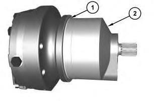
2. Remove O-ring seal (1) from motor housing (2).
2
Personal injury can result from being struck by parts propelled by a released spring force.
Make sure to wear all necessary protective equipment.
Follow the recommended procedure and use all recommended tooling to release the spring force.
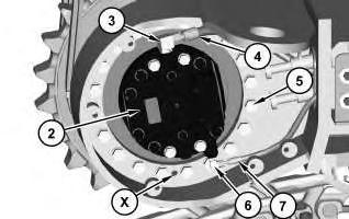
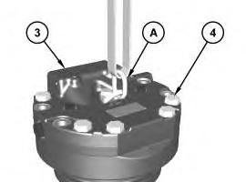
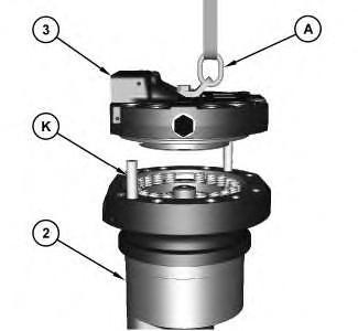
3. Attach Tooling (A) onto head assembly (3). Remove bolts (4). Use Tooling (A) and a suitable lifting device to remove head (3). The weight of head assembly (3) is approximately 40 kg (90 lb).
3
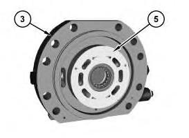
4. Remove plate (5) from head (3).
4
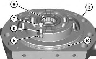
5. Remove bearing (6) from head assembly (3).
6. Remove orifice (7), spring (8), and ball (9).
7. Remove O-ring seal (10) from head assembly (3).
5
Personal injury can result from being struck by parts propelled by a released spring force.
Make sure to wear all necessary protective equipment.
Follow the recommended procedure and use all recommended tooling to release the spring force.
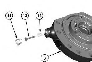
8. Remove adapter (11), spool (12), and spring (13) from head assembly (3).
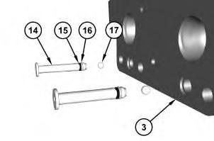
Illustration 6
9. Use Tooling (B) in order to remove retainers (14) from head assembly (3).
10. Remove O-ring seals (16) and backup rings (15) from adapters (14).
11. Remove balls (17) from head assembly (3).
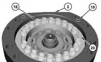
Illustration 7
g02419577
12. Remove springs (18) from brake housing (20).
13. Remove O-ring seals (19) from motor housing (2).
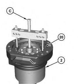
Illustration 8
g02420880
14. Use Tooling (C) in order to remove brake housing (20) from motor housing (2).

Illustration 9
g02419659
15. Remove backup ring (21) and O-ring seal (22) from brake piston (20).
16. Remove O-ring seal (23) and backup ring (24) from brake piston (20).
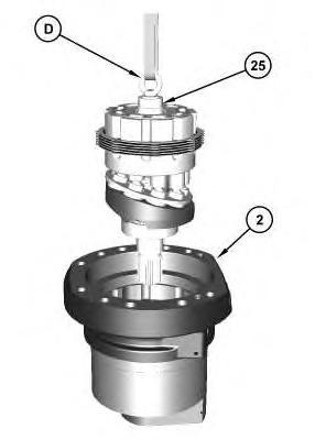
Illustration 10 g02419858
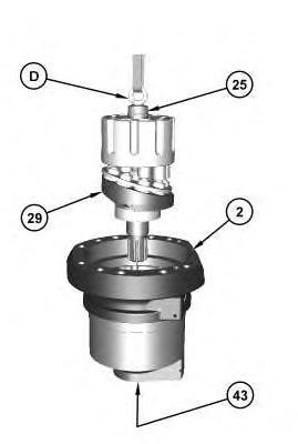
17. Attach Tooling (D) to shaft assembly (25).
18. Use Tooling (D) and a suitable lifting device in order to lift the rotating group from motor housing (2). The weight of the rotating group is approximately 30 kg (65 lb).
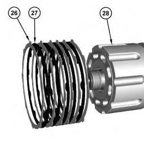
Illustration 11 g02420501
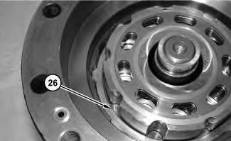
19. Remove plates (26) and friction disks (27) from barrel assembly (28).
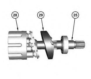
Illustration 12
g02420544
20. Remove barrel assembly (28) and swashplate (29) from shaft assembly (25).
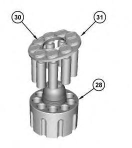
Illustration 13
g02420578
21. Remove plate (31) and pistons (30) from barrel assembly (28).
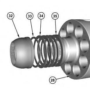
Illustration 14
g02420596
22. Remove bearing (32), thin shim (33), Belleville washers (34), and barrel spacer (35) from barrel assembly (28).
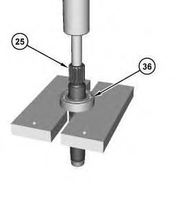
Illustration 15
g02420937
23. Use a suitable press in order to remove bearing (36) from shaft assembly (25).
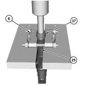
Illustration 16
24. Use Tooling (E) and a suitable press in order to remove inner race (37) from shaft assembly (25).
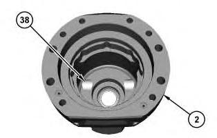
Illustration 17
g02420998
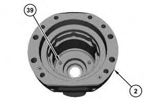
Illustration 18
g02421000
25. Remove keys (38) and pins (39) from motor housing (2).
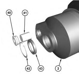
Illustration 19 g02421056
26. Remove plug (40) and the O-ring seal. Remove actuator piston (41).
27. Remove retaining ring (42) and seal (43) from motor housing (2).
Copyright 1993 - 2020 Caterpillar Inc. All Rights Reserved. Private Network For SIS Licensees. Fri Oct 2 10:47:01 UTC+0800 2020
Previous Screen
Product: EXCAVATOR
Model: 349E L VG EXCAVATOR KFX


Configuration: 349E L Excavators KFX00001-UP (MACHINE) POWERED BY C13 Engine
Disassembly and Assembly
349E Excavator Machine Systems
Media Number -KENR9848-04
Publication Date -01/10/2012
Travel Motor - Assemble
SMCS - 4351-016
Specifications
Date Updated -23/10/2012
i06563923
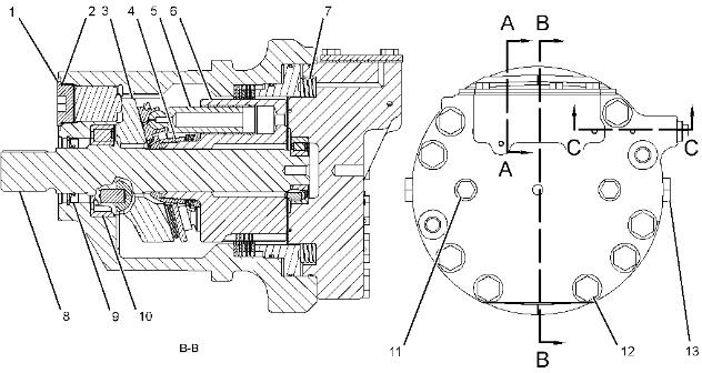
Illustration 1
NOTICE
To prevent damage to the motor, the case must be filled with clean hydraulic oil at least to the fill port before operation.
g03845362
Table 1
Specification for 390-1088 Travel Motor Gp
Item Qty Part
1 1 5P-7684 Plug Torque to 430 ± 40 N·m (317 ± 30 lb ft).
2 1
6K-6307 ORing Seal Lubricate with 1U-6396 O-Ring Assembly Compound. - - -
Before assembly, lubricate the sliding surfaces of the cam plate (3), the hold-down (4), the pistons (5), the barrel (6) and the shaft (8) lightly with clean hydraulic oil.
7 20 124-1561Brake Spring
9 1
Length under test force is 19.0 mm (0.75 inch). Test force is 425 ± 43 N (96 ± 10 lb). Free length after test is 22.06 mm (0.869 inch).
6V-3382 Lip Type Seal Apply blue Loctite 243 to the outside diameter.
10 1 118-5805 SpecialRace Bearing
11 2
Install the snap ring of the special race bearing toward the shaft flange.
9S-4185 ORing Plug Torque to 82 ± 8 N·m (60 ± 6 lb ft).
12 6 8T-4187 Bolt Torque to 530 ± 70 N·m (391 ± 52 lb ft).
13 2 9S-4183 ORing Plug Torque to 190 ± 20 N·m (140 ± 15 lb ft).
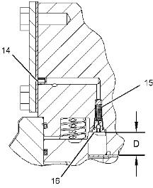
Illustration 2 g03845364
Section A-A Table 2
14 2
1T-0936 Pipe Plug Install in the orifice toward the head surface or below the head surface.
15 1 124-1554 Spring
Length under test force is 15 mm (0.6 inch).
Test force is 15.0 ± 2.0 N (3.4 ± 0.4 lb).
Free length after test is 16.15 mm (0.636 inch).
Depth from the head and interface of the port plate is 20.0 ± 0.2 mm (0.79 ± 0.01 inch).
16 1 195-4456Orifice Plug Torque to 7 ± 1 N·m (62 ± 9 lb in).
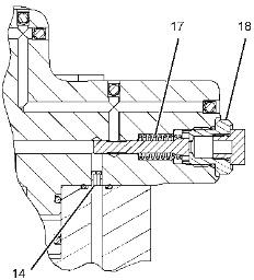
Illustration 3
g03845365 Section C-C
Table 3
Item Qty Part
17 1 230-5483 Spring
Specification Description
Length under test force is 25 mm (1.0 inch). Test force is 60.0 ± 8.0 N (13.5 ± 1.8 lb). Free length after test is 35 mm (1.4 inch).
18 1 087-4786 Adapter Torque to 115 ± 10 N·m (85 ± 7 lb ft).
Assembly Procedure
4

Illustration 4 g02421056
1. Lubricate actuator piston (41) with the oil that is being used. Install actuator piston (41) into housing (2). Apply Tooling (F) onto O-ring seal of plug (40). Install plug (40) into motor housing (2).Tighten plug (42) to a torque of 430 ± 40 N·m (315 ± 30 lb ft).
2. Apply Tooling (G) onto outside diameter of seal (43). Use Tooling (H) to install seal (43). Install retaining ring (42).
Illustration 5 g02421000
Illustration 6
g02420998
3. Install pins (39) and keys (38) into motor housing (2).

Illustration 7
g02421876
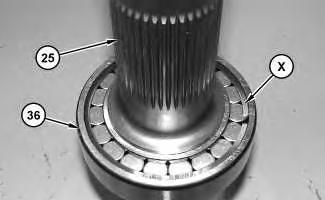
Illustration 8
g02421958
4. Use a suitable press to install bearing (36) and bearing (37) onto shaft assembly (25). Bearing (36) must be installed with Retaining Clip (X) toward the barrel assembly.
9 g02420596
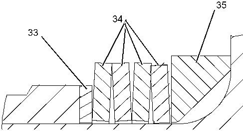
Illustration 10 g02423556
Illustration 11
6. Install pistons (30) and plate (31) onto barrel assembly (28).
Illustration 12
7. Install swashplate (29) and barrel assembly (28) onto shaft assembly (25).
13
8. Use Tooling (D) and a suitable lifting device to install the rotating group into motor housing (2). The weight of the rotating group is approximately 30 kg (65 lb).
Note: Align the notches of swashplate (29) with the keys in the motor housing (2).
Note: Protect shaft seal (43) from damage by covering the splines on shaft assembly (25) with heat shrink tubing.
14
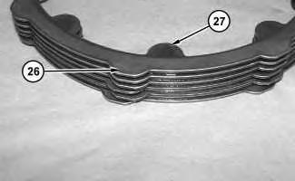
Illustration 15
9. Install plates (26) and friction discs (27). Start with plate (26). Alternate between plates (26) and friction discs (27) with plates (26) on the top and the bottom.
Illustration 16
g02419659
10. Install backup ring (21) and O-ring seal (22) onto brake piston (20).
11. Install backup ring (24) and O-ring seal (23) onto brake piston (20).
Illustration 17
12. Install O-ring seals (19) onto motor housing (2). Install springs (18) onto brake piston (20).

18
13. Install balls (17), backup rings (15), O-ring seals (16), and retainers (14) into head assembly (3).
19
Improper assembly of parts that are spring loaded can cause bodily injury.
To prevent possible injury, follow the established assembly procedure and wear protective equipment.
14. Install spring (13), spool (12), and adapter (11). Tighten adapter (11) to a torque of 115 ± 10 N·m (85 ± 7 lb ft).
Illustration 20
15. Install ball (9), spring (8), and orifice (7). Tighten orifice (7) to a torque of 7 ± 1 N·m (62 ± 9 lb in).
16. Install bearing (6) and O-ring seal (10) onto head assembly (3).
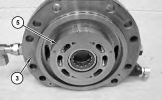
Illustration 21
g02001974
Illustration 22
g02419358
17. Apply Tooling (K) to the back side of plate (5) to hold plate (5) in place during assembly. Install plate (5) to head assembly (3).
24
Improper assembly of parts that are spring loaded can cause bodily injury.
To prevent possible injury, follow the established assembly procedure and wear protective equipment.
18. Install Tooling (K) onto motor housing (2). Use Tooling (A) and a suitable lifting device to install head assembly (3) onto motor housing (2).The weight of the head (3) is approximately 40 kg (90 lb). Remove Tooling (A) and Tooling (D). Install bolts (4). Tighten bolts (4) to a torque of 530 ± 70 N·m (390 ± 50 lb ft).
Illustration 25
19. Install O-ring seal (1) onto motor housing (2).
End By:
a. Install the travel motor.
Copyright 1993 - 2020 Caterpillar Inc. All Rights Reserved. Private Network For SIS Licensees.
Fri Oct 2 10:47:57 UTC+0800 2020
Previous Screen
Product: EXCAVATOR
Model: 349E L VG EXCAVATOR KFX
Configuration: 349E L Excavators KFX00001-UP (MACHINE) POWERED BY C13 Engine
Disassembly and Assembly
349E Excavator Machine Systems
Media Number -KENR9848-04
Publication Date -01/10/2012
Date Updated -23/10/2012
Final Drive and Travel Motor - Remove and Install
SMCS - 4050; 4351
Removal Procedure
Table 1
Required Tools
Tool
A 1U-9200 Lever Puller Hoist 1
B 439-3941 Link Brackets 2
C - Loctite 243 -
Hydraulic oil pressure can remain in the hydraulic system after the engine has been stopped. Serious injury can be caused if this pressure is not released before any service is done on the hydraulic system.
Make sure all of the work tools have been lowered to the ground, and the oil is cool before removing any components or lines. Remove the oil filler cap only when the engine is stopped, and the filler cap is cool enough to touch with your bare hand.
i07186913
1. Refer to Operation and Maintenance Manual, "Final Drive Oil - Change" for the correct draining and filling procedures.
1
2. Release the track tension. Refer to Operation and Maintenance Manual, "Track Adjustment - Adjust".
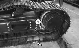
3. Start the machine. Position track roller (1) on suitable cribbing. Position pin to separate the track above the final drive.
4. Separate the track.
5. Remove the counterbalance valve.
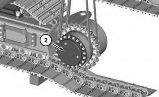
2