1. Engine speed/timing sensor
• No signal from speed/timing sensor will prevent engine operation
• Check speed/timing sensor output signal
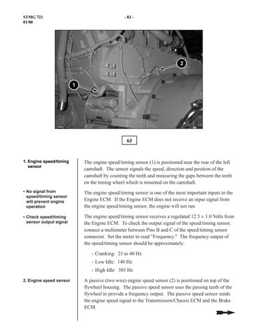
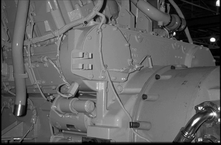
The engine speed/timing sensor (1) is positioned near the rear of the left camshaft. The sensor signals the speed, direction and position of the camshaft by counting the teeth and measuring the gaps between the teeth on the timing wheel which is mounted on the camshaft.
The engine speed/timing sensor is one of the most important inputs to the Engine ECM. If the Engine ECM does not receive an input signal from the engine speed/timing sensor, the engine will not run.
The engine speed/timing sensor receives a regulated 12.5 ± 1.0 Volts from the Engine ECM. To check the output signal of the speed/timing sensor, connect a multimeter between Pins B and C of the speed/timing sensor connector. Set the meter to read "Frequency." The frequency output of the speed/timing sensor should be approximately:
- Cranking: 23 to 40 Hz
- Low Idle: 140 Hz
- High Idle: 385 Hz
2. Engine speed sensor
A passive (two wire) engine speed sensor (2) is positioned on top of the flywheel housing. The passive speed sensor uses the passing teeth of the flywheel to provide a frequency output. The passive speed sensor sends the engine speed signal to the Transmission/Chassis ECM and the Brake ECM.
The signal from the passive speed sensor is used for the Automatic Retarder Control (ARC) engine control speed.
The output signal of the passive speed sensor can also be checked by connecting a multimeter between the two pins of the speed sensor connector and setting the meter to read frequency
NOTE: Turn ON the engine shutdown switch (see Slide No. 23) during the cranking test to prevent the engine from starting. The cranking speed and frequency output will vary depending on weather and machine conditions (battery charge). When viewing engine speed in the ET status screen, cranking speed should be between 100 and 250 rpm.
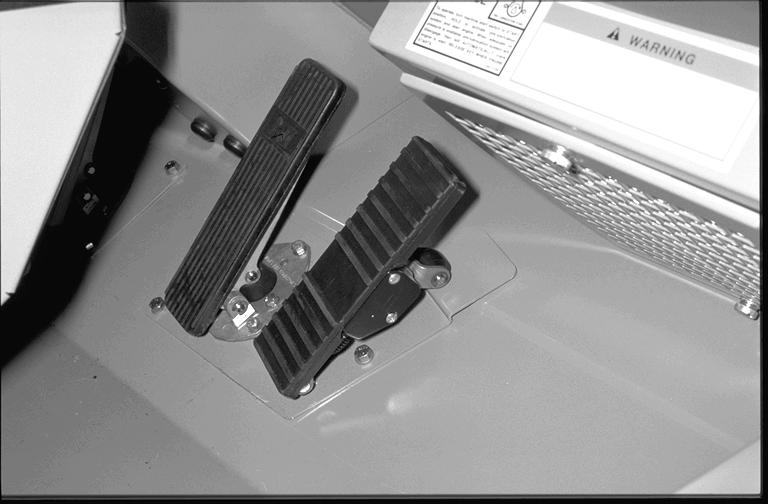
• Throttle position sensor (arrow)
• Throttle position sensor signal is PWM
The throttle position sensor (arrow) provides the desired throttle position to the Engine ECM. If the Engine ECM detects a fault in the throttle position sensor, the throttle back-up switch (see Slide No. 46) can be used to increase the engine speed to 1300 rpm.
The throttle position sensor receives a regulated 8.0 ± 0.5 Volts from the Engine ECM. The throttle position sensor output signal is a Pulse Width Modulated (PWM) signal that varies with throttle position and is expressed as a percentage between 0 and 100%.
• Check throttle position sensor output signal
• Throttle position sensor must be set with ET
To check the output signal of the throttle position sensor, connect a multimeter between Pins B and C of the throttle position sensor connector. Set the meter to read "Duty Cycle." The duty cycle output of the throttle position sensor should be:
- Low Idle: 16 ± 6%
- High Idle: 85 ± 4%
NOTE: The throttle position sensor setting can be changed in the Engine ECM using the Configuration screen of ET. Two settings are available: 10% to 50% Throttle and 10% to 90% Throttle. The 777D Update truck must be set to the 10% to 90% Throttle setting.