Chapter 1
GENERAL INFORMATION
TO THE OWNER
Your machine has been designed and built to the highest standards of quality. It conforms to all current safety regulations. See Official documents. However, the risk of accidents can never be completely excluded. That is why it is essential to observe elementary safety rules and precautions.
Read this manual carefully, paying particular attention to the instructions concerning safety, operation and maintenance so as to avoid the risk of injury while operating or servicing the machine.
The standard attachments and tools of this machine are designed to carry out all kinds of earth moving and rehandling operations. If you want to use this machine to handle a load (pipes, culverts, framework, etc.), make sure that it is designed to carry out this kind of work. For this type of application, the machine must be equipped with safety valves, an overload indicator, a load handling chart corresponding to the type of machine and its attachment and a load fixing point. All legal requirements must also be strictly observed.
Do not use this machine for any application or purpose other than those described in this manual. If the machine is to be used for work involving the use of special attachments, accessories or equipment, consult your Dealer in order to make sure that any adaptations or modifications made are in keeping with the machine's technical specifications and with prevailing safety requirements.
Any modification or adaptation which is not approved by the manufacturer may invalidate the machine's initial conformity with safety requirements.
CHAPTER 1 - GENERAL INFORMATION 1-1 6-34551NAIssued 8-04 Bur
CT02C001FX
Figure 1
HYDRAULIC CRAWLER EXCAVATORS SERIES CX75SR, CX80 AND CX135SR
The machine must undergo regular inspections, the frequency of which varies according to the type of use. Consult your Dealer.
Before permitting a new operator on this machine, make sure:
1.That the operator has received the necessary training on how to operate the machine correctly and safely in one of our training centres or from an approved organization.
2.That the operator has read and understood the instructions given in this manual.
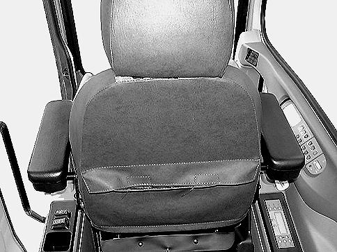
Always keep this manual in the operator's compartment (in the seat back, behind the operator's seat). Make sure it is always complete and in good condition. If you wish to obtain extra copies, or copies in languages other than that of the country of use, consult your Dealer.
Your Dealer is at your disposal for any further information. He will also provide any after-sales service you may require, and genuine CASE spare parts, your guarantee of quality and match.
CHAPTER 1 - GENERAL INFORMATION 1-2 Issued 8-04 Bur6-34551NA
MAIN COMPONENTS
The CX75SR, CX80 and CX135SR are fully hydraulic machines. They consist of an undercarriage fitted with tracks and a turntable bearing which supports the upperstructure frame. The upperstructure frame supports the attachment, at the front end of the machine, plus the engine, hydraulics and cab. When the operator works the controls, the engine-driven pump delivers hydraulic fluid to the control valves. The control valves distribute the hydraulic fluid to the various cylinders and motors concerned. A cooling system maintains the hydraulic fluid at normal operating temperature.
CHAPTER 1 - GENERAL INFORMATION 1-3 6-34551NAIssued 8-04 Bur
MACHINE COMPONENTS CT02C001
Figure 2
1.CAB/OPERATOR'S
CYLINDER17.IDLER WHEELS 2.UPPERSTRUCTURE10.BACKHOE BUCKET18.TRACKS 3.UNDERCARRIAGE11.BACKHOE BUCKET CYLINDER19.HYDRAULIC RESERVOIR 4.STEPS12.ENGINE COMPARTMENT20.FUEL TANK 5.ACCESS HANDLES13.COUNTERWEIGHT21.DOZER BLADE (IF EQUIPPED) 6.BOOM14.UPPER ROLLERS22.DOZER BLADE CYLINDERS (IF EQUIPPED) 7.BOOM CYLINDERS15.LOWER ROLLERS 8.ARM16.TRAVEL REDUCTION GEARS 6 1 12 10 7 8 11 2 9 13 16 14 18 17 15 4 3 22 21 19 20 5 5
COMPARTMENT9.ARM
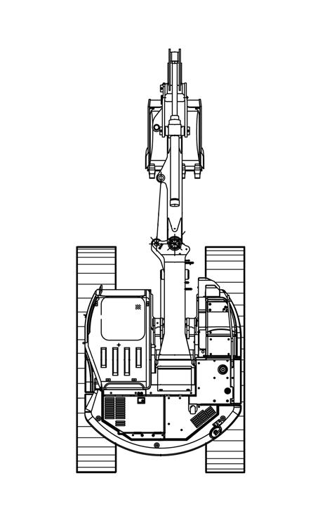
The terms Right-hand, Left-left, Front, and Rear are used in this manual to indicate the sides as they are seen from the operator's seat when the cab is over the idler wheels.
The illustration below shows the machine in normal TRAVEL position. In normal TRAVEL position, the cab is over the idler wheels. The travel reduction gears are at the rear of the upperstructure.
CHAPTER 1 - GENERAL INFORMATION 1-4 Issued 8-04 Bur6-34551NA
RIGHT, LEFT, FRONT AND REAR OF THE MACHINE
CT02D269
Figure 3
1.FRONT
2.REAR
3.RIGHT-HAND SIDE
4.LEFT-HAND SIDE
5.TRAVEL REDUCTION GEARS
6.IDLER WHEELS
1 6 6 3 4 5 5 2
IDENTIFICATION NUMBERS
TYPE, SERIAL NUMBER AND YEAR OF MANUFACTURE
When ordering parts, obtaining information or assistance, always supply your Dealer with the type and serial number of your machine or accessories. Write the following in the spaces below: The type, serial number and year of manufacture of your machine, accessories and the serial numbers of the various hydraulic and mechanical components.
CHAPTER 1 - GENERAL INFORMATION 1-5 6-34551NAIssued 8-04 Bur
Machine
Figure 4
CX75SR, CX80 Engine
CT02C062
Figure 5
CX135SR Engine
CT02C050
COMPONENT SERIAL NUMBERS Hydraulic pump................................................................................................................. Swing reduction gear........................................................................................................... Travel reduction gears......................................................................................................... Travel control valve...................................................................................................................................................... Attachment control valve............................................................................................................................................. Swing control valve............................................................................................................
Figure 6
➤ Make and Model ➤ Serial Number
CX75SR, CX80 Engine
➤ Make and Model ➤ Serial Number
CX135SR Engine
CHAPTER 1 - GENERAL INFORMATION 1-6 Issued 8-04 Bur6-34551NA NOTES
Chapter
CHAPTER 2 - SAFETY, DECALS,
2-1 Issued 8-04 Bur6-34551NA
AND HAND SIGNALS
OF CONTENTS SAFETY RULES . . . . . . . . . . . . . . . . . . . . . . . . . . . . . . . . . . . . . . . . . . . . . . . . . . . . . . . . . . . . . . . . . . . . . . . . . . 2-3 PERSONAL SAFETY . . . . . . . . . . . . . . . . . . . . . . . . . . . . . . . . . . . . . . . . . . . . . . . . . . . . . . . . . . . . . . . . . . . . . . 2-3 SAFETY AREA . . . . . . . . . . . . . . . . . . . . . . . . . . . . . . . . . . . . . . . . . . . . . . . . . . . . . . . . . . . . . . . . . . . . . . . . . . . 2-3 UTILITY SAFETY . . . . . . . . . . . . . . . . . . . . . . . . . . . . . . . . . . . . . . . . . . . . . . . . . . . . . . . . . . . . . . . . . . . . . . . . . 2-3 OPERATOR PRECAUTIONS . . . . . . . . . . . . . . . . . . . . . . . . . . . . . . . . . . . . . . . . . . . . . . . . . . . . . . . . . . . . . . . 2-4 Personnel . . . . . . . . . . . . . . . . . . . . . . . . . . . . . . . . . . . . . . . . . . . . . . . . . . . . . . . . . . . . . . . . . . . . . . . . . . . . . 2-4 General . . . . . . . . . . . . . . . . . . . . . . . . . . . . . . . . . . . . . . . . . . . . . . . . . . . . . . . . . . . . . . . . . . . . . . . . . . . . . . 2-4 Mounting and Dismounting Precautions . . . . . . . . . . . . . . . . . . . . . . . . . . . . . . . . . . . . . . . . . . . . . . . . . . . . . 2-4 Starting and Stopping Precautions . . . . . . . . . . . . . . . . . . . . . . . . . . . . . . . . . . . . . . . . . . . . . . . . . . . . . . . . . . 2-5 Operating Precautions . . . . . . . . . . . . . . . . . . . . . . . . . . . . . . . . . . . . . . . . . . . . . . . . . . . . . . . . . . . . . . . . . . . 2-5 Maintenance Precautions . . . . . . . . . . . . . . . . . . . . . . . . . . . . . . . . . . . . . . . . . . . . . . . . . . . . . . . . . . . . . . . . . 2-6 Fuel Handling Precautions . . . . . . . . . . . . . . . . . . . . . . . . . . . . . . . . . . . . . . . . . . . . . . . . . . . . . . . . . . . . . . . . 2-7 Burn Prevention . . . . . . . . . . . . . . . . . . . . . . . . . . . . . . . . . . . . . . . . . . . . . . . . . . . . . . . . . . . . . . . . . . . . . . . . 2-7 Hazardous Chemical Precautions . . . . . . . . . . . . . . . . . . . . . . . . . . . . . . . . . . . . . . . . . . . . . . . . . . . . . . . . . . 2-7 Transporting Precautions . . . . . . . . . . . . . . . . . . . . . . . . . . . . . . . . . . . . . . . . . . . . . . . . . . . . . . . . . . . . . . . . . 2-8 Wheel, Tire, and Track Safety . . . . . . . . . . . . . . . . . . . . . . . . . . . . . . . . . . . . . . . . . . . . . . . . . . . . . . . . . . . . . 2-8 Roll-Over Protective Structure . . . . . . . . . . . . . . . . . . . . . . . . . . . . . . . . . . . . . . . . . . . . . . . . . . . . . . . . . . . . . 2-8 Fire Extinguisher . . . . . . . . . . . . . . . . . . . . . . . . . . . . . . . . . . . . . . . . . . . . . . . . . . . . . . . . . . . . . . . . . . . . . . . 2-8 Seat Belt Precautions . . . . . . . . . . . . . . . . . . . . . . . . . . . . . . . . . . . . . . . . . . . . . . . . . . . . . . . . . . . . . . . . . . . . 2-8 Specific Precautions to this Machine . . . . . . . . . . . . . . . . . . . . . . . . . . . . . . . . . . . . . . . . . . . . . . . . . . . . . . . . 2-8 DECALS . . . . . . . . . . . . . . . . . . . . . . . . . . . . . . . . . . . . . . . . . . . . . . . . . . . . . . . . . . . . . . . . . . . . . . . . . . . . . . . . 2-9 HAND SIGNALS . . . . . . . . . . . . . . . . . . . . . . . . . . . . . . . . . . . . . . . . . . . . . . . . . . . . . . . . . . . . . . . . . . . . . . . . . 2-14
2 SAFETY, DECALS, AND HAND SIGNALS TABLE
2-2 Issued 8-04 Bur6-34551NA
CHAPTER 2 - SAFETY, DECALS, AND HAND SIGNALS
NOTES
SAFETY RULES
WARNING: This safety alert symbol indicates important safety messages in this manual. When you see this symbol, carefully read the message that follows and be alert to the possibility of death or serious injury.
Most accidents involving machine operating and maintenance can be avoided by following basic safety rules and precautions. Read and understand all the safety messages in this manual, the safety manual and the safety signs on the machine before you operate or service the machine. See your dealer if you have any questions.
PERSONAL SAFETY
If Safety Decals on this machine are ISO two panel Pictorial, decals are defined as follows:
• The first panel indicates the nature of the hazard.
• The second panel indicates the appropriate avoidance of the hazard.
• Background color is YELLOW
Prohibition symbols such as and if used, are RED.
SAFETY AREA
1.OPERATOR’S
READ THIS MANUAL COMPLETELY and make sure you understand the controls. All equipment has a limit. Make sure you understand the speed, brakes, steering, stability and load characteristics of this machine before you start to operate.
DO NOT remove this manual or the safety manual from the machine. See your dealer for additional manuals. Also see the manual information on the inside of the rear cover of this manual.
The safety information given in this manual does not replace safety codes, insurance needs, federal, state or local laws. Make sure that your machine has the correct equipment according to these rules or laws. Additional safety messages are used in the text of the manual to show specific safety hazards.
IMPORTANT: The safety messages in this chapter point out situations which can happen during the normal operation and maintenance of your machine. These safety messages also give possible ways of dealing with these conditions.
The safety area is the space necessary for the machine to operate at the maximum range of the tool and a full 360 ° swing plus 6 feet (2 metres).
UTILITY SAFETY
Safety precaution MUST be followed when working near buried and over head Utility Lines.
During operation it is likely that you will be working around or near buried or over head utility lines which may include, but are not limited to:
• Electrical Power Line
• Gas Line
• Water Line
• Communication Line - Telephone or Cable Television
Before beginning any machine operation, it is your responsibility to be aware of all such utility lines buried and over head in the area of your project and to avoid them.
CHAPTER 2 - SAFETY, DECALS, AND HAND SIGNALS 2-3 6-34551NAIssued 8-04 Bur
M171C
RD98K305
Figure 1
MANUAL STORAGE BOX
CS97M019
Figure 2
1.WORKING AREA
2.SAFETY AREA
1 STOP 1 2
ALWAYS have all local utility companies mark the location of their lines.
In U.S.A. and Canada call one of many “One Call System Director” services. If you do not know the local number, call the national number (U.S.A. and Canada only): 1-888-258-0808.
Check with local authorities for laws, regulations and/or strict penalties requiring you to locate and avoid existing utilities. RH99G001
CALL
Know the utility color code (U.S.A. and Canada):
• Know and use the protective equipment that is to be worn when operating this machine. Hard hats, protective glasses, protective shoes, gloves, reflector type vests, respirators and ear protection are examples of typed of equipment that may be required.
• Certain protective equipment should be replaced and renewed upon age and wear. Old hard hats may not afford the original users intention. Faded and soiled vest are no longer as highly visible as original intent. See the manufacture’s recommendation.
• Do not rush. Walk, do not run.
• Know and use the hand signals required for particular jobs and know who has the responsibility for signaling.
GENERAL
• It is the responsibility of the operator to read and understand the Operator’s Manual and other information provided and use the correct operating procedure. Machines should be operated only by qualified operators.
• Do not operate this machine or perform maintenance work if you have not had appropriate training and read and fully understand the instructions and warnings in this manual.
• Wear the seat belt to maximize the protection capability of a ROPS (Roll Over Protective Structure) when the machine is so equipped.
• Inspect the ROPS and seat belt mounting bolts on a daily basis to ensure their integrity.
• Do not permit riders on the machine if there is no manufacturer’s designated place for a rider.
• Make sure that all protective guards, canopies, doors, etc. are in place and secure.
• Remove all loose object stored in the machine. Remove all objects which do not belong in or on the machine and its equipment.
locating any buried utility lines, carefully dig a hole by hand and/or automatic vacuum equipment to the utility line to verify the location and depth of the line.
OPERATOR PRECAUTIONS
PERSONNEL
• Be prepared for emergencies. Always have a first aid kit and a working fire extinguisher with you and know how to use each.
• Avoid loose fitting clothing, loose or uncovered long hair, jewelry and loose personal articles.
MOUNTING AND DISMOUNTING PRECAUTIONS
• Use the recommended hand holds and steps with at leas three points of support when getting on and off the machine. Keep steps and platform clean. Face the access system when climbing up and down
• Do not jump off the machine.
• Do not dismount while the machine is in motion.
• Foreign material or grease on the steps and hand rails can cause an accident. Keep the steps and hand rails clean.
CHAPTER 2 - SAFETY, DECALS, AND HAND SIGNALS 2-4 Issued 8-04 Bur6-34551NA
Figure 3
ALL LOCAL UTILITY COMPANIES BEFORE YOU PERFORM ANY MACHINE OPERATION
Electric . . . . . . . . . . . . . . . . . . . . . . . . . . . . . . . . Red Gas, Oil, or Petroleum . . . . . . . . . . . . . . . . . . .Yellow Communication, Telephone, Television . . . . .Orange Water . . . . . . . . . . . . . . . . . . . . . . . . . . . . . . . . .Blue Sewer. . . . . . . . . . . . . . . . . . . . . . . . . . Green/Brown Proposed Excavation . . . . . . . . . . . . . . . . . . . .White Surveying . . . . . . . . . . . . . . . . . . . . . . . . . . . . . . Pink Reclaimed Water and Slurry. . . . . . . . . . . . . . Purple
After
STARTING AND STOPPING PRECAUTIONS
• Walk around the machine and warn all personnel who may be servicing the machine or are in the machine path prior to starting. Do not start until all personnel are clearly away from the machine. Sound the horn, if equipped, before starting.
• Walk around the machines tool, attachment, or furthermost contact point to view operation danger area from the work site personnel view and angle.
• Check that the parking device is applied, place the transmission in neutral or park as specified by the manufacturer, and disengage the PTO, if so equipped, before starting the machine.
• Adjust, secure and latch the seat and fasten the seat belt before starting the machine.
• Start and operate the machine only from the operator’s station.
• Do not bypass the machine’s neutral-start system. The neutral-start system must be repaired if it malfunctions.
• Use jumper cables only in the recommended manner. Improper use can result in battery explosion or unexpected machine motion. Ventilate the battery area before using jumper cables. Make sure that using jumper cables will not interfere or harm electronic processing or computer devices.
• Do not operate the engine in an enclosed area without adequate ventilation.
• Park the machine on level ground whenever possible and apply the parking brake. On grades, park the machine with the wheels or track securely blocked.
• Before leaving the operator’s station, place the transmission in the park position as specified by the manufacturer, lower the equipment to the ground or put in the locked position, disengage the PTO, if so equipped, set the parking device and shut off the engine.
• Remove the starter key or disconnect switch when leaving the machine parked or unattended.
OPERATING PRECAUTIONS
• Check brakes, steering and other machine control devices in accordance with the manufacturers instructions prior to starting operation. Observe all gauges or warning instruments for proper operation. Operate all controls to insure proper operation. If any malfunctions are found, remove the starter key or disconnect switch key. Place a do not operate tag on the machine until the malfunction is corrected.
• If a failure that causes loss of control such as steering, service brakes or engine occurs, stop the machine motion as quickly as possible, remove the starter key or disconnect switch key. Place a do not operate tag on the machine and keep it securely parked until the malfunction is corrected or the machine can be safely towed.
• Understand the machine limitations and keep the machine under control.
• Operate and drive the machine with care and at speed compatible with conditions. Use extra caution when operating over rough ground, on slopes, and when turning.
• Note and avoid all hazards and obstructions such as ditches, underground lines, trees, cliffs, overhead electrical wires or areas where there is danger of a slide.
• Carry loads in recommended positions for maximum stability.
• Never lift loads in excess of capacity.
• Use the recommended machine ballast and counterweighting.
• Know and understand the job site traffic flow patterns and obey signalmen, road signs and flagmen.
• Know and understand that job site conditions may change on an hourly basis. Hills of dirt, debris or obstructions may grow and change from the time you began the day. It is your responsibility to monitor the changes and keep the machine, tools and attachments, etc. a safe distance.
• Watch for bystanders and never allow anyone to be under or to reach through the machine and its equipment while operating.
• Select a gear that will prevent excessive speed when going downhill. Do not coast downhill.
• When roading a machine, know and use the signaling devices required on the machine. Provide and escort for roading where required.
• On machines with independently operated wheel brakes, lock the brake pedals together when roading to provide equalized brake application.
• Use the recommended transport devices when roading the machine.
• Use the approved drawbar and / or attachment point when using the machine for towing. If a cable or chain is used, keep people away from the tow line.
• Before you operate at night, check that all lamps illuminate.
CHAPTER 2 - SAFETY, DECALS, AND HAND SIGNALS 2-5 6-34551NAIssued 8-04 Bur
• Engine exhaust fumes can cause death. If you operate this machine in an enclosed area, make sure there is ventilation to replace the exhaust fumes with fresh air.
• If your machine has a cab make sure that all windows are clean and that the windshield wipers work correctly.
• Check all controls in a clear area and make sure the machine is operating correctly.
• Dust, fog, smoke, etc., can decrease your vision and cause an accident. Stop the machine or decrease the speed until you can see.
• Contact with high voltage power lines, underground cables, etc., can cause serious injury or death from electrocution.
• Before you drive or operate in an area with high voltage lines, cables, or a power station, tell the power or utility company what you are going to do. You MUST HAVE THE POWER DISCONNECTED OR KEEP A SAFE WORKING DISTANCE from the lines, cables, or power station. Keep all parts of the machine at least 4.6 m (15 feet) away from the power source. You must also know any federal, state/provincial, or local safety codes or regulations that apply to the job site.
• If a part of the machine touches high voltage power:
1.Warn other workers NOT TO TOUCH THE MACHINE and to stay away from the machine.
2.If you can break contact, reverse the operation that caused contact with the high voltage power, and move the machine away from the danger area. If you cannot break contact stay in the machine until the utility company de-energizes the line and tells you that the power is off.
• If you have extreme conditions, such as a fire, etc., and you are forced to leave the machine, do not step off the machine. Jump as far from the machine as possible with your feet together and do not touch the ground with your hands.
• Do not operate the machine if you do not feel well. This can be dangerous for you and for the people around you.
• You must make a judgment if weather, road, or earth conditions will permit safe operation on a hill, ramp, or rough ground.
• Stay away from hazardous areas such as ditches, overhangs, etc. Walk around the work area before you start and look for hazards.
• Be alert and always know the location of all workers in your area. Keep all other persons completely away from your machine. Injury or death can result if you do not follow these instructions.
MAINTENANCE PRECAUTIONS
• Do not attempt repairs unless trained. Refer to manuals and experienced repair personnel for help.
• Before you service the machine, put a Do Not Operate tag on the key switch. The Do Not Operate tag is included with your new machine. Addition tags, part number 321-4614 are available from your Dealer.
• Wear protective glasses and other required safety equipment when servicing or repairing the machine.
• Wear gloves to protect hands when handling cable.
• Disconnect the battery before working on the electrical system. Know the consequences of disconnecting any electronic or computer devices.
• Avoid lubrication or mechanical adjustments with the machine in motion or the engine operating. If the engine must be in operation to make certain adjustments, place the transmission in neutral, apply the parking device, place the equipment in a safe position, securely block the wheels and use extreme caution.
• Securely block the machine or any component that may fall before working on the machine or component. If possible, use a back up or secondary blocking device, also.
• To prevent unexpected movement, securely block working elements when repairing or changing working tool parts such as cutting edges.
• Never make repairs on pressurized components, fluid, gas or mechanical until the pressure has been relieved according to the manufacturer’s instructions.
• Use extreme caution when removing radiator caps, drain plugs, grease fittings or pressure taps. Park the machine and let it cool down before opening a pressurized tank.
CHAPTER 2 - SAFETY, DECALS, AND HAND SIGNALS 2-6 Issued 8-04 Bur6-34551NA
321-4614
Figure 4
• Release all pressure before working on systems which have an accumulator. Use a piece of cardboard, newspaper, or wood to check for pressurized leaks to prevent fluid penetrating the skin. Pressurize accumulators with the proper gas according to manufacturers. recommendations.
• When inflating tires, use a self-attaching inflation chuck with remote shutoff and stand clear of the tire. Position yourself beside the tire and not beside the rim.
• When absolutely necessary to tow the machine, do not exceed the recommended towing speed. Be sure the towing machine has sufficient braking capacity to stop the towed load. If the towed machine cannot be braked, a towbar must be used or two towing machines must be used. - one in front pulling and one in the rear to act as a brake. Avoid towing over long distances.
• Observe proper maintenance procedures.
• Whenever servicing or replacing hardened pins, etc., use a brass drift or other suitable material between the hammer and pin. Alt: Use a brass hammer, drift or suitable material on the pin, etc.
• Keep the brakes and steering systems in good operating condition.
• Replace all missing, illegible or damaged safety signs. Keep all safety signs clean.
FUEL HANDLING PRECAUTIONS
• Do not smoke or permit open flames while fueling or near fueling operations.
• Never remove the fuel cap or refuel gasoline engine powered machines with the engine running or hot. Never allow fuel to spill on hot machine components. Never allow fuel to spill on the environment.
• To avoid spilling fuel maintain control of the fuel filler nozzle when filling the tank.
• Do not fill the fuel tank completely to the top. Allow room for expansion.
• Clean up spilled fuel immediately and dispose of contaminated material in an environmentally correct manner.
• Tighten the fuel tank cap securely. Should the fuel cap be lost, replace it only with the original manufacturers approved cap. Use of a non-approved cap without proper venting may result in pressurization of the tank.
• Never use fuel for cleaning purposes.
• Use the correct fuel grade for the operating season.
BURN PREVENTION
WARNING: BATTERY ACID CAUSES SEVERE BURNS. Batteries contain sulfuric acid. Avoid contact with skin, eyes or clothing.
Antidote: EXTERNAL - Flush with water.
Antidote: INTERNAL - Drink large quantities of water or milk.
DO NOT induce vomiting. Seek medical attention immediately.
EYES - Flush with water for 15 minutes and seek medical attention immediately.
WARNING: BATTERIES PRODUCE EXPLOSIVE GASES. Keep sparks, flame, cigars and cigarettes away. Ventilate when charging or using in enclosed area. Always wear eye protection when working near batteries. Wash hands after handling. KEEP OUT OF REACH OF CHILDREN.
• When the battery electrolyte is frozen, the battery can explode if, you try to charge the battery, or you try to jump start and run the engine. To prevent the battery electrolyte from freezing, try to keep the battery at full charge. If you do not follow these instructions, you or others in the area can be injured
• Hot coolant can spray out if the radiator cap is removed. To remove the radiator cap, let the cooling system cool, turn to the first notch, wait until the pressure is released, then remove the radiator cap.
HAZARDOUS CHEMICAL PRECAUTIONS
• If you are exposed to or come in contact with hazardous chemicals you can be seriously injured. The fluids, lubricants, paints, adhesives, coolants, etc., used with your machine can be hazardous.
• Material Safety Data Sheets (MSDS) provide information about the chemical substances within a product, safe handling procedures, first aid measures and procedures to be taken when the product is accidentally spilled or released. MSDS are available from your dealer.
• Before you service your machine, check the MSDS for each fluid, lubricant, etc., used in this machine. This information indicates what the risks are and how to service the machine safely. Follow this information when servicing the machine.
• Before you service this machine and before you dispose of the old fluids and lubricants, always remember the environment. DO NOT put oil or fluids into the ground or into containers that can leak.
CHAPTER 2 - SAFETY, DECALS, AND HAND SIGNALS 2-7 6-34551NAIssued 8-04 Bur
M144B
• Check with your local environmental or recycling center or your dealer for correct disposal information.
TRANSPORTING PRECAUTIONS
• Know the rules, laws, and safety equipment necessary for transporting this machine on a road or highway.
WHEEL, TIRE, AND TRACK SAFETY
• Explosive separation of the tire and/or rim parts can cause injury or death. When tire service is necessary, have a qualified tire mechanic service the tire.
ROLL-OVER PROTECTIVE STRUCTURE
• Do NOT modify the ROPS in any manner. Unauthorized modifications such as welding, drilling, cutting, or adding attachments can weaken the structure and reduce your protection. Replace ROPS if it is subjected to roll-over or damage. Do not attempt to repair.
FIRE EXTINGUISHER
It is recommended that you have a fire extinguisher on your machine. The fire extinguisher shown is available from your dealer and can be installed on the machine.
SEAT BELT PRECAUTIONS
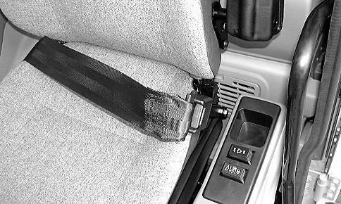
1.RIGHT BELT STRAP
2.LATCH MECHANISM
3.RELEASE BUTTON
WARNING: Before starting the engine ensure seat belts are securely fastened. The seat belt can help insure your safety if it is used and properly maintained. Never wear a seat belt loosely or with slack in the belt system. Never wear the belt in a twisted condition or pinched between the seat structural members.
WARNING: Securely fasten your seat belt. Your machine is equipped with a ROPS cab, ROPS canopy or ROPS frame for your protection. The seat belt can help insure your safety if it is used and maintained. Never wear a seat belt loosely or with slack in the belt system. Never wear the belt in a twisted condition or pinched between the seat structural members.
SPECIFIC PRECAUTIONS TO THIS MACHINE
• Keep the load or tool as low as possible while moving the machine around the job site.
• Never smoke while refuelling.
CHAPTER 2 - SAFETY, DECALS, AND HAND SIGNALS 2-8 Issued 8-04 Bur6-34551NA
CD00E032
Figure 5
1.To latch the seat belt, pull the right belt strap from the retractor.
2.Insert the metal end into the latch mechanism on the left side of the seat.
3.To unlatch the seat belt, press the red button on the left side latch mechanism.
M437
4.The seat belt will automatically retract.
M422A
1 2 3
WARNING: An illegible or missing decal can have far-reaching consequences. Inspect decals daily.
WARNING: Make sure that the decals are perfectly legible, clean them regularly and replace decals that are destroyed, lost, painted over or no longer legible, with new ones. When parts bearing decals are replaced, be sure to put new decals on each new part.
NOTE: When you clean the decals, use only a cloth, water and soap. Do not use solvents, gasoline, etc.
NOTE: This chapter only covers decals relating to safety and machine operation and servicing. For information on all decals for the machine, consult your authorized dealer.
KHP1533-00
This decal warns of the hazard associated with rotating parts and components.
KHP1537-00
6
This 3 panel decal explains the Danger of electrocution, the importance of reading and understanding the operator’s manual and that attachment interference may cause damage to the operator’s compartment.
KHP1013
This decal instructs the operator to use diesel fuel only.
BS00M141
Figure 7
This decal warns of Danger and to keep clear of swinging upperstructure to prevent serious bodily injury.
KHP1535
This decal cautions that some surfaces may cause burns.
CHAPTER 2 - SAFETY, DECALS, AND HAND SIGNALS 2-9 6-34551NAIssued 8-04 Bur
DECALS
Figure
Figure 8
Figure 9
Figure 10
Figure 11
This decal warns that improper jumper cable connections may cause the machine to move out of control causing serious injury or death.
This decal warns the operator or technican that grease may be under heavy pressure and cause serious injury or death.
This decal warns that starting in gear can cause serious injury or death and the engine should be started from the operator’s seat only.
This decal reminds the operator or technican of procedures for checking the Hydraulic fluid level.
CHAPTER 2 - SAFETY, DECALS, AND HAND SIGNALS 2-10 Issued 8-04 Bur6-34551NA
321-6718
Figure 12
321-7040
Figure 13
167327A1
Figure 14
167328A1
Figure 15
This decal shows the function of the left-hand and right-hand control levers.
This decal warns of the Danger if standing too close to a machine that becomes electrified.
This decal warns of the hazards that may be encountered when servicing the batteries and using jumper cables.
This decal warns the operator to change the function decal in the cab to match the control pattern setting.
KHP1498
This decal shows the function of the travel control levers and pedals.
Part number:
KHP1498 (standard)
KHP1484 (standard and option)
KHP1511 (standard + option + offset boom)
KHP1572 (with dozer blade)
KHP1573 (with dozer blade and option)
CHAPTER 2 - SAFETY, DECALS, AND HAND SIGNALS 2-11 6-34551NAIssued 8-04 Bur
167324A1
Figure 16
KHP1536 Figure 17
CS00F530
Figure 18
BS02G143
Figure 19
Figure 20
This decal shows the function of the backfill blade.
This decal warns to keep clear of rotating fans and belts.
KHP1542
This decal warns that hot hydraulic fluid or hydraulic fluid under pressure may cause burns or bodily injury. See Releasing Hydraulic Pressure in this manual.
This decal shows the location and way to use the emergency exit. (rear window)
This decal warns that the radiator system must be allowed to cool and pressure must be released before removing the radiator cap.
BS00M132
This decal cautions t hat contact may be made between the attachment and backfill blade during certain digging operations.
CHAPTER 2 - SAFETY, DECALS, AND HAND SIGNALS 2-12 Issued 8-04 Bur6-34551NA
KHP0859
Figure 21
Figure 22
CT02C010
Figure 23
321-3596
Figure 24
CS98N560
Figure 25
Figure 26
This decal cautions that the hood must be locked into position to avoid serious injury.
This decal cautions about stepping on exposed cylinder which could cause serious injury from falling.
This decal cautions not to walk on engine cover.
This decal cautions of a crush hazard from a swinging boom which can cause serious injury or death.
This decal cautions attachment impact hazard with cab during swinging.
CHAPTER 2 - SAFETY, DECALS, AND HAND SIGNALS 2-13 6-34551NAIssued 8-04 Bur
KHP-1010-00
Figure 27
KHP1011-00
Figure 28
BS04H100
Figure 29
BS04H101
Figure 30
BS04H102
Figure 31
CHAPTER 2 - SAFETY, DECALS, AND HAND SIGNALS
HAND SIGNALS
When operating the machine, never attempt to carry out tasks calling for fine control or to work in areas where visibility is poor or impaired without seeking the assistance of a signalman. Make perfectly sure that you and the signalman understand the signals to be used.
PDE0004A
START THE ENGINE
PDE0002
33 SHUT DOWN THE ENGINE
PDE0005A
36 GO THIS FAR
PDE0003A
COME TO ME
Wave hands back and forth (palms inwards).
Figure 34
RAISE LOAD OR TOOL
Wave hands back and forth.
37
PDE0004
ALL STOP AND HOLD
38
PDE0003
MOVE AWAY FROM ME
Wave hands back and forth (palms outwards).
Figure 35
PDE0005
EMERGENCY STOP
Wave hands back and forth.
39
2-14 Issued 8-04 Bur6-34551NA
PDE0002A
Figure 32
Figure
Figure
Figure
Figure
Figure
PDE0006A
40 RAISE LOAD OR TOOL
RAISE TOOL
PDE0006
Figure 41 LOWER LOAD OR TOOL
TURN THE MACHINE TO THE LEFT (SWING LOAD LEFT) To stop movement, stop moving hand and clench fist.
PDE0007A
Figure 42
PDE0007
SLOWLY RAISE THE LOAD OR TOOL
PDE0008
46
TURN MACHINE RIGHT (SWING LOAD RIGHT) To stop movement, stop moving hand and clench fist.
SLOWLY LOWER THE LOAD OR TOOL
43
LOWER TOOL
2 - SAFETY,
2-15 6-34551NAIssued 8-04 Bur
CHAPTER
DECALS, AND HAND SIGNALS
Figure
Figure
PDE0009A
Figure 44
PDE0008A
Figure 45
Figure
PDE0009
Figure 47
2-16 Issued 8-04 Bur6-34551NA
CHAPTER 2 - SAFETY, DECALS, AND HAND SIGNALS
PDE0010A
RAISE TOOL
Figure 48
PDE0010
LOWER
Figure 49
TOOL
PDE0011A
Figure 50
RETRACT ARM
PDE0011
Figure 51 EXTEND ARM
PDE0012A
Figure 52 FILL TOOL
PDE0012
Figure 53 EMPTY TOOL
Chapter 3
CHAPTER 3 - INSTRUMENTS
3-1 Issued 8-04 Bur6-34551NA
AND CONTROLS
INSTRUMENTS
TABLE OF CONTENTS CAB DOOR . . . . . . . . . . . . . . . . . . . . . . . . . . . . . . . . . . . . . . . . . . . . . . . . . . . . . . . . . . . . . . . . . . . . . . . . . . . . . 3-3 STEPS AND ACCESS HANDLES . . . . . . . . . . . . . . . . . . . . . . . . . . . . . . . . . . . . . . . . . . . . . . . . . . . . . . . . . . . . 3-4 POSITION OF THE OPERATOR’S COMPARTMENT CONTROLS AND ACCESSORIES . . . . . . . . . . . . . . . . 3-5 RIGHT-HAND CONTROL ARM . . . . . . . . . . . . . . . . . . . . . . . . . . . . . . . . . . . . . . . . . . . . . . . . . . . . . . . . . . . . . . 3-6 INSTRUMENT PANEL . . . . . . . . . . . . . . . . . . . . . . . . . . . . . . . . . . . . . . . . . . . . . . . . . . . . . . . . . . . . . . . . . . . . . 3-7 LEFT-HAND CONTROL ARM FOR CX75SR . . . . . . . . . . . . . . . . . . . . . . . . . . . . . . . . . . . . . . . . . . . . . . . . . . . 3-9 LEFT-HAND CONTROL ARM FOR CX135SR . . . . . . . . . . . . . . . . . . . . . . . . . . . . . . . . . . . . . . . . . . . . . . . . . 3-10 WORKING LIGHT SWITCH . . . . . . . . . . . . . . . . . . . . . . . . . . . . . . . . . . . . . . . . . . . . . . . . . . . . . . . . . . . . . . . . 3-11 WINDSHIELD WASHER SWITCH . . . . . . . . . . . . . . . . . . . . . . . . . . . . . . . . . . . . . . . . . . . . . . . . . . . . . . . . . . . 3-11 WINDSHIELD WIPER SWITCH . . . . . . . . . . . . . . . . . . . . . . . . . . . . . . . . . . . . . . . . . . . . . . . . . . . . . . . . . . . . . 3-11 HIGH SPEED TRAVEL SWITCH . . . . . . . . . . . . . . . . . . . . . . . . . . . . . . . . . . . . . . . . . . . . . . . . . . . . . . . . . . . . 3-11 HEATING, VENTILATION AND AIR-CONDITIONING CONTROL . . . . . . . . . . . . . . . . . . . . . . . . . . . . . . . . . . 3-12 FUNCTION CANCELLATION LEVER . . . . . . . . . . . . . . . . . . . . . . . . . . . . . . . . . . . . . . . . . . . . . . . . . . . . . . . . 3-13 ARM AND UPPERSTRUCTURE SWING LEFT-HAND CONTROL LEVER . . . . . . . . . . . . . . . . . . . . . . . . . . . 3-13 BOOM AND BUCKET RIGHT-HAND CONTROL LEVER . . . . . . . . . . . . . . . . . . . . . . . . . . . . . . . . . . . . . . . . . 3-14 TRAVEL CONTROL . . . . . . . . . . . . . . . . . . . . . . . . . . . . . . . . . . . . . . . . . . . . . . . . . . . . . . . . . . . . . . . . . . . . . . 3-15 OFFSET BOOM CONTROL PEDAL (IF EQUIPPED) . . . . . . . . . . . . . . . . . . . . . . . . . . . . . . . . . . . . . . . . . . . . 3-16 OPTION PEDAL . . . . . . . . . . . . . . . . . . . . . . . . . . . . . . . . . . . . . . . . . . . . . . . . . . . . . . . . . . . . . . . . . . . . . . . . . 3-16 UNLOCKING AND LOCKING OF PEDALS . . . . . . . . . . . . . . . . . . . . . . . . . . . . . . . . . . . . . . . . . . . . . . . . . . . . 3-16 Unlocking . . . . . . . . . . . . . . . . . . . . . . . . . . . . . . . . . . . . . . . . . . . . . . . . . . . . . . . . . . . . . . . . . . . . . . . . . . . . 3-16 Locking . . . . . . . . . . . . . . . . . . . . . . . . . . . . . . . . . . . . . . . . . . . . . . . . . . . . . . . . . . . . . . . . . . . . . . . . . . . . . . 3-16 DOZER BLADE CONTROL LEVER (IF EQUIPPED) . . . . . . . . . . . . . . . . . . . . . . . . . . . . . . . . . . . . . . . . . . . . . 3-17 CAB LIGHT . . . . . . . . . . . . . . . . . . . . . . . . . . . . . . . . . . . . . . . . . . . . . . . . . . . . . . . . . . . . . . . . . . . . . . . . . . . . . 3-17 COAT HANGER HOOK . . . . . . . . . . . . . . . . . . . . . . . . . . . . . . . . . . . . . . . . . . . . . . . . . . . . . . . . . . . . . . . . . . . 3-17 REAR RIGHT-HAND SIDE WINDOW . . . . . . . . . . . . . . . . . . . . . . . . . . . . . . . . . . . . . . . . . . . . . . . . . . . . . . . . 3-17 STORAGE COMPARTMENT . . . . . . . . . . . . . . . . . . . . . . . . . . . . . . . . . . . . . . . . . . . . . . . . . . . . . . . . . . . . . . . 3-18 STORAGE TRAY . . . . . . . . . . . . . . . . . . . . . . . . . . . . . . . . . . . . . . . . . . . . . . . . . . . . . . . . . . . . . . . . . . . . . . . . 3-18 ASHTRAY . . . . . . . . . . . . . . . . . . . . . . . . . . . . . . . . . . . . . . . . . . . . . . . . . . . . . . . . . . . . . . . . . . . . . . . . . . . . . . 3-18 CAB RADIO COMPARTMENT . . . . . . . . . . . . . . . . . . . . . . . . . . . . . . . . . . . . . . . . . . . . . . . . . . . . . . . . . . . . . . 3-18 SPEAKER COMPARTMENTS . . . . . . . . . . . . . . . . . . . . . . . . . . . . . . . . . . . . . . . . . . . . . . . . . . . . . . . . . . . . . . 3-18 FUSE BOX . . . . . . . . . . . . . . . . . . . . . . . . . . . . . . . . . . . . . . . . . . . . . . . . . . . . . . . . . . . . . . . . . . . . . . . . . . . . . 3-18 OPERATOR'S SEAT . . . . . . . . . . . . . . . . . . . . . . . . . . . . . . . . . . . . . . . . . . . . . . . . . . . . . . . . . . . . . . . . . . . . . 3-19 WINDSHIELD . . . . . . . . . . . . . . . . . . . . . . . . . . . . . . . . . . . . . . . . . . . . . . . . . . . . . . . . . . . . . . . . . . . . . . . . . . . 3-22 Opening . . . . . . . . . . . . . . . . . . . . . . . . . . . . . . . . . . . . . . . . . . . . . . . . . . . . . . . . . . . . . . . . . . . . . . . . . . . . . 3-22 Closing . . . . . . . . . . . . . . . . . . . . . . . . . . . . . . . . . . . . . . . . . . . . . . . . . . . . . . . . . . . . . . . . . . . . . . . . . . . . . . 3-22 LOWER FRONT WINDOW . . . . . . . . . . . . . . . . . . . . . . . . . . . . . . . . . . . . . . . . . . . . . . . . . . . . . . . . . . . . . . . . 3-23 WINDOW-BREAKER HAMMER . . . . . . . . . . . . . . . . . . . . . . . . . . . . . . . . . . . . . . . . . . . . . . . . . . . . . . . . . . . . 3-23 AIR VENTS . . . . . . . . . . . . . . . . . . . . . . . . . . . . . . . . . . . . . . . . . . . . . . . . . . . . . . . . . . . . . . . . . . . . . . . . . . . . . 3-23 REAR VIEW MIRRORS - CX75SR, CX80 . . . . . . . . . . . . . . . . . . . . . . . . . . . . . . . . . . . . . . . . . . . . . . . . . . . . . 3-24 On the cab . . . . . . . . . . . . . . . . . . . . . . . . . . . . . . . . . . . . . . . . . . . . . . . . . . . . . . . . . . . . . . . . . . . . . . . . . . . 3-24
AND CONTROLS
3-2 Issued 8-04 Bur6-34551NA On the upperstructure . . . . . . . . . . . . . . . . . . . . . . . . . . . . . . . . . . . . . . . . . . . . . . . . . . . . . . . . . . . . . . . . . . .3-24 Rear . . . . . . . . . . . . . . . . . . . . . . . . . . . . . . . . . . . . . . . . . . . . . . . . . . . . . . . . . . . . . . . . . . . . . . . . . . . . . . . .3-24 REAR VIEW MIRRORS CX135SR . . . . . . . . . . . . . . . . . . . . . . . . . . . . . . . . . . . . . . . . . . . . . . . . . . . . . . . . . . 3-24 On the cab . . . . . . . . . . . . . . . . . . . . . . . . . . . . . . . . . . . . . . . . . . . . . . . . . . . . . . . . . . . . . . . . . . . . . . . . . . . .3-24 On the upperstructure . . . . . . . . . . . . . . . . . . . . . . . . . . . . . . . . . . . . . . . . . . . . . . . . . . . . . . . . . . . . . . . . . . .3-25 Rear . . . . . . . . . . . . . . . . . . . . . . . . . . . . . . . . . . . . . . . . . . . . . . . . . . . . . . . . . . . . . . . . . . . . . . . . . . . . . . . .3-25 FUEL TANK . . . . . . . . . . . . . . . . . . . . . . . . . . . . . . . . . . . . . . . . . . . . . . . . . . . . . . . . . . . . . . . . . . . . . . . . . . . . 3-25 UPPER HOOD - CX75SR, CX80 . . . . . . . . . . . . . . . . . . . . . . . . . . . . . . . . . . . . . . . . . . . . . . . . . . . . . . . . . . . 3-25 ENGINE HOOD . . . . . . . . . . . . . . . . . . . . . . . . . . . . . . . . . . . . . . . . . . . . . . . . . . . . . . . . . . . . . . . . . . . . . . . . . 3-26 CX75SR, CX80 . . . . . . . . . . . . . . . . . . . . . . . . . . . . . . . . . . . . . . . . . . . . . . . . . . . . . . . . . . . . . . . . . . . . . . . .3-26 CX135SR . . . . . . . . . . . . . . . . . . . . . . . . . . . . . . . . . . . . . . . . . . . . . . . . . . . . . . . . . . . . . . . . . . . . . . . . . . . .3-26 SIDE DOORS . . . . . . . . . . . . . . . . . . . . . . . . . . . . . . . . . . . . . . . . . . . . . . . . . . . . . . . . . . . . . . . . . . . . . . . . . . 3-27 Left-hand rear side door . . . . . . . . . . . . . . . . . . . . . . . . . . . . . . . . . . . . . . . . . . . . . . . . . . . . . . . . . . . . . . . . .3-27 Right-hand rear side door . . . . . . . . . . . . . . . . . . . . . . . . . . . . . . . . . . . . . . . . . . . . . . . . . . . . . . . . . . . . . . . .3-27 Right-hand front side door . . . . . . . . . . . . . . . . . . . . . . . . . . . . . . . . . . . . . . . . . . . . . . . . . . . . . . . . . . . . . . . .3-27 ROTATING BEACON CABLE (OPTION) . . . . . . . . . . . . . . . . . . . . . . . . . . . . . . . . . . . . . . . . . . . . . . . . . . . . . 3-28 TOWING POINT . . . . . . . . . . . . . . . . . . . . . . . . . . . . . . . . . . . . . . . . . . . . . . . . . . . . . . . . . . . . . . . . . . . . . . . . 3-28 LOAD HANDLING EYES . . . . . . . . . . . . . . . . . . . . . . . . . . . . . . . . . . . . . . . . . . . . . . . . . . . . . . . . . . . . . . . . . . 3-29 WINDSHIELD WASHER RESERVOIR . . . . . . . . . . . . . . . . . . . . . . . . . . . . . . . . . . . . . . . . . . . . . . . . . . . . . . . 3-29 TOOL SUPPLY VALVES (OPTIONAL) . . . . . . . . . . . . . . . . . . . . . . . . . . . . . . . . . . . . . . . . . . . . . . . . . . . . . . . 3-29 TOOL FLOW SELECTOR VALVE (OPTIONAL) . . . . . . . . . . . . . . . . . . . . . . . . . . . . . . . . . . . . . . . . . . . . . . . . 3-30
CHAPTER 3 - INSTRUMENTS AND CONTROLS
WARNING: When seated in the operator’s compartment, with the engine running, make sure that you do not to operate the left-hand control lever inadvertently when unlocking the door. To prevent an incident, place the left-hand control arm in the raised position. See Function cancellation lever.
WARNING: Be careful not to get your hand or anything caught in the door when closing it.
WARNING: Do not leave the door ajar. Fix it in a latched position.
To open the door, use the handle (1) from the outside and use the handle (2) from the inside.
The door can be latched in completely open position. To unlatch the door, push the lever (3) downward.
3 - INSTRUMENTS
3-3 6-34551NAIssued 8-04 Bur
CHAPTER
AND CONTROLS
CAB DOOR
CT02C030
Figure 1
CT02C031
Figure 2
CT02C032
Figure 3
1 2 3
STEPS AND ACCESS HANDLES
WARNING: Always maintain three point support while getting on and off the machine and entering or exiting the operator’s cab. A three point support system has been provided that enables a person to use simultaneously two hands and one foot or two feet and one hand while ascending, descending or moving about the machine.
WARNING: To get in or out of the cab, it is imperative that the upperstructure frame is in line with the undercarriage.
WARNING: Clean the steps and access handles and remove all traces of grease, oil, mud, and (in winter) ice.
WARNING: Never jump down from the machine. When leaving the machine or upperstructure, always face the machine and use the steps and access handles.
When getting down from or getting onto the machine, use the steps, the tracks and the access handles.
CHAPTER 3 - INSTRUMENTS
3-4 Issued 8-04 Bur6-34551NA
AND CONTROLS
CT02C051
Figure 4
CX75SR, CX80
CT02C033
Figure 5 CX135SR
CT02C034
Figure 6
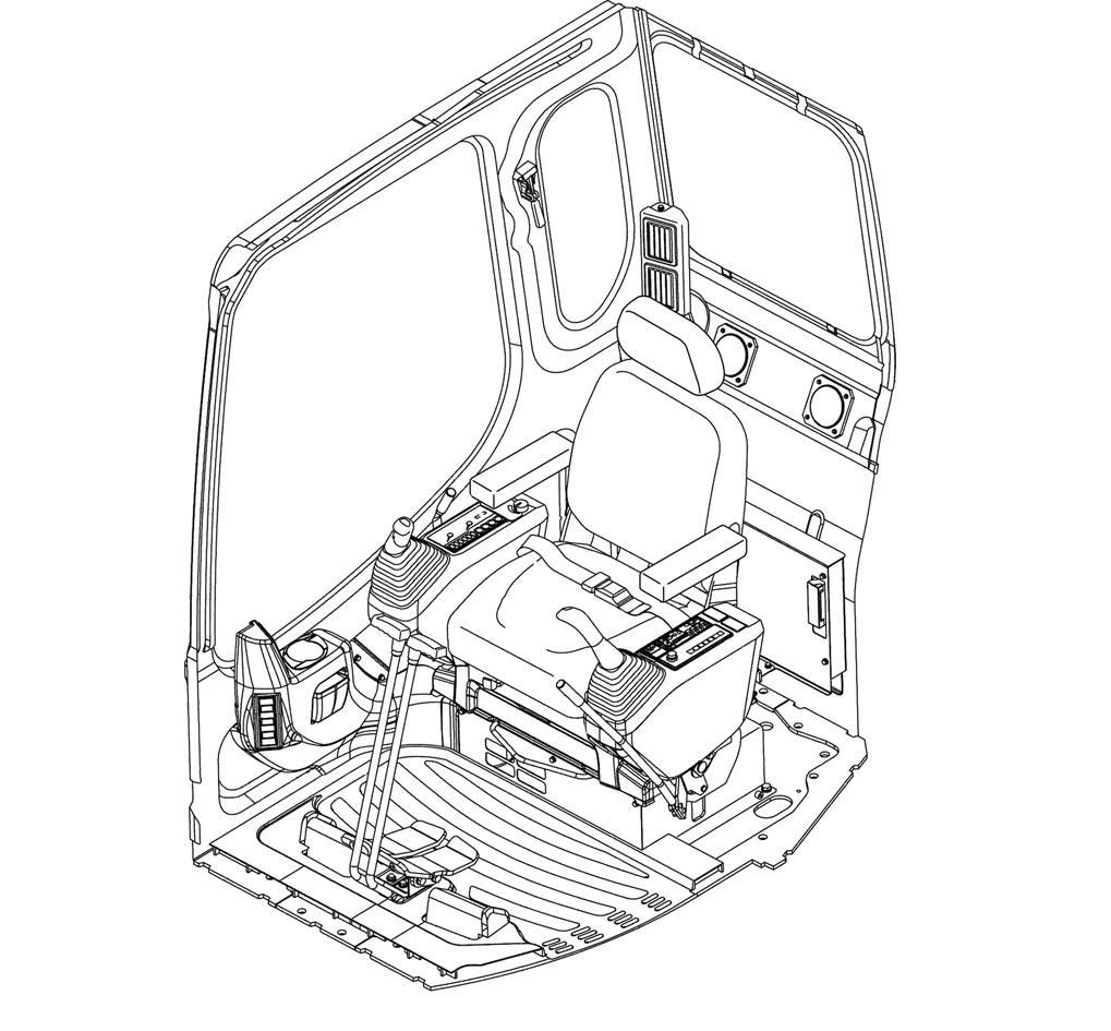
POSITION OF THE OPERATOR’S COMPARTMENT CONTROLS AND ACCESSORIES
WARNING: Before starting the engine, make sure that you are fully aware of the location of and the function of each control. Incorrect operation of the controls can cause serious injuries.
CHAPTER 3 - INSTRUMENTS
3-5 6-34551NAIssued 8-04 Bur
AND CONTROLS
CT02C282
Figure 7
1.OPERATOR'S SEAT9.INSTRUMENT PANEL
2.FUNCTION CANCELLATION LEVER10.HEATING, AIR-CONDITIONING, AND OPTIONAL CONTROL
3.LEFT-HAND CONTROL LEVER
11.RIGHT-HAND CONTROL LEVER
4.FOOT REST (PEDAL LOCKED)12.AIR VENTS
5.LEFT-HAND TRAVEL CONTROL PEDAL AND LEVER13.RIGHT-HAND CONTROL ARM
6.RIGHT-HAND TRAVEL CONTROL PEDAL AND LEVER14.LEFT-HAND CONTROL ARM
7.DOZER BLADE LEVER (IF EQUIPPED)15.OFFSET PIVOT CONTROL PEDAL (CX80)
1 8 8 2 3 4 4 5 6 9 11 12 12 14 13 12 10 7 15
8.OPTION PEDALS
1.INSTRUMENT PANEL
For more details, see Instrument panel.
2.STARTER SWITCH
(CX136SR)
This switch has four positions, ON (contact), START (engine ignition), OFF (engine shut-down) and ACC (accessory current supply). See Starting the engine in the Operating Instructions section.
This key is also used to lock the cab door, the engine hood, the side doors, and the fuel tank cap.
(CX75SR, CX80)
This switch has five positions, “ON” (contact), “START” (engine ignition), “OFF” (engine shut-down), “ACC” (accessory current supply), and “HEAT” (preheating). See Starting the engine in the Operating Instructions section. This key is also used to lock the cab door, the engine hood, the side doors, and the fuel tank cap.
3.ENGINE THROTTLE BUTTON
This button enables the increase or reduction in the engine speed. For LOW IDLE position, turn the button to the left. For MAXIMUM SPEED, turn the button to the right.
If there is no change in engine speed, press and release the engine automatic idle speed selector (See item 4).
4.ENGINE IDLE SPEED SELECTOR
This control enables automatic engine idle without operating the throttle button. For engine automatic idle, press and release the control and the engine will be in LOW IDLE position. Press once again on the control then release it, the engine returns to its initial speed.
5.DOZER BLADE CONTROL LEVER (If equipped) This lever enables the operation of the dozer blade, see Dozer blade control lever.
CHAPTER 3 - INSTRUMENTS AND CONTROLS 3-6 Issued 8-04 Bur6-34551NA
RIGHT-HAND CONTROL ARM
CT02C046 Figure 8
2 4 3 1 5
WARNING: The role of the instrument panel is to indicate the state of the machine and quickly warn the operator in case of any malfunction, through alarms. It should not be used for checking or maintenance. The instrument panel is not waterproof. Make sure that it does not get wet
1.FUEL LEVEL INDICATOR
When the indicator needle moves closer to the E zone, fuel needs to be added in the reservoir. The indicator functions when the key switch is in the ON position.
2.ENGINE COOLANT TEMPERATURE INDICATOR
This indicator is divided into two zones: white zone, normal operating temperature and red zone: hot. The indicator functions when the key switch is in the ON position.
IMPORTANT: If the needle is in the red zone, move the machine to a safe location, lower the attachment to the ground, shut down the engine, remove the ignition key and check the cooling system to determine the source of the malfunction.
3.HOURMETER
The hourmeter enables service operations to be scheduled. Its indications are similar to those of a watch when the engine is running. Its operation is indicated by the blinking of a green indicator lamp. See section Servicing intervals.
4.OVERHEATING INDICATOR LAMP
The audible warning device will sound
This indicator lamp shows that the engine coolant or hydraulic fluid temperature is abnormally high. Bring the engine to idle mode and reduce the water or fluid temperature. Check and clean the radiator.
5.ENGINE
OIL PRESSURE INDICATOR LAMP
The audible warning device will sound
This indicator lamps up when the engine oil pressure is too low. If the indicator lamps up during operation, move the machine to a safe location, lower the attachment to the ground, shut down the engine, remove the ignition key and determine the source of the malfunction.
CHAPTER 3 - INSTRUMENTS AND CONTROLS 3-7 6-34551NAIssued 8-04 Bur INSTRUMENT PANEL
CT02C046
Figure 9
135_TBD7
Figure 10
135_TBD8
2 3 1 4 5
Figure 11
135_TBD9
6.FUEL LEVEL INDICATOR LAMP
The audible warning device will sound
This indicator lamps up when the fuel level in the reservoir is too low, fuel must be added as soon as possible.
IMPORTANT: Do not wait until the fuel tank is completely empty before refilling or it will be necessary to bleed the fuel circuit.
7.BATTERY CHARGE INDICATOR LAMP
The audible warning device will sound
This indicator lamps up when the alternator/fan belt is broken or when the alternator is not charging the battery any more. If the indicator lamps up during operation, move the machine to a safe location, lower the attachment to the ground, shut down the engine, remove the ignition key and determine the source of the malfunction.
9 10 11 7 8 12 13
9.PREHEATING INDICATOR LAMP
The audible warning device will sound
This indicator lamps up when the key switch is in the ON position and the temperature is low. Wait for the indicator lamp to go off before starting the engine.
135_TBD12
10.Windshield wiper switch
See Windshield wiper switch for its use.
11.Windshield washer switch
See Windshield washer switch for its use.
12.Working light switch
See Working light switch for its use.
13.High speed travel switch.
See High speed travel switch for its use.
135_TBD10
8.ENGINE ELECTRIC CIRCUIT INDICATOR LAMP CX135SR
The audible warning device will sound
This indicator lamps up in case of failure of the engine electric circuit (short-circuit or disconnection). Check the electric circuits of the engine.
135_TBD11

CHAPTER 3 - INSTRUMENTS AND CONTROLS 3-8 Issued 8-04 Bur6-34551NA
CT02C046
Figure 12
Figure 13
Figure 14
Figure 15
Figure 16
6
1.HORN
To sound the horn, press at the end of the Left-hand control lever.
IMPORTANT: Always sound the horn before operating the machine.
2.FUNCTION CANCELLATION LEVER
The shape of the function cancellation lever was designed to prevent the operator from leaving the operator’s compartment without having raised the lever beforehand. See function cancellation lever.
WARNING: To access or exit the operator’s compartment, the function cancellation lever must be in the raised position. Never try to avoid this basic requirement.
3.OPTION CONTROL (Optional)
This two-position switch enables the activation of options such as the hydraulic breaker, grab, shears, etc. Place the switch in one of the two positions depending on the accessories to be used. See Auxiliary hydraulic systems in the Operating Instructions section.
4.HEATING AND VENTILATION CONTROL
See Heating and ventilation control for its use.
5.HEATING, VENTILATION OR AIR-CONDITIONING CONTROL (Optional)
See Heating, ventilation or air-conditioning control for its use.
CHAPTER 3 - INSTRUMENTS AND CONTROLS 3-9 6-34551NAIssued 8-04 Bur
LEFT-HAND CONTROL ARM FOR CX75SR, CX80 CT02C064 Figure 17
2 1 3
4 5
1.HORN
To sound the horn, press at the end of the left-hand control lever.
IMPORTANT: Always sound the horn before operating the machine.
2.FUNCTION CANCELLATION LEVER
The shape of the function cancellation lever was designed to prevent the operator from leaving the operator’s compartment without having raised the lever beforehand. See function cancellation lever.
WARNING: To access or exit the operator’s compartment, the function cancellation lever must be in the raised position. Never try to avoid this basic requirement.
3.OPTION CONTROL (Optional)
This two-position switch enables the activation of options such as the hydraulic breaker, grab, shears, etc. Place the switch in one of the two positions depending on the accessories to be used. See Auxiliary hydraulic systems in the Operating Instructions section.
4.EMERGENCY SHUT DOWN SWITCH
This switch shuts down of the engine in case of an emergency. See Shutting down the engine in the Operating Instructions section.
IMPORTANT: This switch should only be used in case of an emergency. Do not use it on a day-to-day basis.
5.HEATING AND VENTILATION CONTROL
See Heating and ventilation control for its use.
6.HEATING, VENTILATION OR AIR-CONDITIONING CONTROL (Optional)
See Heating, ventilation or air-conditioning control for its use.
CHAPTER 3 - INSTRUMENTS AND CONTROLS 3-10 Issued 8-04 Bur6-34551NA LEFT-HAND CONTROL ARM FOR CX135SR
CT02C047 Figure 18
2 1 3 4
5 6
WORKING LIGHT SWITCH
WINDSHIELD WIPER SWITCH
CT02C053
Figure 19
This switch switches the working lights on or off. Press the button, the instrument panel as well as the working lights comes on. Press the button again to switch them off.
WINDSHIELD WASHER SWITCH
CT02C055
Figure 21
This switch has three positions: Shut down, Intermittent and Continuous. Press the switch for intermittent operation of the windshield wiper, the lamp (I) comes on. Press the switch again to obtain continuous operation of the windshield wiper, the lamp (II) comes on. Press the switch once more for the function to cease.
Do not operate the windshield wiper if the windshield is dry, as this may damage the windshield wiper.
HIGH SPEED TRAVEL SWITCH
CT02C054
Figure 20
Press and hold the switch for the windshield washer and the windshield wiper to function, release the switch to stop this operation.
Never operate the windshield washer when the reservoir is empty, as this may damage the electric pump.
CT02C056
Figure 22
When the switch is pressed, the travel speed goes from low to high. A red indicator lamps up when the travel is in high speed mode.
When the engine is started, low speed is automatically selected.
WARNING: If the travel speed is changed during travel, the machine may veer off course. Shut down the machine before changing speeds.
Low speed: Suited for travel on a slope or on difficult terrain.
High speed: Suited for travel on level ground. As soon as the travel load becomes too great, the machine automatically returns to low speed.
CHAPTER 3 - INSTRUMENTS AND CONTROLS 3-11 6-34551NAIssued 8-04 Bur