Engine
INTRODUCTION
[10.001] Engine and crankcase
[10.102] Pan and covers
[10.106] V alve drive and gears
[10.101] Cylinder heads
[10.105] Connecting rods and pistons
Crankshaft and flywheel
[10.218] Fuel injection system
[10.202] Air cleaners and lines
[10.250] T urbocharger and lines
[10.254] Intake and exhaust manifolds and muf fler
[10.400] Engine cooling system
[10.304] Engine lubrication system .
Hydraulic systems
Hydraulic systems
Reservoir , cooler , and filters
V ariable displacement pump
Main control valve
Hydraulic hand control
Hydraulic foot control
Hydraulic swing system
Hydraulic travel system
Hydraulic central joint
Boom hydraulic system
Excavator and backhoe bucket hydraulic system
Swing arm hydraulic system
Dozer blade cylinders
Frames and ballasting
Upper frame
Swing ring assembly
Ballasts and supports
Tracks and track suspension
T rack frame and driving wheels
T racks
T rack tension units
T rack rollers
Electrical systems
Electrical system
Harnesses and connectors
Engine control system
Engine starting system
Alternator
Battery
Fuel tank system
Engine oil system
External lighting
Cab platform harnesses and connectors
dippers, and buckets
14] Boom pivoting support
Boom
Dipper arm
Bucket
Dozer blade and arm
10] Dozer blade
Cab
10] Operator platform less cab
14] Operator protections Machine shields and guards
16] Fenders and guards

Foreword - Important notice regarding equipment servicing
All repair and maintenance work listed this manual must carried out only qualified dealership strictly complying with the instructions and whenever the special
Anyone who performs repair and maintenance operations without complying with the procedures provided herein shall responsible for any subsequent
The manufacturer and all the organizations its distribution chain, including - without limitationnational, regional, local reject any responsibility for damages caused parts and / components not approved the facturer , including those used for the servicing repair the product manufactured marketed the manufacturer any case, warranty given attributed the product manufactured marketed the manufacturer case damages caused parts and / components not approved the manufacturer
The information this manual - - date the date the the policy the manufacturer for continuous Some information could not updated due modifications a technical commercial type, changes the laws and regulations dif ferent countries.
case refer your CASE
CONSTRUCTION Sales and Service
Safety rules

Personal safety
This the safety alert used alert you potential personal injury Obey all safety messages that follow this symbol avoid possible death injury
Throughout this manual you will find the signal words W and CAUTION followed special These precautions are intended for the personal safety you and those working with
Read and understand all the safety messages this manual before you operate service the
DANGER indicates a hazardous situation not will result death serious injury
W ARNING indicates a hazardous situation not could result death serious injury
CAUTION indicates a hazardous situation not could result minor moderate injury
F AILURE T O FOLLOW
Machine safety
NOTICE: Notice indicates a situation that, not avoided, could result machine property damage.
Throughout this manual you will find the signal word Notice followed special instructions prevent machine property damage. The word Notice used address practices not related personal safety .
Information
NOTE: Note indicates additional information that clarifies other information this
Throughout this manual you will find the word Note followed additional information about a step, other information the The word Note not intended address personal safety property
Personal safety
NOTICE: The proper and safe lubrication and maintenance for this recommended Manufacturer , are outlined the OPERA T OR’S MANUAL for the Improper performance lubrication maintenance procedures are dangerous and could result injury Read and understand the MANUAL before performing any lubrication
The serviceman mechanic may unfamiliar with many the systems this machine. This makes a careful use the systems very important when performing maintenance Sound knowledge the system and components important before the removal disassembly any
Because the size some the machine the serviceman mechanic should check the weights noted this Use proper lifting procedures when removing any W eight components table shown this
The following a list basic precautions that must always
Read and understand all W arning plates and decals the machine before Maintaining Repairing this
Always wear protective glasses and protective shoes when working around particular , wear tive glasses when using punches drifts any part the machine Use welders gloves, hood / goggles, apron and the protective clothing appropriate the welding job being performed. not wear loose fitting torn Remove all rings from loose jewellery , confine long hair and loose ing before working this machinery
Disconnect the battery and hang a tag the operator ’ s Remove starter key make all repairs with the machine parked a level and firm Block the machine does not roll while working under the machine. Hang a tag the operator ’ s seat. not work any machine that supported only jacks a Always use blocks stops for the jack before carrying out any disassembly operation.
NOTICE: not operate this machine unless you have read and understood all instructions contained this manual. Improper machine operation dangerous and could result injury
Relieve all pressure air , oil water systems before any lines, fittings related items are disconnected Always make sure all raised components are blocked correctly and alert for possible pressure when disconnecting any device from a system under
Lower the dozer other attachments the ground before performing any work the this cannot make sure the blade other attachment blocked correctly prevent from dropping unexpectedly .
Use steps and grab handles when mounting dismounting a Remove any debris mud from walkways work platforms before using Always face the machine when using ladders and When not possible use the designed access provide scaf platforms perform safe repair
T o avoid back injury , use a hoist when lifting components which weigh lb) Make sure all are good condition and are the correct capacity sure hooks are positioned correctly Lifting eyes are not side loaded during a lifting
T o avoid alert for hot parts and surfaces immediately after stopping the machine such hot fluids tubes and compartment
1 careful when removing cover Gradually back f the last two capscrews nuts located opposite ends the cover device and carefully pry the cover loose relieve any spring other before removing the last two capscrews nuts completely .
Be careful when removing filler breathers and plugs the Hold a rag over the cap plug prevent being sprayed splashed liquids under Danger even greater the machine has just been liquids might boiling
Always use the proper tools that are good condition and that are suited for the job sure you understand how use them before performing any service
Reinstall all clamps with the same spare part number not use clamps inferior quality replacement necessary .
Repairs which require welding should performed only with the benefit the appropriate reference tion and personnel adequately trained and skilled welding Determine the type metal being welded and select the correct welding procedure and rods wires provide a metal weld strength least equivalent that the parent Make sure disconnect the battery before any welding operation performed.
not damage wiring during removal
Reinstall the wiring not damaged nor will damaged operation the machine contacting sharp rubbing against some object hot not connect wiring a line containing sure all protective including guards and are properly installed and functioning correctly before starting a repair . a guard shield must removed perform the repair work, use extra caution and replace the guard shield after repair
18. Performing maintenance and repair operations while the bucket lifted dangerous, because there the sibility a device not fail lower such device and place the bucket the ground before starting the
Loose dirty lubrication and hydraulic pipes and hoses may cause not bend strike high - pressure not install bent damaged Inspect tubes and hoses carefully not check for leaks with your hands. V ery small (pinhole) leaks can result a high velocity oil jet that will invisible close the
This oil can penetrate the skin and cause personal injury Use card - board paper locate pinhole T ighten connections the correct Make sure that all protections against the clamps and the ator ’ s protective devices are correctly installed order prevent excessive vibrations rubbing against other parts during operation. Shields that protect against oil spray onto hot exhaust components event a tube seal failure must installed correctly
not operate a machine any rotating part damaged contacts any other part during Any high speed rotating component that has been damaged altered should checked for balance before careful when servicing separating the Chips can fly when removing installing a track W ear safety glasses and long sleeve protective T racks can unroll very quickly when Keep away from front and rear The machine can move unexpectedly when both tracks (crawlers) are disengaged from the Block the machine prevent from
Part identification

Radiator
SER VICE MANUAL
Engine - External view
Filler port (engine oil)
T urbocharger
Air intake port (from air cleaner , optional)
Lifting eye
Coolant pump
Fan
V - belt
Crankshaft V - pulley
Filler port (engine oil)
Drain plug (engine oil)
1 Engine oil cooler (4TNV98T , 4TNV106 and 4TNV106T)
Engine oil filter
Dipstick (engine oil)
Fuel injection pump Governor lever
Fuel filter
17. Fuel cock
Fuel filter mounting
19. Lifting eye
Engine name plate
21. Rocker arm cover
Flywheel
23. Starter motor
Exhaust manifold
Generator
NOTE: This illustration shows the 4TNV98T engine (with
The drain plug (engine oil) location depends the engine installed the machine unit the fuel injection pump side (above illustration) starter motor

Engine - Static description
Emission reduction
New fuel injection pressure
• Mono plunger
• Higher injection pressure
• Injection speed timer , load timer , cold start timer control
Noise reduction
Higher stif fness cylinder block
Higher stif fness gear - case
Emission reduction
Injection nozzle
• Low suck volume
• Multi injection holes
Emission reduction
Cylinder head
• Optimal nozzle angle
• Optimal swirl ratio
• Optional valve timing
Emission reduction
Piston
• New combustion chamber
Noise reduction
New lube oil pan
• Change rotor shape for low pulsation
• Driven crankshaft directly
Emission reduction
Cylinder head
• 4 valve / cylinder (intake - exhaust -

1
• Optimal installation the injection nozzle vertical installation and location the centre cylinder
• Optimal valve timing
Emission reduction
New fuel injection nozzle
• Low suck volume
• Multi injection holes
Emission reduction
New fuel injection pump
• Mono plunger
• Higher injection pressure
• Mechanical control injection timing, speed timer , load timer , cold start timer
Emission reduction
Piston
• New combustion chamber
Noise reduction (only applied for 4TNV84T)
New lube oil pan
• Change rotor shape for low pulsation
• Driven crankshaft directly
Engine - Service instruction
Periodic maintenance schedule
The engine periodic inspection timing hard determine varies with the load qualities the fuel and lubricating oils used and handling General rules are described here.
: User - maintenance
: Parts replacement
: Shop - inspection
Whole V isual check around the machine
Fuel tank level check and fuel supply
Fuel tank drain W ater separator (Option) draining
Fuel system
Fuel system bleeding W ater separator cleaning
Fuel filter element replacement
Lube oil level check and replenishment
Lube oil replacement Lubricating oil system Lube oil filter replacement
Coolant level check and replenishment Radiator fin cleaning V - belt tension check
Coolant change Coolant pump
Coolant / water path flushing and maintenance
Rubber hose
Fuel pipe and coolant pipe inspection and maintenance
Injection governor Inspection and adjustment governor lever and accelerator
and after
time and after
Air intake system
Air cleaner cleaning and element replacement
Diaphragm assy inspection years)
T urbocharger blower
W arning lamp and instruments function check
Electrical system Battery electrolyte
level check and battery recharging
Cylinder head
Intake / exhaust valve head clearance adjustment
Intake / exhaust valve seat lapping
Fuel injection nozzle pressure inspection
Fuel injection pump and nozzle
Fuel injection timing adjustment
Fuel injection pump inspection and adjustment
*EP A allows servicing the emission related parts every 1500 - 3000 h

Engine - Inspect - Daily Inspection
sure check the following points before starting engine every day:
No.
V isual check around the machine
Fuel tank level check and fuel supply
Lube oil level check and replenishment
Coolant level check and replenishment
Fuel pipe and coolant pipe inspection and maintenance Inspection and adjustment governor lever and accelerator
W arning lamp and instruments function check
W ater separator draining
Visual check around the machine
any problem not use before the engine pairs have been
• Oil leak from the lubrication system
• Fuel leak from the fuel system
• Coolant leak from the water cooling system
• Damaged parts
• Loosened lost screws
• radiator rubber cracked V - loosened clamp
Fuel tank level check and fuel supply
Check the remaining fuel oil level the fuel tank and refuel the recommended fuel necessary
Lube oil level check and replenishment
(a) Checking oil level
Check the lubricating oil level with the dipstick (A) , after adjusting the position the machine that the engine Insert the dipstick fully and check the oil The oil shall not contaminated heavily and have priate viscosity
coolant water diesel fuel shall When lube oil supplied after the engine has been check the lube oil level after about min after the engine shutdown that the lube oil has filled the oil

The level shall between the upper (AU) and lower (AL) limit lines the dipstick (A)
4TNV106(T) (CL class)
4TNV106(T) (VM class)
Lube oil capacity may dif fer from the above volume pending engine installed a machine
(b) Replenishing oil pan with lube oil
the remaining engine oil level low , remove the filler port cap (B) and fill the oil pan with the specified engine oil the specified level through the filler port (C)
NOTE: The oil should not overfilled exceed the per limit Otherwise a naturally - aspirated engine may intake lube oil the combustion chamber during the operthen white oil hummer urgent rotation may occur , because the blow - gas reduced the suction air flow case turbocharged engine oil may jet out from the breather the engine may become faulty
Coolant check
Daily inspection coolant water should done only coolant recovery
NOTICE: Never open the radiator filler cap (R) while the engine and radiator are still Steam and hot water will spurt out and seriously burn W ait until the radiator cooled down after the engine has stopped, wrap the filler cap with a rag piece and turn the cap slowly gently lease the pressure inside the radiator
Securely tighten the filler port plug (R) after checking the diator Steam can spurt out during engine tightening loose.
(a) Checking coolant water volume
Check the coolant level the expansion tank (C) the water level close the LOW mark, open the coolant expansion tank plug (H) and replenish the tank with soft clean water the FULL
The level shall between the upper and lower limit lines the
(b) Replenishing radiator with water the coolant recovery tank water level lower than the LOW open the radiator cap (R) and check the coolant water level the radiator
Replenish the radiator with the level low
• Check the coolant level while the engine Checking when the engine hot And the water volume expanded due the
• Daily coolant level check and replenishing shall done only from the expansion Usually not open the radiator cap check
T T ighten
Loosen

NOTICE: the coolant water runs short quickly when the radiator runs short water with the coolant expansion tank level water may leaking the air tightness may lost. Increase the coolant expansion tank ter level during operation not The increased water the coolant expansion tank returns the radiator when the engine cooled the water level normal the coolant expansion tank but low the radiator , check loosened clamping the rubber hose between the radiator and coolant recovery tank tear the
Engine: The radiator shall filled

NOTE: If there is no response to click on the link above, please download the PDF document first and then clickonit.
Engine coolant water capacity may dif fer from the above volume depending engine installed a machine
Fuel pipe and coolant pipe inspection and maintenance
Check the rubber hoses for fuel and coolant water pipes the cracked hose replace with new
Check the loosened tighten
Inspection and adjustment governor lever and accelerator
Make sure the accelerator the machine unit can ated smoothly before starting the feels heavy lubricate the accelerator cable joints and ots. Adjust the accelerator cable there a dislocation excessive play between the accelerator and the governor lever Refer Engine - Inspect – Every 250 hours 3 months
W arning lamp and instruments function check
Before and after starting the check see that the alarm function normally Failure alarm cannot warn the lack the engine oil the coolant water Make a rule check the alarm operation before and after starting gine every day . Refer each manual for machine units
W ater separator draining
Drain f the water separator (W) whenever there a lot drain collected the water separator the bottom the cup (C) even the time for periodic inspection has not elapsed The cup the water separator (C) made semi - transparent material and, the cup itself, the red colored floating ring (FR) which rises the surface the drain installed visualize the amount A level sensor connected a warning device the gauge cluster provided optional
Drain f the water separator the following manner:
Prepare a waste oil container collecting waste oil. Close the fuel cock (FC)
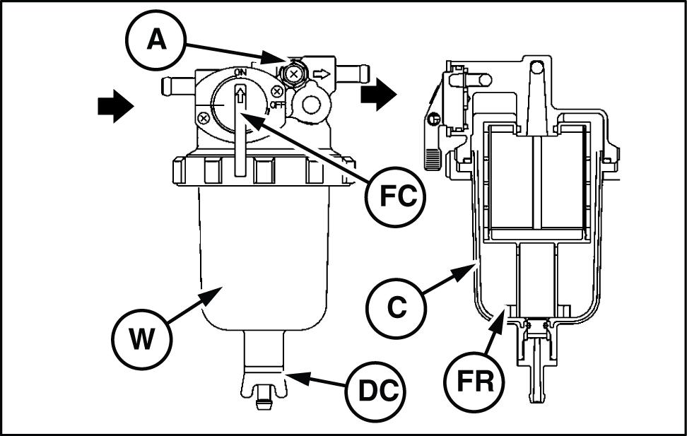
Loosen the drain cock (DC) the bottom the water separator , and drain f any water collected
T ighten the drain cock (DC) manually
Air bleeding from fuel
NOTE: drain drips when the drain cock loosen the air bleeding bolt (A) the top the water arator turning counterclockwise 2 - 3 times using driver . (This may occur case the water separator sition higher than the fuel oil level the fuel After sure tighten the air bleeding bolt (A)
Inspection after initial h operation
sure check the following points after initial h thereafter every 250 h 3 months
Lube oil and filter replacement V - belt tension check
Lubricating oil change and filter replacement s t time)
NOTICE: When engine still careful with a splash engine oil which may cause Replace gine oil after the engine oil becomes warm. most effective drain the engine oil while the engine still
early period the engine oil gets dirty rapidly cause the initial wear internal Replace the gine oil earlier Lube oil filter should also replaced when the engine oil The procedure lube oil and lube oil filter replacement follows:
Drain engine oil
• Prepare a waste oil container collecting waste oil.
Inspection item
• Remove the oil filler cap drain easily while draining the lube oil.
• Loosen the drain plug (DP) using a wrench tomer procured) drain the lube
• Securely tighten the drain plug after draining the lube
• Drain The location depends the engine installed the machine
NOTE: Use a socket wrench a closed wrench when moving tightening a drain plug. not use a spanner because there the possibility that the spanner slips and you get

Replacing
oil filter
• T urn the lube oil filter (E) counterclockwise using a filter wrench (customer procured) remove
• Clean the mounting face the oil filter .
• Moisten the new oil filter gasket with the engine oil and install the new engine oil filter manually turning clockwise until comes into contact with the ing and tighten further 3 / 4 a turn with the filter wrench.
T ightening torque: - N·m ( - )
Oil filling and inspection
• Fill with new engine oil until reaches the specified
NOTICE: not overfill the oil pan (O) with engine sure keep the specified level between upper and lower limit the dipstick (D)
T T ighten
Loosen
• W arm the engine running for 5 min while checking any oil
• Stop the engine after warming and leave ping for about min recheck the engine oil level with dipstick and replenish the engine oil. any oil wipe away with a clean
V - belt tension check
When there not enough tension the V - belt (V) , the V - belt will slip making impossible for the alternator (A) generate power and cooling water pump and cooling fan (R) will not work causing the engine
Check and adjust the V - belt tension (deflection) the lowing manner:
NOTE: especially careful not splash engine oil the V - because will cause stretching and aging the

TULI12EXN4791BB 5

Press the V - belt with your thumb [approximately N ( ) ] the middle the V - belt span check the tension
A vailable positions check and adjust the V - belt tension (deflection) are the B C direction shown the 6
Y may choose a position whichever you can ily carry out the check and adjustment the chine
• V - refers a V - belt which has been used less than 5 min a running engine.
• V - refers a V - belt which has been used a running engine for 5 min The specified deflection measured each position should follows:
TULI12EXN4792AB 6
Direction
necessary , adjust the V - belt tension
T o adjust the V - belt loosen the setscrew (S) and move the alternator (A) tighten the Vbelt.
(Adjust the V - belt tension inserting a bar
After replacing with a new V - belt and adjusting run the engine for 5 min and readjust the deflection the value the table
After replacing with a new V - belt and adjusting it, run the engine for 5 min and readjust the deflection the value the table
V isually check the V - belt for oiliness wear any , replace the V - belt with new


