SECTION 10 - ENGINE
SECTION 21 -
SECTION 25 - FRONT AXLE
SECTION 27 - REAR AXLE
SECTION 35 - HYDRAULIC SYSTEM
SECTION 39 - CHASSIS
SECTION
- STEERING
SECTION
- CAB HEATING AND
SECTION 55 - ELECTRIC SYSTEM
ELECTRIC DIAGRAMS....................................................................................................................................3
ELECTRIC DIAGRAMS - POWERSHUTTLE ROPS (580T mechanical engine)........................................3
ELECTRIC DIAGRAMS - POWERSHUTTLE CAB (580T - 580T SLA mechanical engine)......................18
ELECTRIC DIAGRAMS - POWERSHUTTLE CAB (580ST - 590ST electronic engine)............................36
ELECTRIC DIAGRAMS - POWERSHIFT CAB (580ST - 590ST electronic engine) - 2WS......................53
ELECTRIC DIAGRAMS - POWERSHIFT CAB (695ST) - 4WS.................................................................72
CONTROLS AND INSTRUMENTS.................................................................................................................91
FRONT CONTROL PANELS (580T - 580ST - 590ST)..............................................................................91
FRONT CONTROL PANELS (695ST).......................................................................................................93
CONTROL PANEL AND SIDE INSTRUMENT CLUSTER (580T mechanical engine)..............................95
CONTROL PANEL AND SIDE INSTRUMENT CLUSTER (580ST - 590ST - 695ST electronic engine)..........97
SIDE INSTRUMENT CLUSTER (580T)
SIDE INSTRUMENT CLUSTER (580ST - 590ST - 695ST).....................................................................101
SECTION 82 - LOADER ATTACHMENT
SECTION 84 - BACKHOE ATTACHMENT
SECTION 00 - SAFETY RULES
SAFETY INSTRUCTIONS
S WARNING S
This warning symbol points out important messages involving your safety.
Carefully read the safety rules contained herein and follow advised precautions to avoid potential hazards and to safeguard your safety and personal integrity.
In this manual you will find this symbol together with the following keywords:
S WARNING S
This symbol warns about the possibility of potential damages to the machine that can involve the operator’s safety.
S WARNING S
With specific warnings about potential dangers for the operator’s or other persons integrity directly or indirectly involved.
The non-compliance with the warnings preceded by the above-mentioned keywords (WARNING and DANGER) can cause serious accidents or even the death of the persons involved.
Moreover, in the present Manual, some instructions are given with text in italics, preceded by the words NOTE and CAUTION.
NOTE: it emphasizes and underlines to the operator the correct technique or correct procedure to follow.
S WARNING S
This symbol warns about the possibility of potential damages to the machine that can involve the operator’s safety.
FOREWORD
Backhoe loaders 580T - 580ST - 590ST - 695ST have been designed to perform most earth-moving operations.
If you use this machine for duties involving the use of attachments, accessories, or special tools, consult your Dealer to make sure that the adaptations or modifications carried out are in conformity with the machine’s technical specifications and with current regulations on safety.
Any modifications or adaptations which are not approved by the manufacturer may invalidate the machine’s original conformity with safety requirements.
The machine must be used according to its intended use, respecting the safety and precautionary rules and strictly following the operating instructions.
Any functional disorders, especially those affecting the safety of the machine, should therefore be rectified immediately.
S DANGER S
A different use of the excavator or of its working equipment:
-for lifting or transporting persons;
-as a working platform;
-for lifting loads without the attachment being approved for this purpose;
-for pulling loads;
-is considered unintended use.
Unintended use may cause injury or life-threatening risks for the operator and for other persons.
The manufacturer/supplier cannot be held responsible for any damage resulting from unintended use. The risk involved in such misuse lies entirely with the user.
S DANGER S
It is absolutely forbidden to tamper with and/or change the setting of any of the hydraulic system valves to avoid damaging machine components, with a consequent risk for personal safety.
The current Operator’s Manual is the user’s guide for correct run-in, use and maintenance of the machine.
Carefully read this Operator’s Manual and store it in the cab for quick location and reference.
Instructions concerning safety, operation and maintenance have been developed to permit safe service and repair of this machine without any risk.
In the event of queries or suggestions relevant to your machine do not hesitate to address to your Dealer.
Dealers have qualified and trained personnel at disposal as well as Original Spares, means and equipment suitable to carry out all necessary maintenance.
Any modifications or adaptations which are not approved by the manufacturer may invalidate the machine’s original conformity with safety requirements.
IMPORTANT: the engine and fuel system on your machine are designed and built to government emissions standards. Tampering by dealers, customers, operators and users is strictly prohibited by law. Failure to comply with this prohibition could result in government fines, rework charges, invalid warranty, legal action and possible confiscation of the machine until rework to original condition is completed. Engine service and/or repairs must be carried out by a certified technician only.
NOTE: each machine is supplied complete with a copy of this Manual. Descriptions and illustrations provided herein are not binding. The Manufacturer, provided that the basic characteristics of machine types described and shown in this Manual remain the same, reserves the right to change components, parts and accessories supplied without any commitment to timely update this publication; and this any time it deems it convenient for improvement purposes or due to commercial or manufacturing requirements. For exact information, please consult your Dealer or contact the Manufacturer’s Branch Offices, who remain at your disposal for further help.
SPARE PARTS
The “non-genuine” spare parts have not been checked and authorized by the Manufacturer.
The assembly and/or use of such products may have negative effects on the machine design features and could impair its operation safety.
The Manufacturer is not liable for any damage caused by “non-genuine” spare parts or accessories.
WARRANTY
This machine is under warranty according to the regulations in force in Your Country and in compliance with the sales agreement drawn up with the Dealer.
The warranty, however, expires if the operation and maintenance instruction for this machine and contained in this manual, have not been followed.
580ST 590ST 695ST

ENGINE INSTALLATION

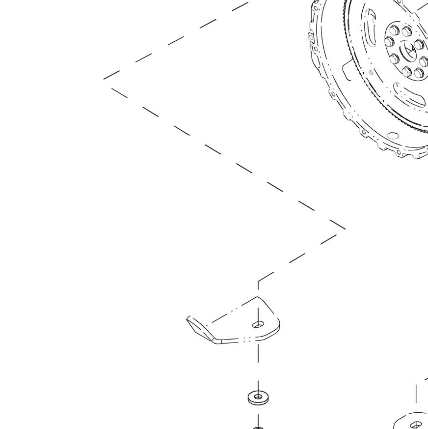


1.Front RH engine mount bracket
2.Front LH engine mount bracket
3.Washer
4.M12x35 hex screw
5.Anti-vibration device

6.Washer
7.M16x120 hex screw
8.Washer
9.M16 nut [tightening torque 210 ÷ 240 Nm (156 ÷ 178 lbf·ft)]
NOTE: Refer to SECTION 21 - TRANSMISSION for the rear RH and LH engine mount brackets.
TECHNICAL SPECIFICATIONS
DIESEL ENGINE
72 kW - 97 HP ENGINE (580T)
Specifications (ISO 14396).....................................................................................72 kW - 97 HP @ 2200 rpm
Model.......................................................................................................................................F4GE9484C*605
Type.......................................................................................................................................diesel, mechanical
No. of cylinders.................................................................................................................................................4
Valves per cylinder............................................................................................................................................2 Bore...............................................................................................................................................104
Stroke.........................................................................................................................................132
Displacement...................................................................................................................
Compression ratio.....................................................................................................................................17.5:1
Maximum torque (EC)......................................................................................420 Nm (309 lbf·ft) @ 1250 rpm
Low idle speed at no load............................................................................................................1000 ± 50 rpm
High idle speed at no load (engine not installed).........................................................................2430 ± 50 rpm
High idle speed at no load (engine not installed on the vehicle)..................................................2380 ± 60 rpm
Maximum speed at full load.................................................................................................................2200 rpm
Air intake....................................................................................................TAA (turbocharged with aftercooler)
Supply
Injection pump.............................................................................................BOSCH ROTARY VE 4/12 F1100L
Injection sequence...................................................................................................................................1-3-4-2 Cold-start device.............................................................................................................. “grid heater” (optional) Cooling
72 kW - 97 HP ENGINE (580ST)
82 kW - 110 HP ENGINE (590ST - 695ST)
Specifications (ISO 14396)...................................................................................82 kW - 110 HP @ 2200 rpm
Model (590ST).......................................................................................................................F4HE9484C*J107
Model (695ST).......................................................................................................................F4HE9484C*J108
High
High
POWERSHUTTLE TRANSMISSION
This transmission is used on powershuttle backhoe loader models 580T - 580ST - 590ST.
TECHNICAL SPECIFICATIONS
2WD/2WS TRANSMISSION - POWERSHUTTLE (580T)
4WD/2WS TRANSMISSION - POWERSHUTTLE (580ST - 590ST) Model.....................................................................................................................CARRARO
Ref.DimensionUseNotes - Miscellaneous
1 7/8” - 14 UNFOil inlet from cooler
2 7/8” - 14 UNFOil outlet to cooler
3 1/2” - 14 UNFTransmission temperature switch
4 Oil drain plug
5 1/8” - 28 BSP ISO 228Oil cooler return
6 1/8” - 28 BSP ISO 228Forward gear pressure check port
7 1/8” - 28 BSP ISO 228Reverse gear pressure check port
8 1/8” - 28 BSP ISO 228 Forward / reverse gear clutch pressure check port
0.5 ÷ 3.5 bar (7.3 ÷ 50 psi) ON forward / reverse travel position
0.5 ÷ 3.5 bar (7.3 ÷ 50 psi) ON neutral position
11 ÷ 13 bar (159 ÷ 188 psi)
0.3 bar (4.3 psi) = maximum pressure in neutral position
11 ÷ 13 bar (159 ÷ 188 psi)
0.3 bar (4.3 psi) (4.3 psi) = maximum pressure in neutral position
11 ÷ 13 bar (159 ÷ 188 psi)
0.3 bar (4.3 psi) = maximum pressure in neutral position
9 1/8” - 28 BSP ISO 228Converter pressure check port0.5 ÷ 0.9 bar (7.3 ÷ 13 psi)
10 9/16” - 18 UNFOil inlet / outlet for differential lock
11 9/16” - 18 UNFBrake oil outlet / inlet
12 9/16” - 18 UNFOil inlet from the brake
13 bar (188 psi) at 900 rpm
14.5 bar (210 psi) at 2200 rpm
13 9/16” - 18 UNF Oil inlet from service pump to brake release Brake pressure switch = 10 ± 1 bar (145 ± 14 psi)
Ref.DimensionUseNotes - Miscellaneous
1 7/8” - 14 UNFOil inlet from cooler
2 7/8” - 14 UNFOil outlet to cooler
3 1/2” - 14 UNFTransmission temperature switch
4 Oil drain plug
5 1/8” - 28 BSP ISO 228Oil cooler return
6 1/8” - 28 BSP ISO 228Forward gear pressure check port
7 1/8” - 28 BSP ISO 228Reverse gear pressure check port
8 1/8” - 28 BSP ISO 228 Forward / reverse gear pressure check port
0.5 ÷ 3.5 bar (7.3 ÷ 50 psi) ON forward / reverse travel position
0.5 ÷ 3.5 bar (7.3 ÷ 50 psi) ON neutral position
11 ÷ 13 bar (159 ÷ 188 psi)
0.3 bar (4.3 psi) = maximum pressure in neutral position
11 ÷ 13 bar (159 ÷ 188 psi)
0.3 bar (4.3 psi) = maximum pressure in neutral position
11 ÷ 13 bar (159 ÷ 188 psi)
0.3 bar (4.3 psi) = maximum pressure in neutral position
9 1/8” - 28 BSP ISO 228Converter pressure check port0.5 ÷ 0.9 bar (7.3 ÷ 13 psi)
10 9/16” - 18 UNFOil inlet / outlet for differential lock
11 9/16” - 18 UNFBrake oil outlet / inlet
12 9/16” - 18 UNFOil inlet from the brake
13 9/16” - 18 UNF Oil inlet from service pump to brake release
14 4WD pressure check port
13 bar (188 psi) at 900 rpm
14.5 bar (210 psi) at 2200 rpm
Brake pressure switch = 10 ± 1 bar (145 ± 14 psi)
13 ÷ 14 bar (188 + 203 psi) at 900 rpm
13 ÷ 15.5 bar (188 + 225 psi) at 2200 rpm
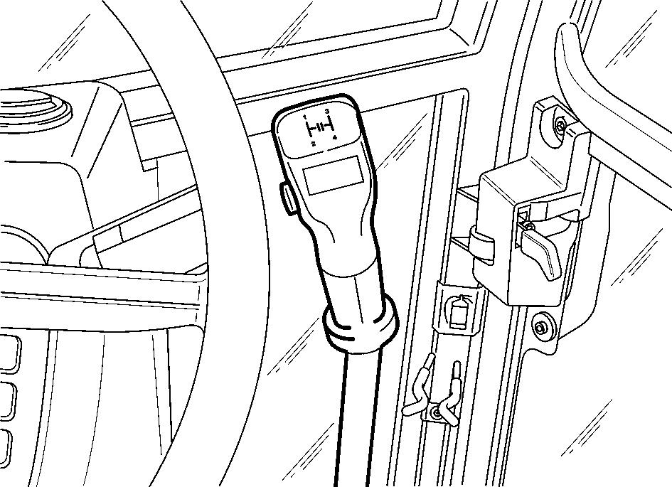
CONTROLS
1.GEARSHIFT LEVER: it is possible to select four forward and four rearward travel gears.
2.TRANSMISSION DISCONNECT BUTTON (on gearshift lever): prior to gearshifting, press and hold this switch; select the desired gear with the gearshift lever and release the switch to reengage transmission.
3.REVERSE TRAVEL LEVER: the movement of this lever from the neutral position will engage the forward or reverse travel.
4.the warning horn activates in reverse travel.
5.HORN BUTTON
6.TRANSMISSION DISCONNECT BUTTON (on loader attachment control lever).

NOTE: If there is no response to click on the link above, please download the PDF document first and then clickonit.
The transmission provides 4 forward and 4 reverse speeds. A torque converter is used to couple the engine with the transmission.
The reverse travel lever (3) allows shifting between forward and reverse travel without disengaging the gear ratios.
A device for “transmission disconnection” is activated by pushing button (2), placed on the gearshift lever (1) or by pushing button (5), placed on the loader attachment (3) control lever.
S WARNING S
Always apply the parking brake whenever the machine is parked as the machine is free to roll even though the transmission gearshift lever and power reversing lever may be “In Gear” and the engine is turned OFF.
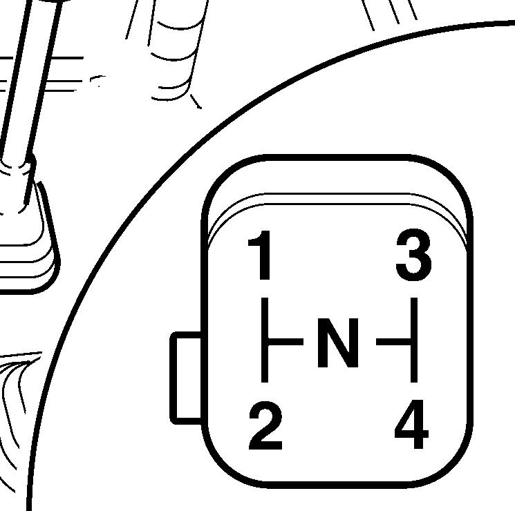
GEARSHIFT LEVER
The gearshift lever (1) is used to select any of the 4 gear ratios.
The transmission disconnect button (2) is depressed and held as the lever is shifted from one gear to another. The button is then released to reestablish the power of transmission drive.
FORWARD/REVERSE POWERSHUTTLE LEVER (TRAVEL
DIRECTION CHANGE)
To select the forward travel, engage the required gear ratio with the gearshift lever.
With the engine idling, lift the powershuttle lever from the neutral lock position (1) and move it to the forward position (2).
Use the accelerator pedal to control the engine rpm and the ground speed.
To reverse the direction of travel, reduce engine speed and move the power reversing from neutral lock position (1) and rearwards (3) for reverse travel (audible alarm device sounds).
IMPORTANT: the powershuttle lever is equipped with a neutral lock to prevent an accidental engagement of the transmission. With this design, the powershuttle lever moves through a “T” slot to the forward or reverse positions.

IMPORTANT: when operating at low environmental temperatures with cold transmission oil, allow the oil to warm up before attempting to shift the powershuttle lever. The transmission can be shifted normally after the oil warms up.
IMPORTANT: the horn will sound if the powershuttle lever is operated with the parking brake engaged.
IMPORTANT: The powershuttle lever can be activated with any engine speed. As a safety and precautionary measure, the engine must run at approximately 1200 rpm. This action is easily controlled by means of the foot accelerator to control engine and ground speed.
TRANSMISSION DISCONNECTION
The 4x4 transmission provides for easy upward and downward gear ratio changes on the move.
However, as a clutch is not used between the engine and transmission, the power flow from the engine to the transmission must be interrupted to shift from one gear ratio to another. This is accomplished by means of a transmission disconnect (dump) button.
The finger operated button (2) on the main gearshift lever knob (1) is easy to operate.
S WARNING S
Do not use the disconnect switch control down hill, because excessive speed may cause loss of control, personal injury or the failure of transmission.
To make upward gear ratio changes, simply depress and hold button (2) on the gearshift lever (1), while shifting the same from one gear ratio to another.
When the desired gear ratio has been selected release the button and allow the unit to gain engine speed and ground speed. If another higher ratio is required repeat the procedure.
IMPORTANT: to prevent possible damages to the transmission hydraulic clutches, never use the disconnect switch for inching the machine forward, because this will cause the clutches to slip excessively and to overheat.
To make downward gear ratio changes or reduce ground speed, simply lower the engine speed, depress and hold the gearshift lever button and downshift the transmission.
When the desired gear ratio has been selected release the button and adjust the engine speed to suit ground speed required.
Operating the machine in a too high gear or under a too heavy load will cause the torque converter to slip excessively and overheat. If the machine is overloaded, the engine speed will not exceed a range of 1800-2200rpm at maximum accelerator and the torque converter will “stall” bringing the machine to a complete stop.
If “stall” does occur, there is still sufficient engine power to operate the loader attachment; however, to prevent the transmission from overheating, either reduce the load on the machine or select a lower gear ratio.
IMPORTANT: operating at a “stall” for more than 20 seconds can cause the transmission to overheat and can possibly damage the transmission. If the transmission overheats, the needle (3) reaches the red field. Shift both the powershuttle lever and the gearshift lever to neutral. Let the engine run idle (1000 rpm) until transmission oil cools down enough to have the needle (3) return to correct position.
LUBRICATION
1.Oil filler tube interface
2.Oil drain plug
3.Breather