
Case 580k Phase 3 Backhoe Loader Service Repair Manual


Case 580k Phase 3 Backhoe Loader Service Repair Manual
Torque Specifications - Decimal
Torque Specificatlons - Steel Hydraulic Hardware......................................................1001-2 Fittings. .....................................................1001-4
Torque Specifications - Metric Hardware...1001-3
Torque Specifications - O-ring Face Seal Fittings. 1001-5
Use the torques in this chart when special torques are not given. These torques apply to fasteners with both UNC and UNF threads as received from suppliers, dry, or when lubricated with engine oil. Not applicable if special graphites, molydisulfide greases, or other extreme pressure lubricants are used.

1/4 in 9-11 12-15
5/16 in 17-21 23-28
3/8 in 35-42 48-57
7/16 in 54-64 73-87
1/2 in 80-96 109-130
9/16 in 110-132 149-179
5/8 in 150-180 203-244
3/4 in 270-324 366-439
7/8 in 400-480 542-651
1.0 in 580-696 787-944
1-1/8 in 800-880 1085-1193
1-1/4 in 1120-1240 1519-1681
1-3/8 in 1460-1680 1980-2278
1-1/2 in 1940-2200 2631-2983

1/4 in 12-15 16-20 5/16 in 24-29 33-39 3/8 in 45-54 61-73 7/16 in 70-84 95-114 1/2 in 110-132 149-179 9/16 in 160-192 217-260 5/8 in 220-264 298-358 3/4 in 380-456 515-618 7/8 in 600-720 814-976
1.0 in 900-1080 1220-1465
1-1/8 in 1280-1440 1736-1953
1-1/4 in 1820-2000 2468-2712
1-3/8 in 2380-2720 3227-3688 1-1/2 in 3160-3560 4285-4827
NOTE: Use thick nuts with Grade 8 do/ts.
811360B
Use the following toques when special torques are not given.
These values apply to fasteners with coarse threads as received from supplier, plated or unplated, or when lubricated with engine oil. These values do not apply if graphite or molydisulfide grease or oil if used.


M16
M30 920-1100 1250-1500 M36 1600-1950 2175-2600

Usually the torque values specified for grade 10.9 fasteners can be used satisfactorily on grade 12.9 fasteners.
37 Degree Flare Fittings
1/4 in 7/16-20 6-12 8-16 6.4 mm
5/16 in 1/2-20 8-16 11-21 7.9 mm
3/8 in 9/16-18 10-25 14-33 9.5 mm
1/2 in 3/4-16 15-42 20-56 12.7 mm
5/8 in 7/8-14 25-58 34-78 15.9 mm
3/4 in 1-1/16-12 40-80 54-108 19.0 mm
7/Bin 1-3/16-12 60-100 81-135 22.2 mm
1.0 in 1-5/16-12 75-.117 102-158 25.4 mm
1-1/4 in 1-5/8-12 125-165 169-223 31.8 mm
1-1/2 in 1-7/8-12 210-250 285-338 38.1 mm
Size PoundFeet Newton metres
5/16-18 15-20 20-27
3/8-16 20-25 26-33
7/16-14 35-45 47-61
1/2-13 55-65 74-88
5/8-11 140-150 190-203
Straight Threads with O-ring
1/4 in 7/16-20 12-19 16-25 6.4 mm
5/16 in 1/2-20 16-25 22-23 7.9 mm
3/8 in 9/16-18 25-40 34-54 9.5 mm 1/2 in 3/4-16 42-67 57-90 12.7 mm
in 7/8-14 58-92 79-124 15.9 mm 3/4 in 1-1/16-12 80-128 108-174 19.0 mm 7/8 in 1-3/16-12 100-160 136-216 22.2 mm 1.0 in 1-5/16-12 117-187 159-253 25.4 mm 1-1/4 in 1-5/8-12 165-264
in 1-7/8-12

Engine
Engine Cooling System
Hydraulic System
Transmission
Front Axle - Four Wheel Drive
Brake Reservoir Type
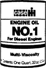
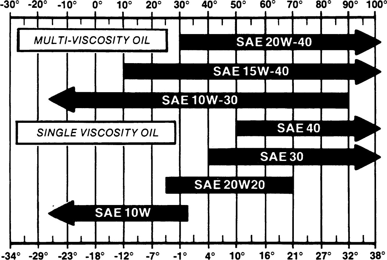
CaselH No. 1 Multi-Viscosity Engine Oil is recommended for use in your Case engine. The ambient temperature range for multi-viscosity oil is much larger than the ambient temperature range for singleviscosity oil. See the Engine Oil Viscosity Chart below.
Single viscosity lubricants can be used in this engine if the ambient temperature range between oil changes remains within the limits for that oil.
Only use lubricants with API classification of CC/CD, CD/SF, CD, or CE.


NOTE: Do not put “Performance Additives" or other oil additive prodUCts ln the engine crankcase. The oil change interval given in this manual is according to tests With Case lubricants.
Use No. 2 diesel fuel in the engine of Fuel Storage this machine. The use of other fuels can cause theloss of engine power and high fuel consumption.
In very cold temperatures, a mixture of No.1 and No. 2 diesel fuels is temporarily permitted. See the following Note.
NOTE: See your fuel dea/er for winter fuel requirements in your area. If the temperature of the fuel is below the cloud point(wax appearance point), wax crystals in the fuel will caUse the engine to lose power or not start.
The diesel fuel used in this machine must meet the specifications in the chart below or Specification D975-81 of the American Society for Testing and Materials.
If you keep fuel in storage for a period of time, you can get foreign material or water in the fuel storage tank. Many engine problems are caused by water in the fuel.
Keep the fuel storage tank outside and keep the fuel as cool as possible. Remove water from the storage container at regular periods of time.
for Acceptable No. 2 Diesel
API gravity, minimum .....................................................................................
Flash point, minimum 140°F (60°C)
Cloud point (wax appearance point), maximum
-5°F (-20°C) See Note above Pour point, maximum. -15°F (-26°C) See Note above
Distillation temperature, 90% point 540 to 640°F (282 to 338°C)
Viscosity, at 100°F (88°C)
Centistokes 2.0 to 4.3
Saybolt Seconds Universal 32 to 40
Cetane number, minimum 43 (45 to 55 for winter or high altitudes)
Water and sediment, by volume, maximum. 0.05 of 1%
Sulfur, by weight, maximum. 0.5 of 1%
Copper strips corrosion, maximum ..No. 2
Ash, by weight, maximum................,. 0.01 of 1%
Written In C/ear And Simple English
IMPORTANT: This engine was made using the metric measurement system. All measurements and checks must be made with metric tools to make sure of an accurate reading when inspecting parts.
Fill the engine crankcase with CC or CD service classification oil that has the correct viscosity rating for the ambient air temperature. Install new oil filters, after the engine has been rebuilt.
Step 1 Disconnect the wire to the electric shut-off on the injection pump so that the engine will not start. Crank the engine for 30 seconds until there is oil pressure, then reconnect the wire.
Step 2 Remove the air from the cooling system at the temperature sending unit.
Step 3 Run the engine at 1000 RPM minimum load for 5 minutes and check for oil leaks.
Step 4 During the Run-In, continue to check the oil pressure, coolant level, and coolant temperature.
The following procedure must be followed when using a PTO dynamometer to Run-In the engine. The dynamometer will control the engine load at each speed and will remove stress on new parts during Run-In.
During the Run-In, continue to check the oil pressure, coolant level and coolant temperature.
For the first 8 hours of field operation stay one gear lower than normal. For the next 12 hours DO NOT ”lug” the engine. Prevent ”lugging” by moving the lever to a lower gear. The engine must not be ”lugged” below the rated engine RPM during early hours of life.
For the first 8 hours, operate the engine at full throttle maintaining a normal load. DO NOT ”baby” the engine, but avoid converter or hydraulic stall. The engine must not be ”lugged” below the Rated Engine RPM (Do not stall the engine more than 10 seconds).
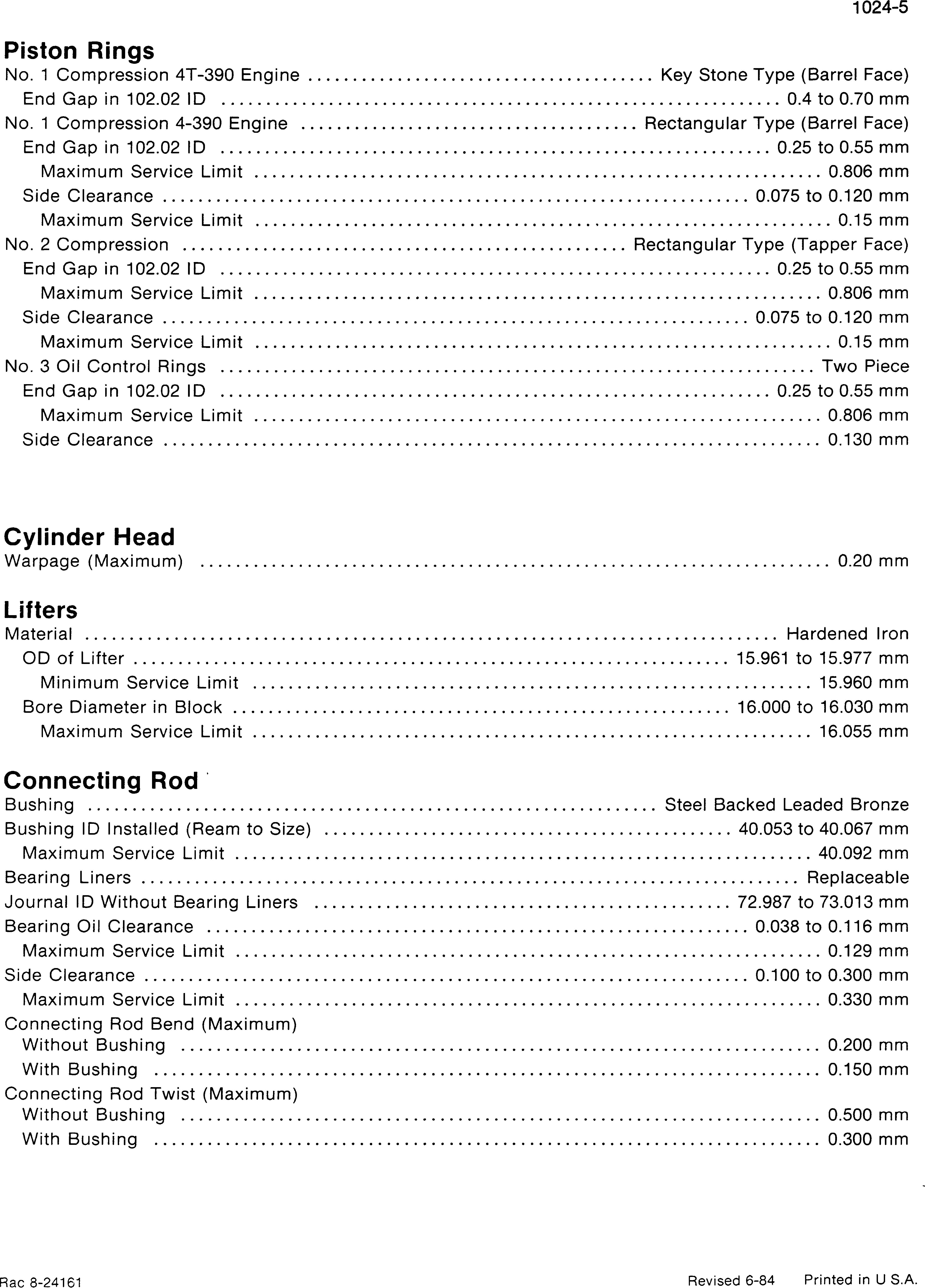
Block
Out of Round (Maximum)
Taper (Maximum)
0.5 mm Oversize Piston
Type
at 12 mm From the Bottom, 90 Degrees Piston Pin
Width of 1st Ring Groove (Top)
Width of 2nd Ring Groove (Intermediate)
to 2.485 mm
to 2.445 mm Width of 3rd Ring Groove (Oil Ring)
Protrusion Above Cylinder Block (Maximum)
mm
mm
Type FuII Float
of Pin
to 40.003 mm
Service Limit 39.990 mm
Full download: http://manualplace.com/download/case-580k-phase-3-service-manual/